Description
Solar air heater, adaptable to any type of house, by Guy Isabel.
Sommaire
Sommaire
- 1 Description
- 2 Sommaire
- 3 Introduction
- 4 Video d'introduction
- 5 Étape 1 - Téléchager les plans CAO
- 6 Étape 2 - Frame
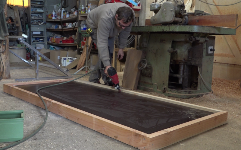
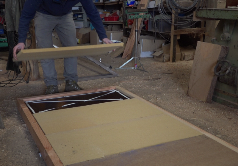
- 7 Étape 3 - Background and insulation of the frame
- 8 Étape 4 - Opening the sensor input and output
- 9 Étape 5 - Optional: Rain protection
- 10 Étape 6 - Summer hatch
- 11 Étape 7 - Reflective surface
- 12 Étape 8 - Glass weatherstrip
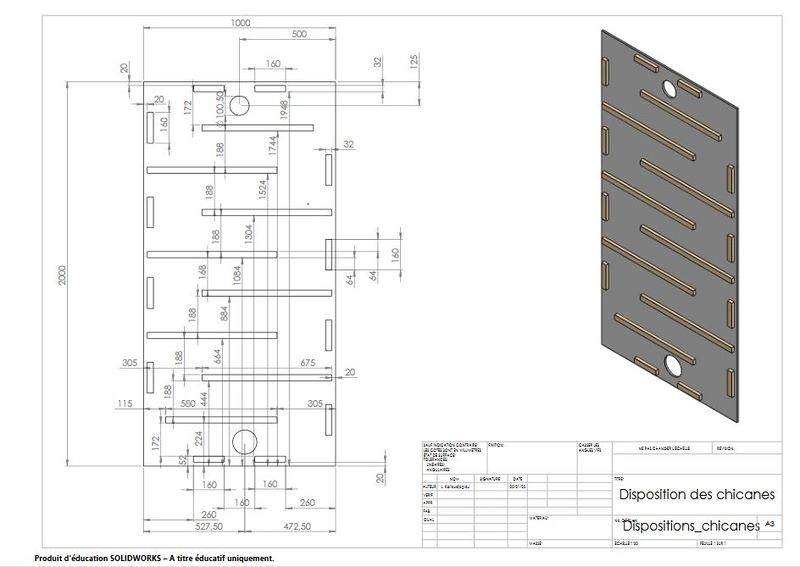
- 13 Étape 9 - Baffle circuit
- 14 Étape 10 - Slate laying
- 15 Étape 11 - Oiling and varnishing
- 16 Étape 12 - Installing the glass
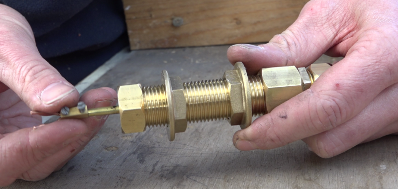
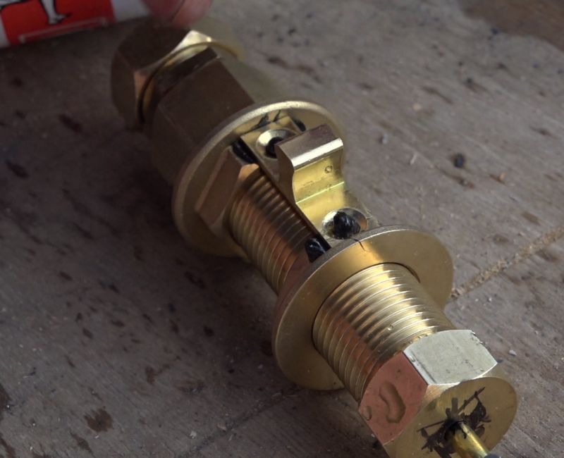
- 17 Étape 13 - Valve system, fixed part
- 18 Étape 14 - Valve system, moving part
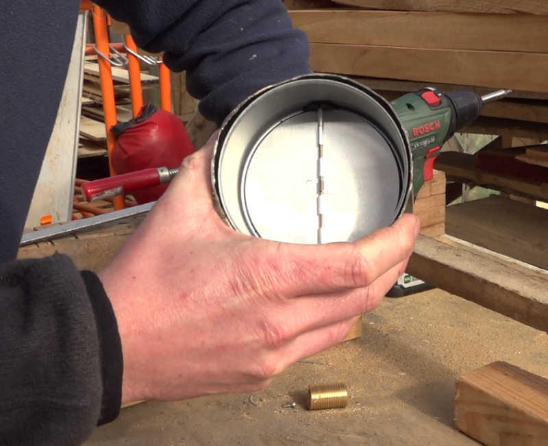
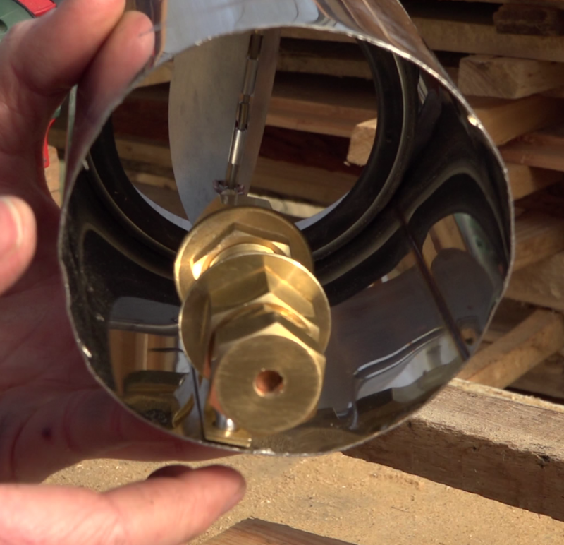
- 19 Étape 15 - Valve system, Assembly
- 20 Étape 16 - Installation
- 21 Étape 17 - use
- 22 Étape 18 -
- 23 Commentaires
Introduction
The design of this solar heating was strongly inspired by Guy Isabel, on the plans he describes in his book Les capteurs solaires à air, Eyrolles edition.
The sun transmits energy to the earth by radiation. At the equator, the radiation reaches the power of 1000 W / m², it is by comparison, the power of a small electric heater.
Solar energy is a free and intermittent energy, which is relatively simple to transform efficiently as heat, (yield easily above 60%).
This website allows to know according to the season and the geographical position, many parameters such as the maximum power per m², the angle of the sun compared to the place.
This other website makes it possible to calculate these values almost everywhere on earth by taking into account the horizon line, the orientation of the panels and other parameters. The values displayed by default correspond to the photovoltaic energy generated, but it is possible to display the radiation in kwh/m².
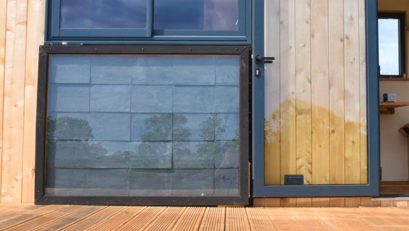
Solar air heater
Concretely, it is a question of transforming the solar radiation into heat thanks to what is called a black body (for example the very hot tar in the summer or the dashboard of a car parked in full sun).
For housing, the most common systems on this principle are solar water heaters, often installed on the slopes of roofs to make domestic hot water supplements of conventional systems.
Less known, the air sensor allows to heat the air of a room.
This tutorial presents the manufacture of an air sensor of 2 m² designed for the heating of the air of a room of 10 to 15 m² of 5 to 7 ° C winter on average, for France. It is a complement to the conventional heating system, which allows appreciable financial and ecological savings. At a cost of around € 200, it is quickly amortized.
Principle
In winter, the sensor sucks in the air from below, heats it thanks to the shaving sun, then restores it to the habitat through the high outlet, at a temperature of up to 70 ° C locally instantly diluted in the ambient atmosphere.
In summer, an external hatch allows to reject the hot air of the sensor outside while aspiring at the same time the air of the habitat, thus creating a natural ventilation.
A valve connected to a thermostatic jack, allows to manage automatically and without electricity, the opening of the air circulation, only when it has reached more than 25 ° C in the sensor.
Retrouvez dans ce rapport une analyse à l'usage de ce chauffage solaire, ainsi que des 11 autres low-techs expérimentées lors du projet En Quête d'un Habitat Durable.Youtube
Matériaux
The tutorial presented here is 2.09m x 1.09m overall
Sensor:
- Chevron Douglas (here the final section is 95mm x 45mm)
- 2 of 2m10
- 2 of 1m10
- 15 m of douglas sheets (20mm x 53mm)
- Rigid plate (here plywood filmed, 10mm)
- Rigid insulation (here Steico plate, 22mm)
- Sika cartridge
- Silicone cartridge
- PU glue for outdoor wood gluing
- Wood glue
- Nails
- Wood screws, from 30mm to 150mm
- Comprehensive seal
- Linseed oil
- Wood varnish
- 15 m of douglas sheets (30mm x 16 mm)
- Aluminum adhesive
- Tempered glass or polycarbonate plate (1m x 2m)
- Expanded metal grid (300mm x 50mm)
- 4 screw legs (example)
- 1m of aluminum drip 100mm width (example)
- Double-sided adhesive
- Thin insulation (here parquet insulation)
- 30 to 35 slates 320mm x 220mm, thickness 3,5mm
- 8 reinforced squares, mini width 40mm
- 1 tube diameter 100mm length of the housing wall, pvc / aluminum / stainless steel for the low entrance
Valve system:
- 1 Thermostatic cylinder Vernet EL 0769
- 100mm of brass tube diameter 4mm
- compression spring length 70mm
- 1 washer
- 1 small screw
- 2 rivets
- 5 cm of copper wire diameter 2mm
- 1 domino electrician diameter 4mm
- Plumbing / gas equipment:
- 100mm of threaded brass tube 15/21
- 2 brass blind nuts 15/21
- 1 brass through nut 15/21
- 1 copper sleeve diameter 12mm
- 1 copper sleeve diameter 14mm
- 1 brass nipple 15/21
- 1 ventilation valve, here diameter 100mm
- 1 ball catch
- 1 aluminum or stainless steel tube along the wall of the house wall, diameter of the valve
optional:
- Rain barrier
- Sealant
Outils
- Wood saw
- Screwdriver / drill and wood / metal drills
- Wall stapler
- Paint brushes
- Hammer
- Cutter
- Grinder and diamond / metal discs
Étape 1 - Téléchager les plans CAO
Des plans détaillés et CAO ont été réalisée par Enerlog. Ils sont disponibles en open-source ici: https://cloud.ecutsa.fr/index.php/s/apRoi395xdQb52T#pdfviewer
Ces plans ont servi à la réalisation d’une première version construite en atelier. Ces plans sont ici partagés afin de répondre à un des objectifs d’Enerlog: soutenir la réappropriation des savoirs par les citoyens en partageant la connaissance et en favorisant sa transmission.
Étape 2 - Frame
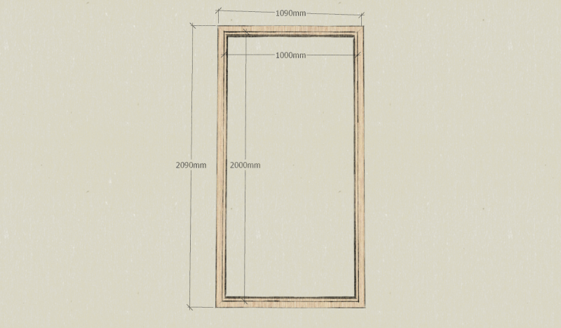
Note: Here, the frame is sized to accommodate a glass 1m x 2m by 6mm thick, a 10mm film plywood bottom and a 22mm insulating layer in STEICO. The dimensions will therefore be adapted according to the availability of each.
- Prepare 2 rafters of section 93mm x 45mm and 209 cm in length.
- Prepare 2 rafters of section 93mm x 45mm and 109 cm in length.
- Prepare 2 battens of section 20mm x 53mm and 209 cm long.
- Prepare 2 battens of section 20mm x 53mm and 109 cm long.
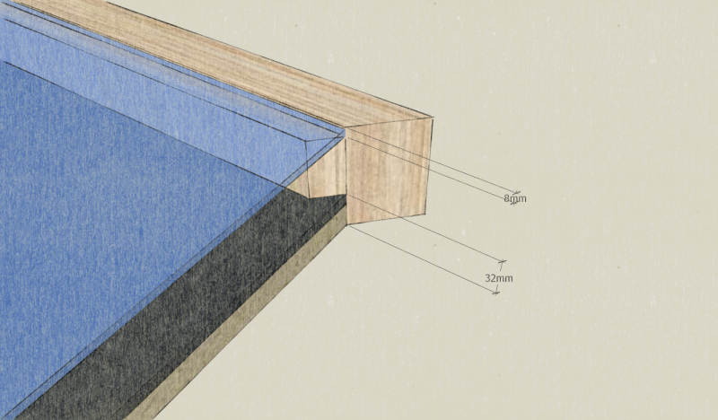
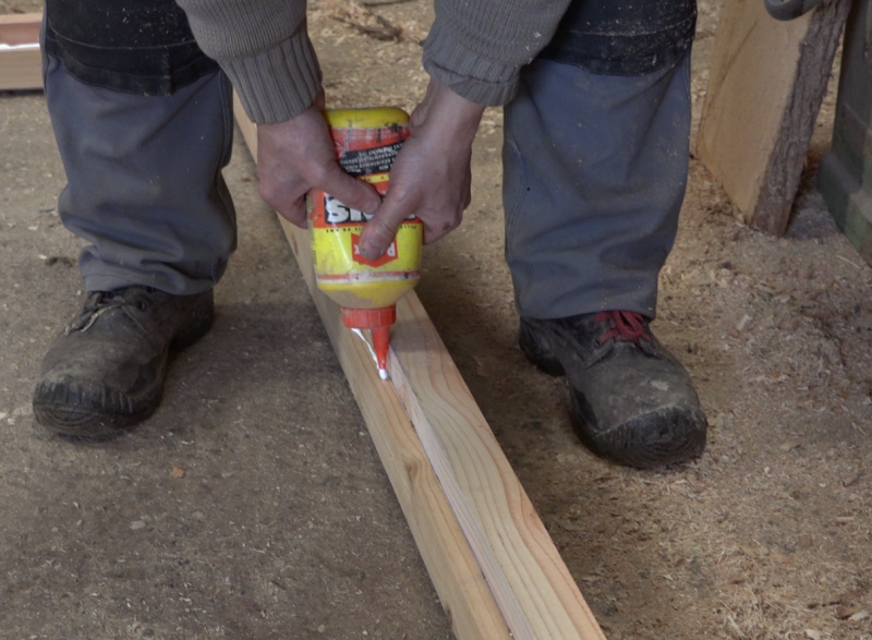
- Glue PU glue and screw the battens on the rafters associated a face of 93mm thick, 32mm from one of the edges.
Note: These 32mm correspond to the insulating thickness + filmed plywood. There is 8mm remaining on the other edge to accommodate the thickness of the glass and a seal comribande.
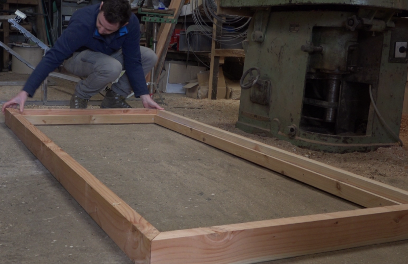
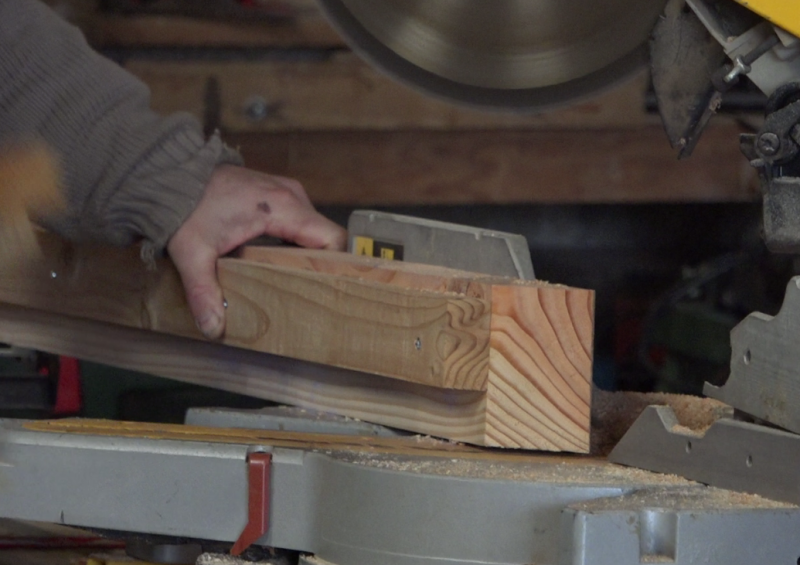
- Cut the corners of each wood profile thus obtained at 45 °, paying careful attention to the direction of the cut. The cut is made on the length of 93mm.
Note: This cut allows to find the dimension 1m x 2m of the window inside the frame.
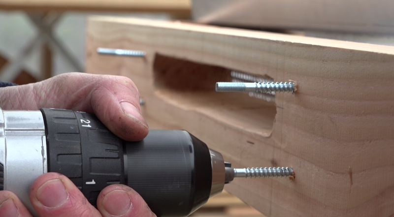
- Assemble the frame using PU glue and long wood screws in each of the 4 corners.
Étape 18 -
Published



 Français
 English
 Deutsch
 Español
 Italiano
 Português