Description
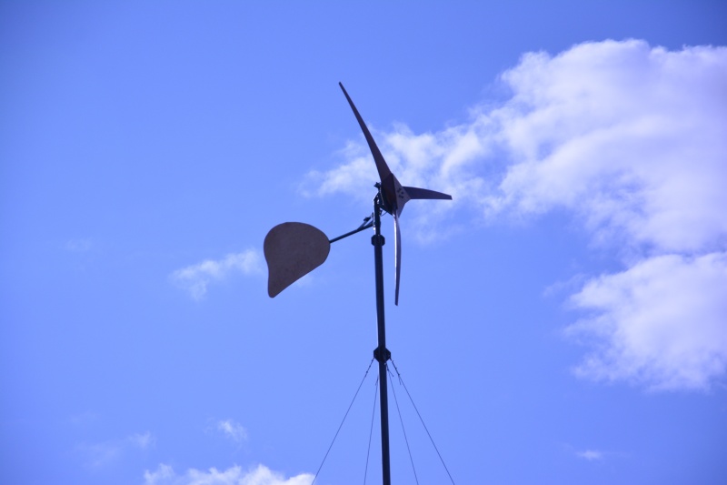
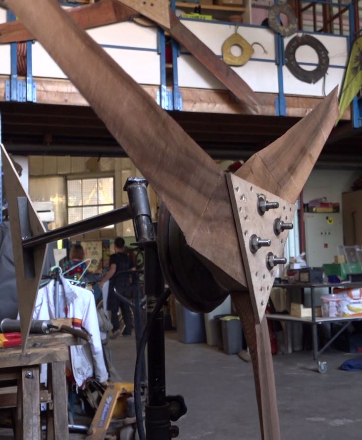
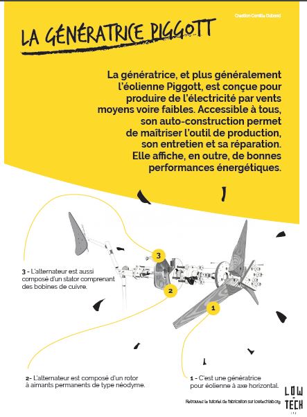
The hand-crafted 200W, 4 ft wingspan Piggott wind turbine.
Sommaire
Sommaire
- 1 Description
- 2 Sommaire
- 3 Introduction
- 4 Video d'introduction
- 5 Étape 1 - Propeller: The pattern
- 6 Étape 2 - Propeller: drawing and cutting of the blades.
- 7 Étape 3 - Propeller: Sculpture of the lower surface of the blades
- 8 Étape 4 - Propeller: Sculpture of the lower surface of the blades
- 9 Étape 5 - Propeller: Blade profile finalization
- 10 Étape 6 - Propeller: Construction of assembly supports
- 11 Étape 7 - Propeller: Assembly
- 12 Étape 8 - Generator, stator: Preparation of the cradle.
- 13 Étape 9 - Generator, stator: Preparation threaded rods stator
- 14 Étape 10 - Generator, stator: Preparation of the coil.
- 15 Étape 11 - Generator, stator: Making of 6 coils.
- 16 Étape 12 - Generator, stator: "Star" mounting
- 17 Étape 13 - Generator, stator: Three-phase cable
- 18 Étape 14 - Generator, stator: Making the stator mould
- 19 Étape 15 - Generator, stator: Preparation of the molding.
- 20 Étape 16 - Generator, stator: Molding.
- 21 Étape 17 - Génératrice, rotor: Préparation du disque métallique.
- 22 Étape 18 - Génératrice, rotor: Préparation de la cloche du moyeu
- 23 Étape 19 - Génératrice, rotor: Préparation du gabarit
- 24 Étape 20 - Génératrice, rotor: Collage des aimants
- 25 Étape 21 - Génératrice, rotor: Préparation du moule
- 26 Étape 22 - Génératrice, rotor: Préparation du moulage
- 27 Étape 23 - Génératrice, rotor: Moulage
- 28 Étape 24 - Structure, Nacelle
- 29 Étape 25 - Structure, Safran
- 30 Étape 26 - Assemblage, Génératrice
- 31 Étape 27 - Assemblage final et test de production
- 32 Étape 28 - Équilibrage des pales.
- 33 Étape 29 - Graissage de l'éolienne
- 34 Étape 30 - Installation redresseur 12V continue
- 35 Étape 31 - Contenu pédagogique à télécharger
- 36 Notes et références
- 37 Commentaires
Introduction
Retrouvez Ici la vidéo tutoriel
This tutorial is based on the work of Scotsman Hugh Piggott Hugh Piggott. It was directed with the help of Aurélie Guibert, a member of the Tripalium Network in Valence, France.
It is about building a windmill of maximum power of 200W in 12V for a wingspan of 1m 20. It is designed for low power requirements such as lighting an LED or charging of a laptop.
The distribution part of the electricity and the matting are not given in detail here.
The Wind
The power that the wind produces est proportional to the cube of its speed. For example, the windmill in this tutorial receives in its propeller 0.7W when the wind blows at 1m/s and a thousand times more at 10m/s.
To calculate it: P= 1/2 x Rho x S x v^3 with P: power (W), Rho: density of the air (about 1.23 kg/m 3), S: Surface swept by the propeller (m²), v: velocity of wind (m/s)
It is therefore necessary to study the land where we install the windmill to see if the wind blows relatively constant and with sufficient speed for producing minimum energy.
Like every other system, a part of energy is lost by the windmill. In theory, a windmill can never transform more than 60% of the energy that the wind provides, this is the Betz limit. In practice, with the type of windmill developed in this tutorial, the efficiency can reach up to 35%.
The location
Generally, it is better to have land free from trees and dwellings. The windmills of the same height placed in cities or on the gables of the houses produce much less energy because of the wind's turbulence. Similarly, the wind is more constant and powerful on an altitude, therefore it is preferred to install a small windmill at height than a big windmill at a low altitude.
Cost
Although it is a Low-tech, the cost of constructing this windmill is around 350€ if all the materials are bought. Including the matting and the electronics, the cost is around 2000€. It can be interesting to install it in off-grid areas with a view to autonomy. In the case of a network connection, it is not financially attractive.Youtube
Matériaux
List of materials required for the propeller, refer to the chapters for details
- Scraps of plywood
- Plank section minimum 95mm x 35mm, length 1m80. (red cedar or douglas or larch or spruce )
- Plywood 9mm
- Some screws of diameter 5mm, length 30mm.
List of materials required for the generator, refer to the chapters for details
- Metal disc of thickness 8mm and diameter 140mm.
- Rear wheel hub of golf, corsa, polo or Ibiza.
- 25cm of threaded rods with diameter 12mm.
- Pack of nuts of 12mm.
- 30cm threaded rods of diameter 10mm, 4 nuts of 10mm.
- Scraps of metal tube and angle.
- 4 nails of diameter 6mm.
- 1.5kg of enamelled copper wire, diameter 1.4mm.
- Electrical scotch.
- Heat-shrink tubes
- Plywood 9mm et 16mm.
- Glass fiber cloth (approximately 300g/m²)
- Polyester resin, associated catalyst
- Talc.
- Mould release wax
- 8 neodymium magnets.
- Steel disc of diameter 230mm, thickness 6mm.
- Bolts 12mm.
List of materials required for the steel structure, refer to the chapters for details
- Angle of 206mm (50x50x6mm).
- Tube of outer diameter 42.2mm, length 100mm.
- Tube of outer diameter 33.4mm, length 150mm.
- Tube of outer diameter 42.2mm, length 130mm.
- Iron plate 50 x 50 x 6mm.
- Tube of outer diameter 33.4mm, length 700mm.
- Angle 30 x 30 x 5, length 250mm.
- 60 cm of threaded rods with diameter 12mm.
Outils
List indicative of equipment, refer to the chapters for details
- Saws (hand, jigsaw, circular).
- Pencils, markers.
- Measuring tape, ruler, try-square, compass.
- Clamps
- Palm plane, wood chisels, spokeshave, hand planes.
- Drill, screwdriver, metal and wood drill up to 14mm, a Hole Cutter of diameter 60mm.
- Grinding machine, cutting blades, grinding discs, gloves and safety glasses.
- Welding station.
- Soldering iron, tin.
- electronic scale.
- graduated syringes.
- Latex gloves.
- Plastic trays,
- Pair of scissors.
- Voltmeter
Étape 1 - Propeller: The pattern
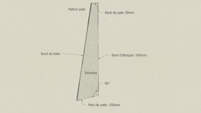
- Draw and cut the blade pattern in a board.
- Note on each side of the pattern, the one which corresponds the lower surface and the one which corresponds the upper surface.
Note : The lower surface is the side of the blade which receives the wind, the upper surface is the back side of the blade.
Étape 2 - Propeller: drawing and cutting of the blades.
- Choose a plank of dimension minimum 95mm x 35mm
Notes:
1) The wood should be imputrescible, light-weighted and easy to work with. For example, red cedar, Oregon pine, spruce, larch, douglas fir may be suitable.
2) For this tutorial, the section of the red cedar plank is 150mm x 45mm.
3) The parameter which determines the energy transmitted by the wind at the propeller is the length of the blade and not it’s breadth.
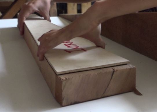
- With the help of the blade pattern, lower side visible, mark the location for the first blade.
Notes:
1) Put the knots and defects of the wood at the end of the blade, so that the thinnest part does not become fragile (middle-end of the blade).
2) Select the leading edge ridge as neatly as possible. This ridge will not be altered during the cutting of the blade.
3) Extend the blade tip pattern by 4-5 cm to maintain a margin in case of damage.
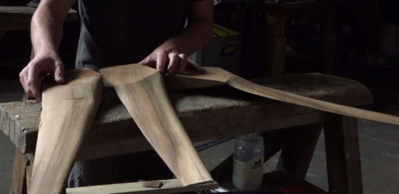
- Do the same for the 2 other blades and cut the blades.
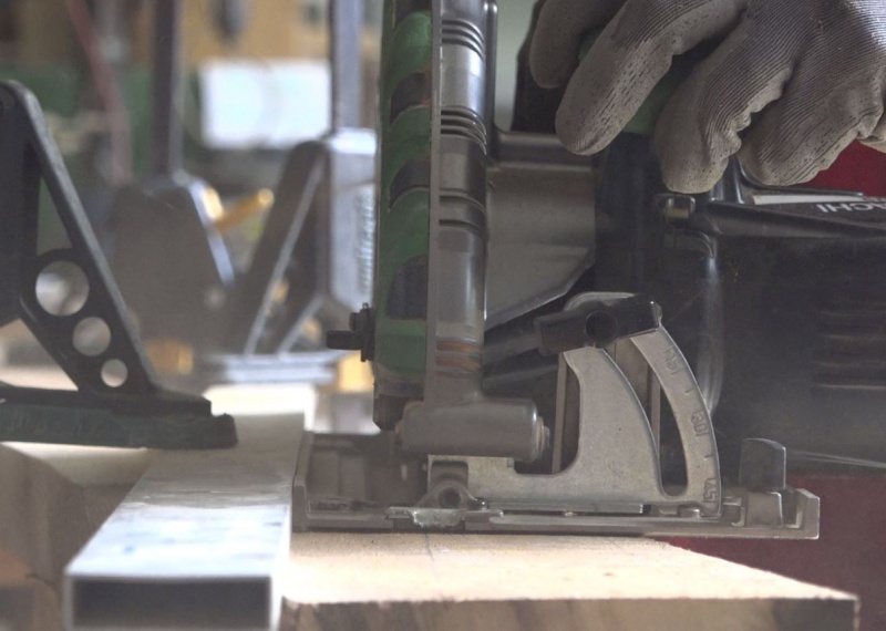
Note: When using a circular saw for cutting, be careful to place the width of the blade always on the outside of the line.
- Rectify the left of the blades if necessary with the help of a plane.
- Fix the 3 blades together with the help of the clamps and equalize all the irregular planes. All the 3 blades needs to be strictly identical.
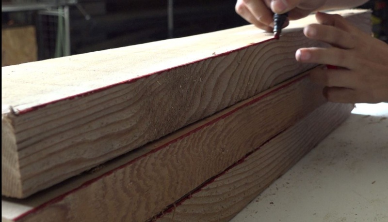
- Mark the position of the leading edge ridge for it to stay where it is. It will be its landmark.
Étape 3 - Propeller: Sculpture of the lower surface of the blades
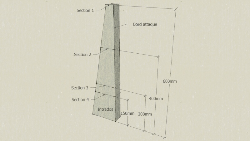
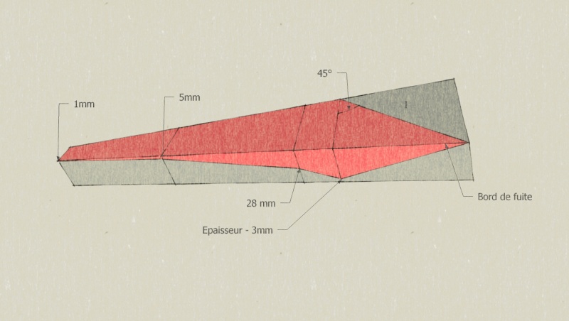
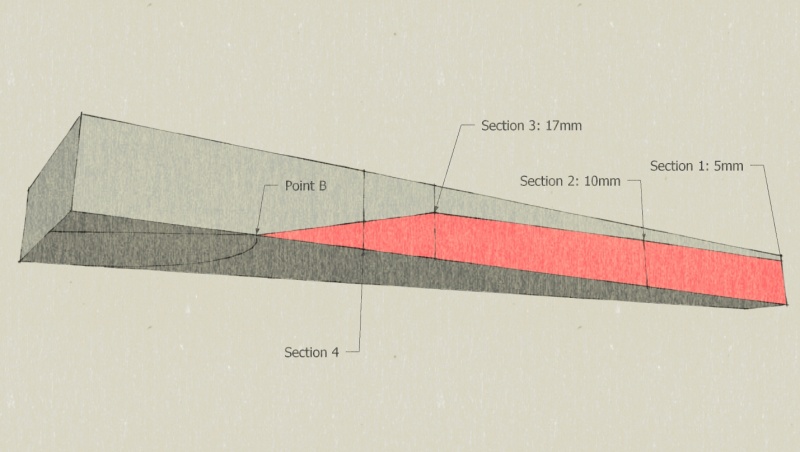
- According to the diagram, draw the 4 sections along the blade.
- According to the diagram, draw the area of the inner surface to be sculpted.
- For easy reference, hatch/shade the area of the wood to be eliminated.
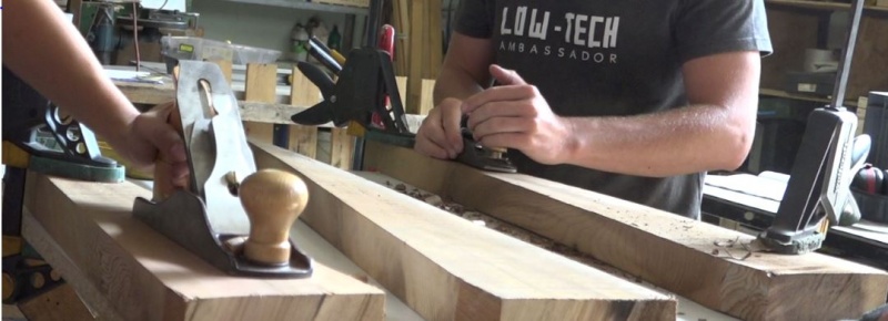
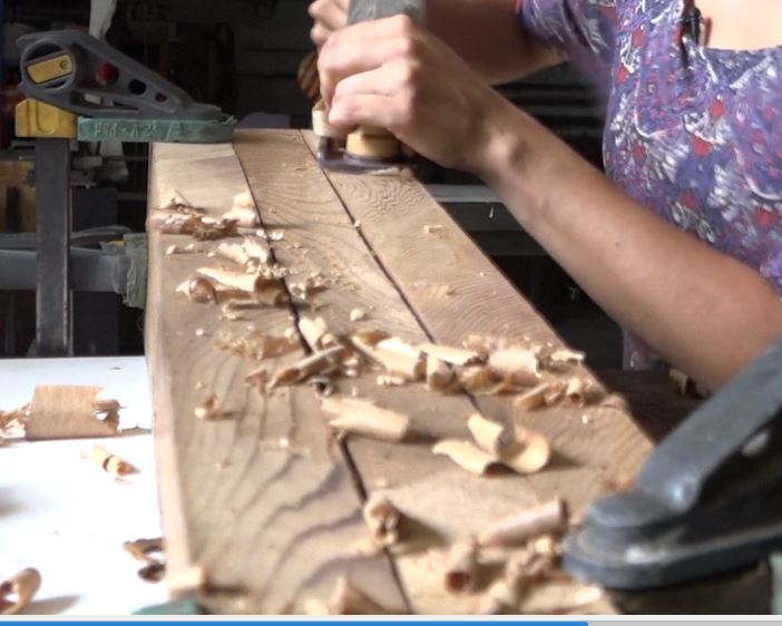
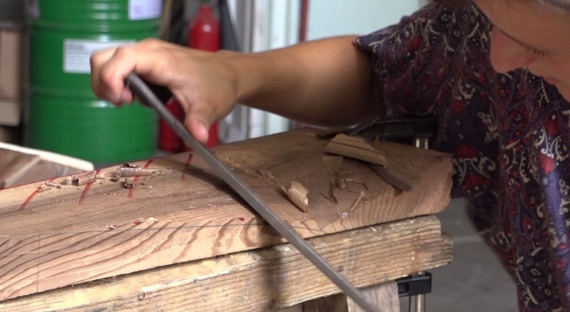
- With the help of a plane, chisels, and a spokeshave for the finishing, cut off the hatched/shaded part of the wood.
Note: To guarantee good dimensions, the sculpture must come as close as possible to the pencil stroke without erasing it.
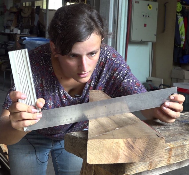
- With the help of a scale, check the evenness of all sections of the sculpted lower surface of the blade.
- Once the 3 blades are finished, check if all the dimensions are equal on multiple points on the 4 sections drawn previously.
Étape 4 - Propeller: Sculpture of the lower surface of the blades
- Position the blade in such a way that it's upper surface is visible.
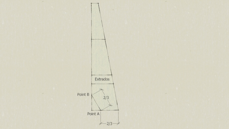
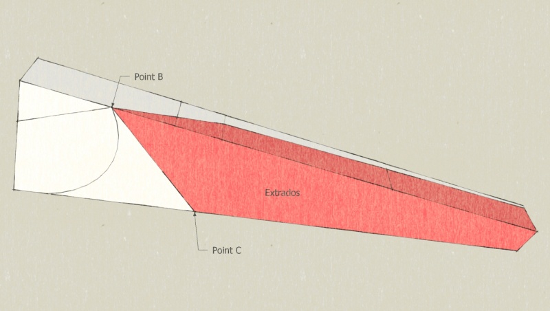
- According to the diagram, draw the point A. It is on 2/3 of the width of the blade's base from the trailing edge. This point is the center of rotation of the propeller.
- Then draw the point B on the leading edge by using a compass centered in A the 2/3 of the blade base. Then join AB.
Note: The segment AB form an angle of 120° with the base of the blade, which will be later required for the assembly of the blades.
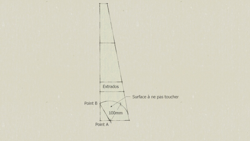
- According to the diagram, draw a circle of radius 100mm centered at A. The surface of this portion of the disc should be left intact and levelled until the end for proper blade assembly.
Note: In the case of this tutorial, the point B is situated on the perimeter of the circle. This is not always the case depending on the width of the plank.
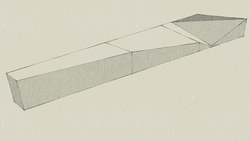
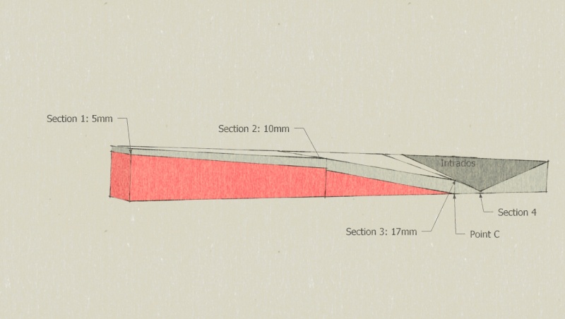
- According to the diagram, draw the thickness of the blade on the irregular planes.
Note: According to the thickness of the plank, it might appear that the thickness is not 17mm in section 3. Imagine a point in the space for the thickness 17mm on the rear edge on this section 3.
- Name C to the intersection between the point traced for the thickness and the base of the blade.
- According to the diagram, then draw the thickness of the blade at the front edge respecting the same thickness as that of the irregular plane. Connect the point of the section 3 to the point B.
- On the upper surface side, connect B and C to close the area to be sculpted.
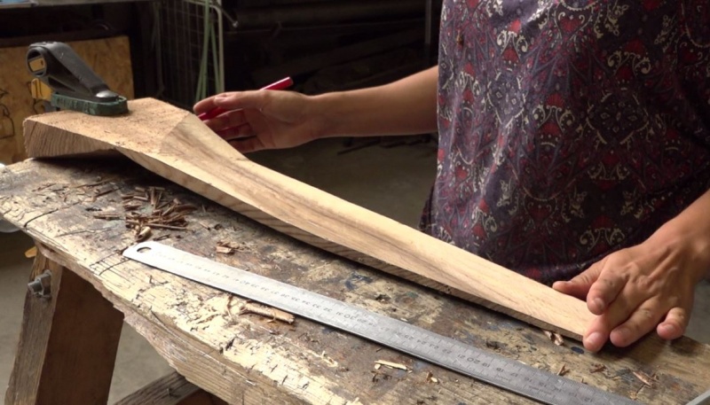
- For easy reference, hatch/shade the area of the wood to be eliminated.
- With the help of a plane, chisels, and a spokeshave for the finishing, cut off the hatched/shaded part of the wood.
Note: To guarantee good dimensions, the sculpture must come as close as possible to the pencil stroke without erasing it.
- With the help of a scale, check the evenness of all sections of the sculpted lower surface of the blade.
- Once the 3 blades are finished, check if all the dimensions are equal on multiple points on the 4 sections drawn previously.
Étape 5 - Propeller: Blade profile finalization
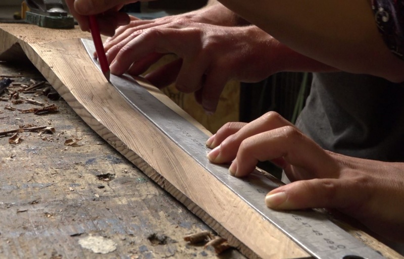
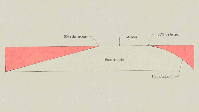
- On the upper surface, draw a line representing 30% of the width of the blade and a line representing 50% of the width of the blade from the leading edge.
- Check, with the help of the caliper compass, the thickness of each section on the line of 30%. Compare the 3 blades and adjust the thicker ones if they are not exactly identical.
Note: The 30% line corresponds to the final thickness of the blade, which is why we check the dimensions at this precise location.
- From the 50% line to the rear edge, sculpt a flat surface leaving a thickness of less than 1 mm on the rear edge.
Note: Be careful not to crack the rear edge as it is very delicate area.
- From the leading edge to the 30% line, sculpt a beautiful rounding using a hand plane, spokeshaven or palm plane. The angle of the leading edge should be approximately 60°.
- When these two areas are complete, break the remaining 50% line block to achieve a continuous profile from leading edge to trailing edge. The only line still visible in pencil should be the 30% line.
Once the work on the 3 blades is completed:
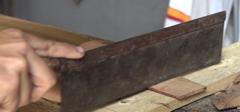
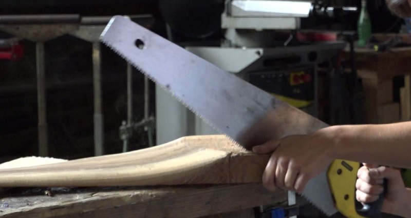
- Saw the blades at 600mm to remove the margin left at the beginning of the blade tip with a Japanese saw.
- Saw the section marked as AB on the base of the blade to the interlock the 3 blades at 120°.
Note: The angle should be slightly less than 120° in order to be able to rotate the blades slightly during assembly.
Étape 6 - Propeller: Construction of assembly supports
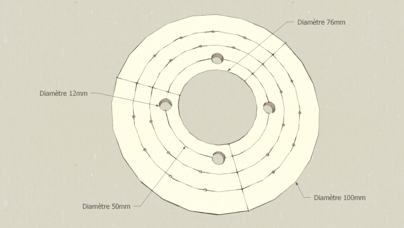
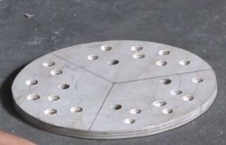
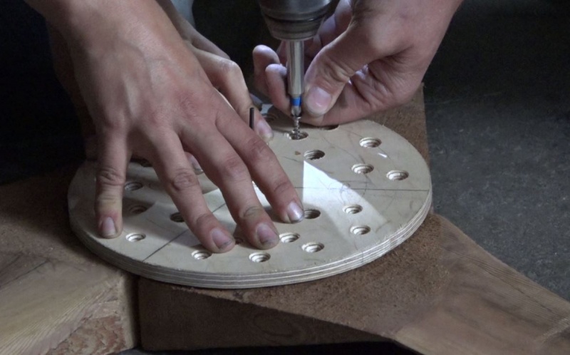
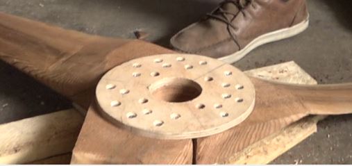
- According to the diagram, make a disc and its tracks/holes in a plywood of thickness 9mm. The diameter of the circles for the positioning of the pre-drilling of the screws (for 5mm screws) is fixed arbitrarily. 3 zones at 120° are defined. This disc is used to assemble the propeller on the outer side.
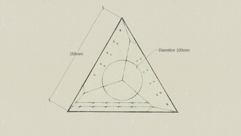
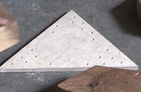
- According to the diagram, make a triangle and its tracks/holes in a plywood of thickness 9mm. Each blade's base, on the outer surface of the triangle, is represented on the triangle. The outline of the central circle does not allow the pre-drilled to enter this area which will subsequently accommodate threaded rods. The lines parallel to the sides for pre-drills (for 5mm screws) are randomly defined. This triangle is used to assemble the propeller on the inner surface.
Étape 7 - Propeller: Assembly
- Place the blade on the propeller on a good flat surface with the outer surface side visible.
- Place the disc in the center of the plywood, with the help of a drill with a centering pin.
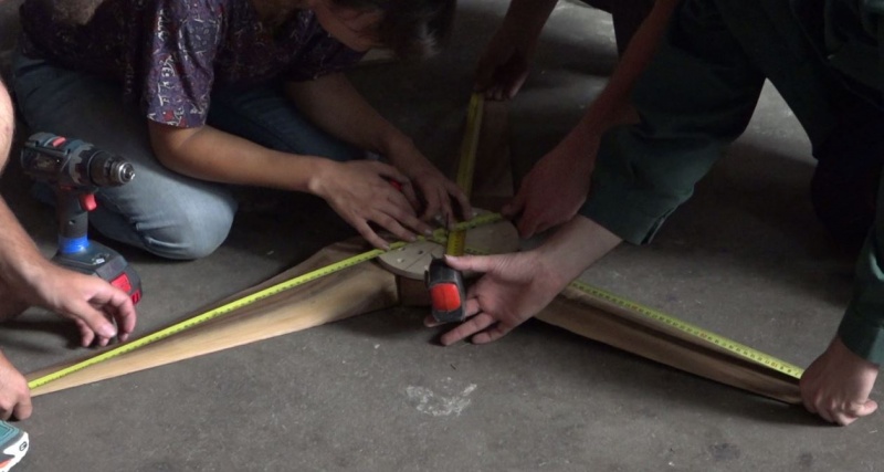
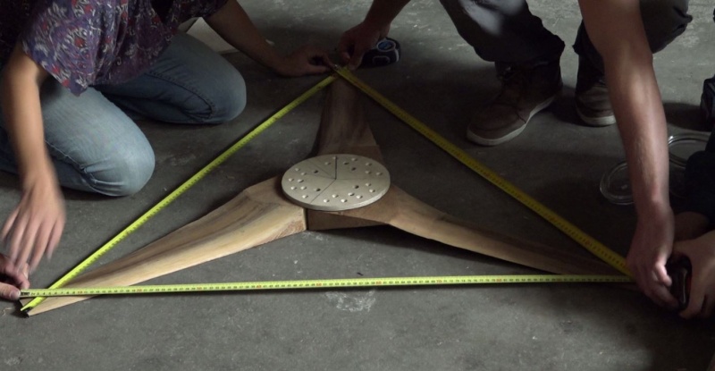
- With 3 measuring tape and 3 people, position the circle in such a way that the tip of the blade should be equidistant from the centering pin. The tip of the blade here means the tip of the leading edge.
- Once it is placed correctly in the center, maintain the circle's position and screw-in one screw for each blade so that it can still pivot.
- Then adjust the distance between every tip of the blade with a measuring tape.
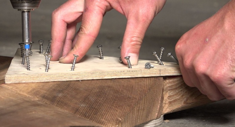
- Hold the position and then screw-in all the screws.
- Screw-in the triangle on the side intrados while taking care to place the right side of the triangle so that the pre-drills are in front of the blade foot.
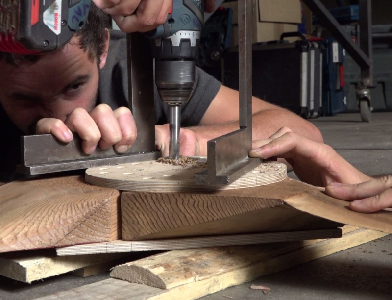
- Expand the 4 holes of 12mm on the plywood disc along the entire propeller. Use a square to ensure vertical holes.
Note: To help the propeller to fit-in on the rest of the wind turbine, it is possible to enlarge the holes of 12mm in 14mm on the thickness of the triangle and the blades, without touching the diameter 12mm of the disc.
- With an hole cutter of 60mm diameter, cut a cylinder of 30mm deep from the side extrados.
Étape 8 - Generator, stator: Preparation of the cradle.
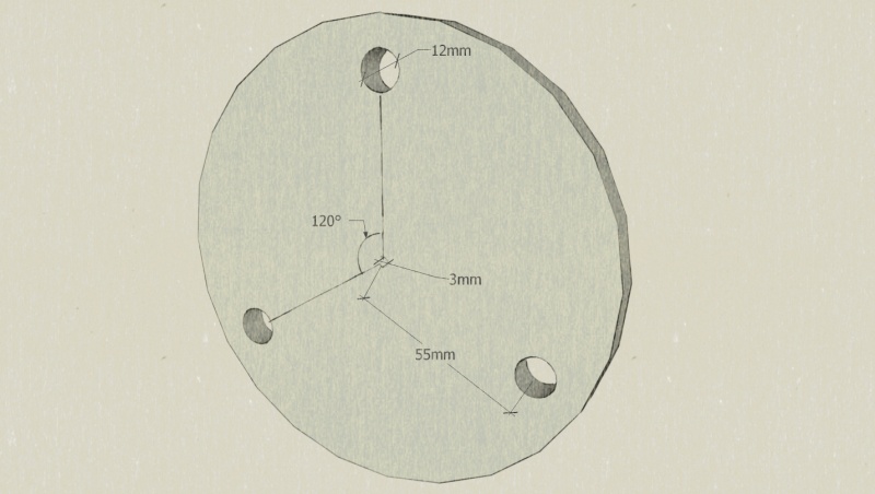
- Take a metallic disc of diameter 140mm and thickness 8mm.
- According to the diagram, drill holes at 12mm.
Note: For a precise hole, point the center with a pin, pre-drill with a drill of small diameter and then at 12mm. Choose a rotation speed adapted to material and diameter of drill. Lubricate well during drilling.
- Take a rear wheel hub of Golf, Corsa, Polo or Ibiza, it can be recovered from a scrapped car. Separate the part that attaches to the car (spindle) and the rotating part (a bell-shaped part) while careful putting aside the nuts and ball bearings.
- Draw a circle of radius slightly greater than 40mm on the metallic disc to center the spindle's base on the cradle.
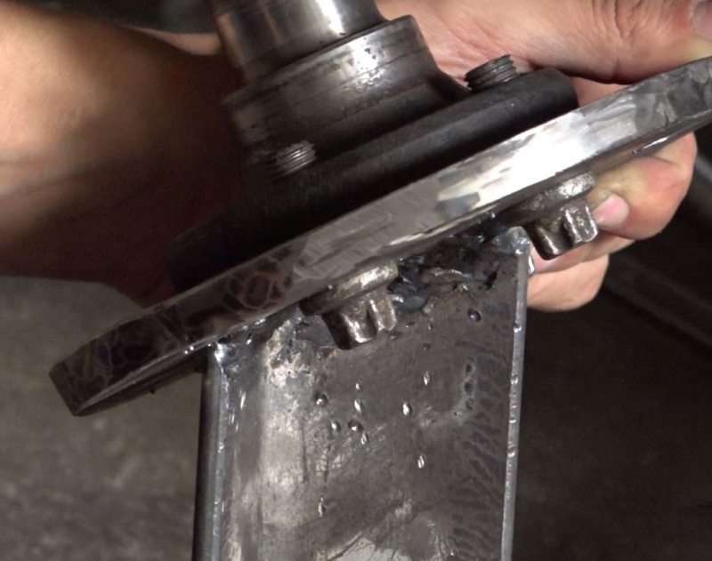
Fix the two part temporarily with a few soldering points. Make the 4 drills across the base of the spindle and the cradle.
Note: If the 4 initial screws of the spindle are in good condition, they can be recovered by drilling only the cradle and screwing directly into the base. In this case, care should be taken that the original threading should not get damaged (which is a mechanical threading and cannot be used with other screws). It is sometimes necessary to shorten these screws so as to avoid problems during assembly.
- Drill the center of the cradle with a small drill (approx 3mm). This drilling will be used when the stator is cast.
Étape 9 - Generator, stator: Preparation threaded rods stator
Note: The stator is the fixed part of the generator.
- Take a threaded rod of 12mm diameter.
- Cut 3 70mm long rods.
Notes:
1) If a clamp is used to maintain the threaded rod while cutting, wrap the threaded rod in a cloth at the jaws before tightening, to avoid damage to the screw pitch.
2) Before cutting the rod, screw a nut on the part of the rod that will be cut in order to reform the pitch of the screw at the level where it is been cut with the repeating passage of the nut.
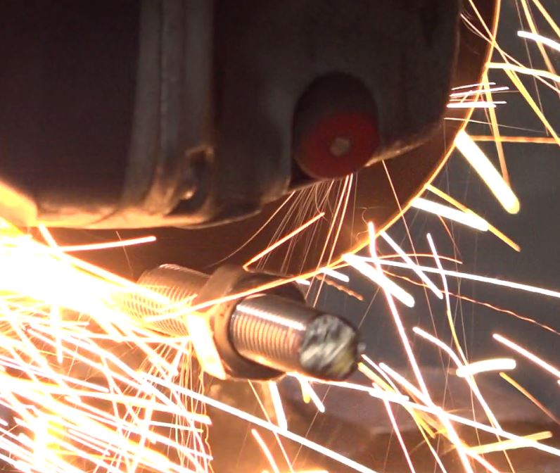
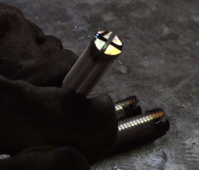
- Fendre en croix sur 10mm de long une des extrémités de chaque tige filetée.
- Set aside the cradle and the 3 threaded rods, they will be useful during the molding later.
Étape 10 - Generator, stator: Preparation of the coil.
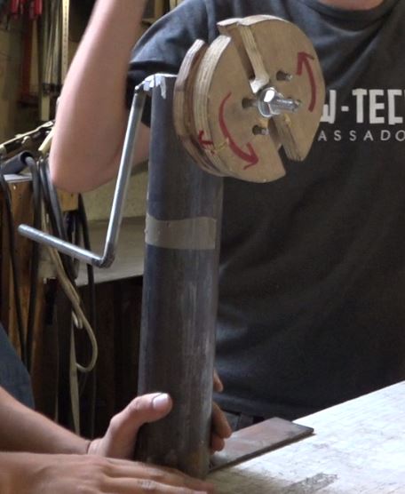
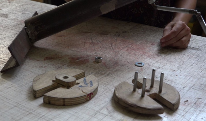
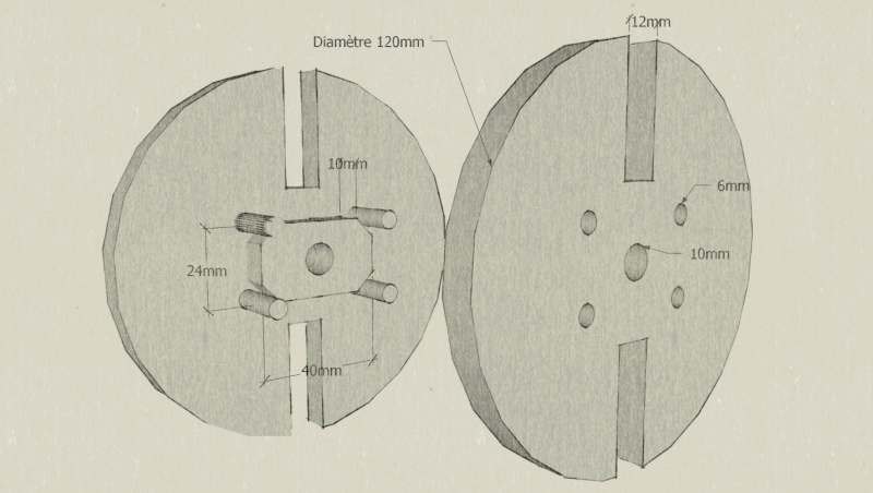
- Fabriquer le bobineur à l'aide de cornière, tube métallique, tige filetée/écrous de 10mm de diamètre, 4 gros clous de diamètre 6 et chutes de contreplaqué. Respecter les dimensions du schéma pour les découpes de contreplaqué: le rectangle défini par les bords extérieurs des 4 gros clous doit faire 46mm x 30mm.
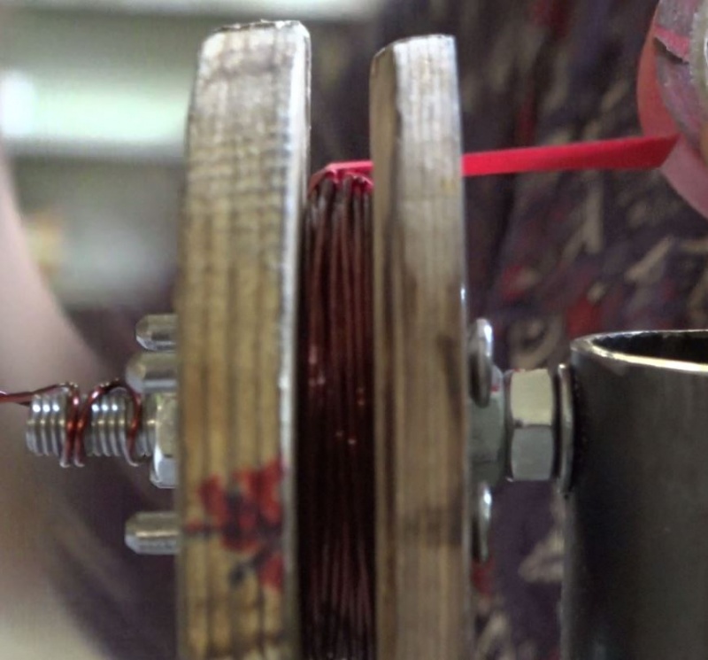
Remarque: Les bobines seront enroulées entre les deux disques de contreplaqué (épaisseur minimale 15mm), qu’on appelle les « oreilles ». Le petit rectangle de contreplaqué situé entre les deux oreilles est l’espaceur : c’est lui qui détermine l’épaisseur de la bobine. La forme intérieure des bobines est déterminée par les bords extérieurs des 4 gros clous, formant un rectangle de 46mm x 30mm. Ce rectangle correspond aux dimensions des aimants qui passeront devant.
- Après avoir réalisé la structure en métal « socle » du bobineur, découper les deux oreilles et l’espaceur selon le schéma. Réaliser les perçages avec précision. Découper une petite entaille sur une des deux oreilles pour coincer le fil de cuivre au moment du bobinage.
Remarque: Pour faciliter le glissement du fil lors du bobinage, il est possible de chanfreiner la tranche intérieure des oreilles. Faire une marque au feutre sur la tranche des deux oreilles pour compter les tours plus facilement.
Étape 11 - Generator, stator: Making of 6 coils.
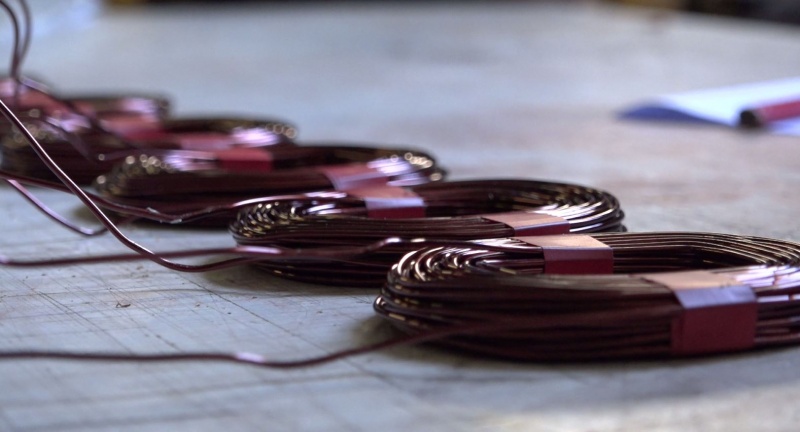
Notes: The stator is composed of 6 coils made with 76 rounds of 1.4mm diameter enameled copper wire. This allows the generator to produce maximum 200W in 12V without damaging the wires. In order to make 6 coils, 1.5kg of copper wire is required.
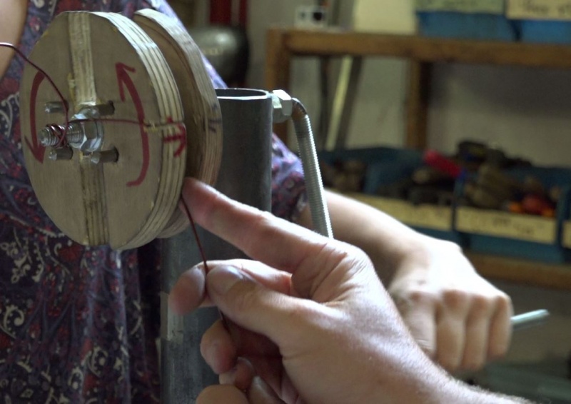
- A l'aide d'une personne et du bobineur, réaliser 1 bobine. 1 personne enroule le fil et compte les tours précisément, une personne crée une tension dans le fil et s'assure de la bonne répartition du fil sur l'épaisseur du bobineur. Si la tension dans le fil n'est pas assez importante, la bobine sera trop large.
- Laisser une marge de 30 cm de fil avant de commencer à enrouler le fil ainsi qu'à la fin.
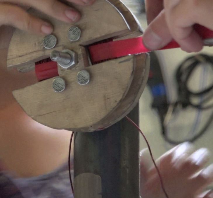
- Avant de démouler, maintenir la bobine avec du scotch d'électricien. Il est possible de s'aider d'un réglet pour passer le scotch entre l'espaceur et la bobine, grâce aux grandes fentes sur les oreilles prévues à cet effet.
- Make 6 coils in total.
Étape 12 - Generator, stator: "Star" mounting
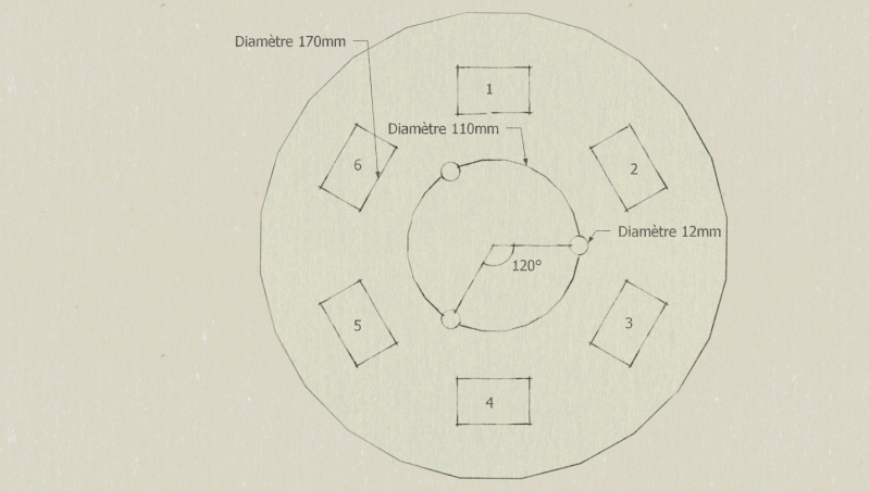
- Réaliser dans une chute de contreplaqué le gabarit en schéma. Tracer l'emplacement qui accueillera les 3 tiges filetées au centre ainsi que l'emplacement du centre de chacune des bobines. Il y a 6 bobines, l'écart entre chaque est de 60°.
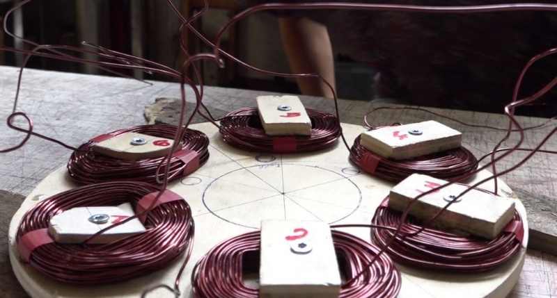
- A l'aide de 6 chutes de contreplaqué d'environ 50mm x 25mm, fixer chaque bobine à son emplacement sur le gabarit. Numéroter chaque bobine de 1 à 6 comme sur le gabarit.
Remarque: Il est impératif que toutes les bobines soient positionnées avec les spires tournant dans le même sens, soit horaire soit anti-horaire. Si ce point n'est pas respecté, la génératrice ne fonctionnera pas comme prévu.
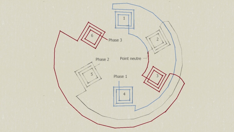
- Link the coils according to the diagram while taking care of letting the center and the placement of the threaded rods free.
- Connect the inputs of the coils 1,2 et 3: this is the neutral point.
2) Connect the output of 1 to the input of 4.
3) Connect the output of 2 to the input of 5.
4) Connect the output of 3 to the input of 6.
- Cut the extra wire from each coil.
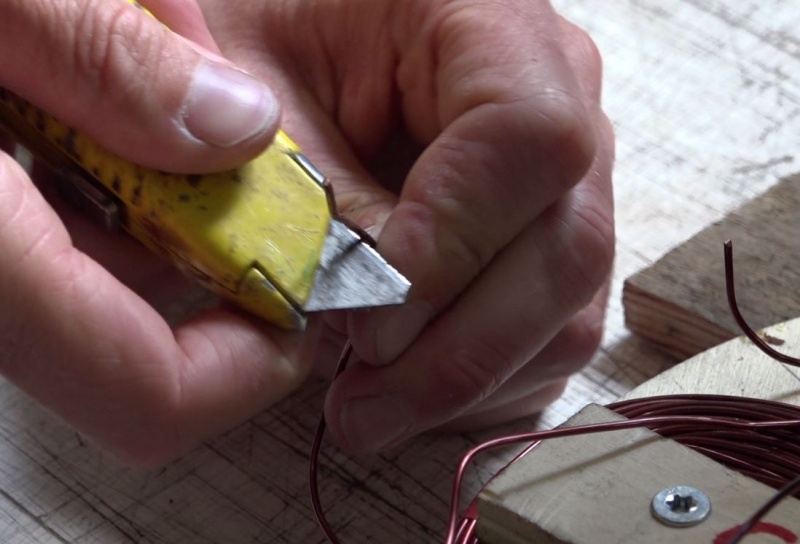
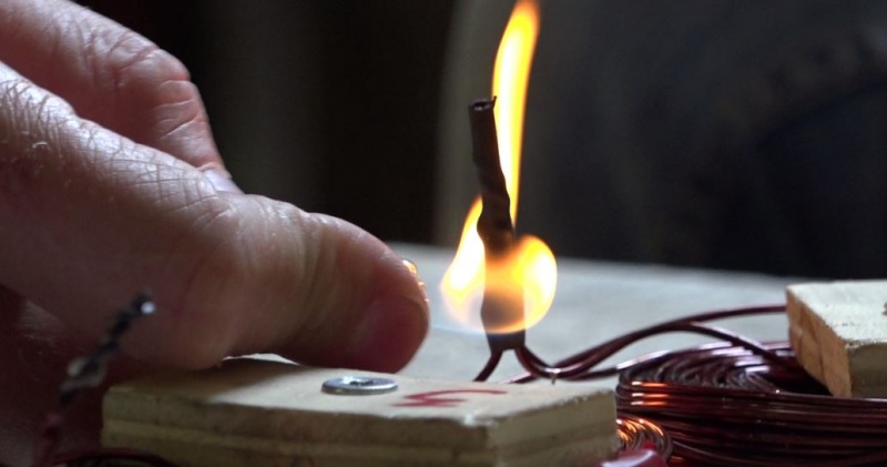
- With the help of the cutter, remove the enamel up to 3cm on every wire. The surface of the wire should be clearer and more matte.
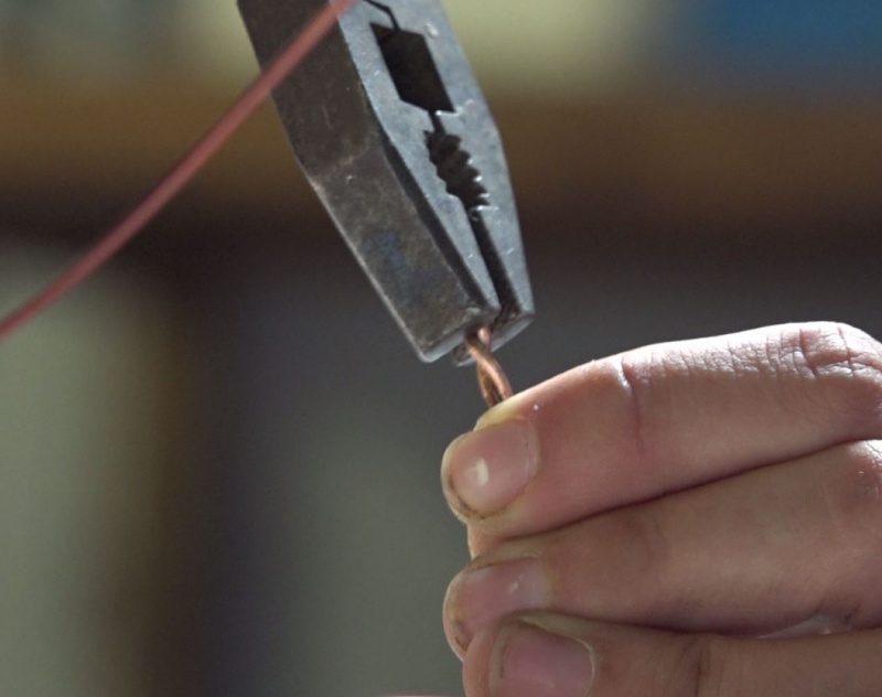
- Twist the wires of each connection.
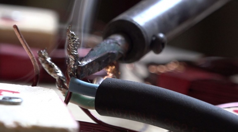
- Souder les connexions avec un fer à souder et de l'étain. Pour une belle soudure, faire chauffer la zone à souder puis déposer l'étain sur le fil pour qu'il fonde et migre dans les interstices.
- Protect each weld with heat shrink tube.
Étape 13 - Generator, stator: Three-phase cable
- Take 60cm of flexible 3-wire cable, 2.5mm².
- Souder les sorties des bobines 4, 5 et 6 formant les 3 phases puis les protéger avec de la gaine thermorétractable. Une attention particulière doit être apportée à l'isolation, les fils pouvant se toucher.
Étape 14 - Generator, stator: Making the stator mould
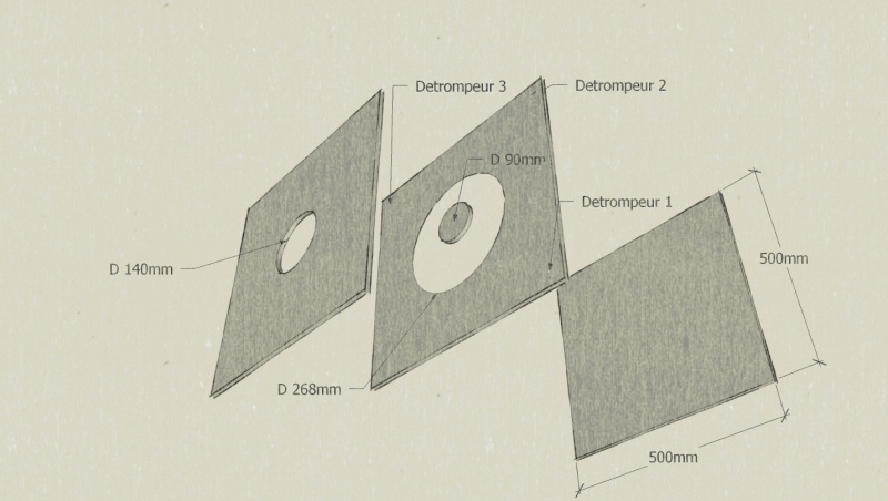
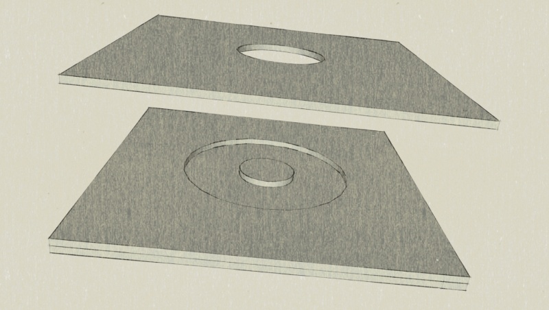
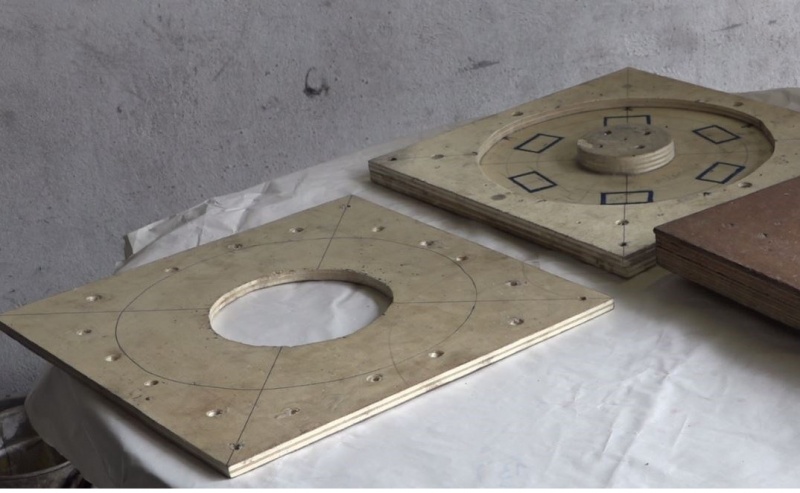
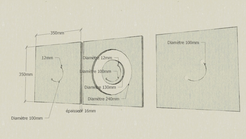
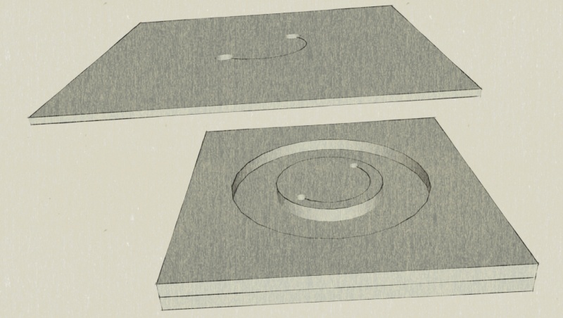
- Dans du contreplaqué de 10mm d'épaisseur réaliser le moule selon schéma.
Il se décompose en 4 parties: le socle, la bordure, l'îlot central et le couvercle. Bien penser à percer 3 détrompeurs pour le bon alignement du couvercle au moulage.
- Screw/glue the border and central block to the base.
- Dessiner l'emplacement de chaque bobine dans le moule. Il est possible de s'aider du gabarit précédemment réalisé.
Étape 15 - Generator, stator: Preparation of the molding.
Remarque: Cette étape fait intervenir des éléments dangereux (résines, fibres, etc) Porter des gants latex et lunettes de protection jusqu'à la fin du moulage.
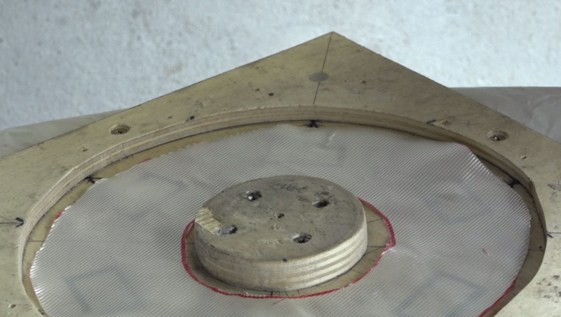
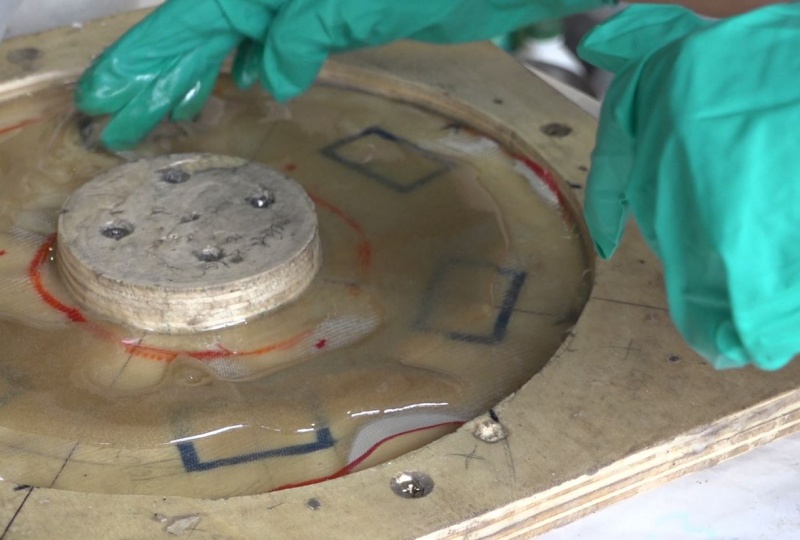
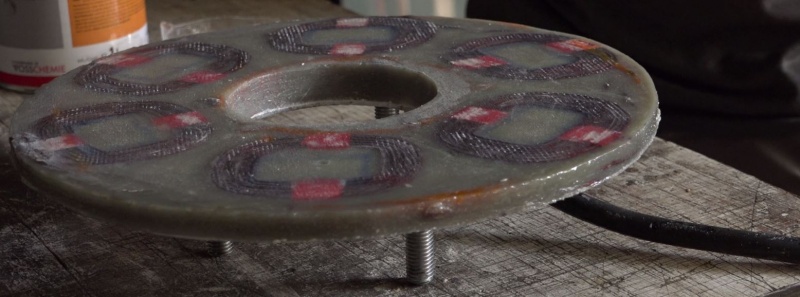
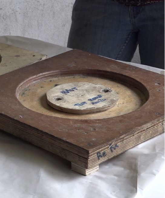
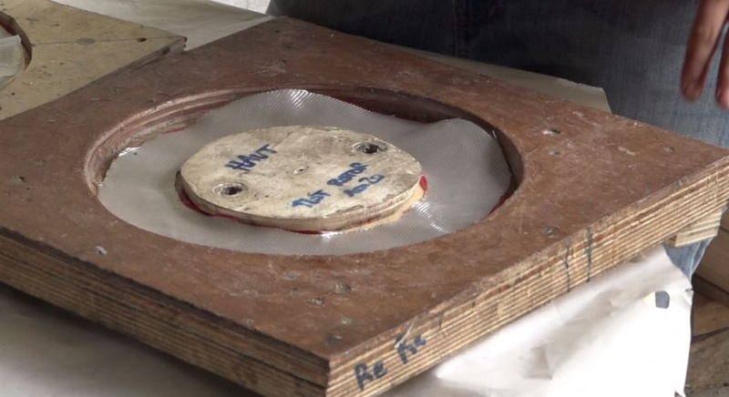
- Préparer 2 disques de fibre de verre ayant la forme du moule puis les mettre de coté. Prévoir une marge de diamètre au niveau de l’îlot (cf photo).
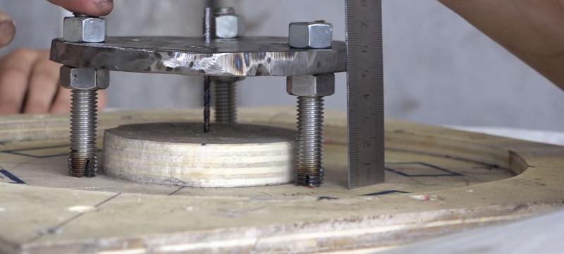
- Prepare the 3 threaded rods by screwing them on the cradle. Adjust the parallelism of the rod well.
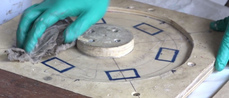
- A l'aide de cire de démoulage/wax, bien cirer l'ensemble du moule, intérieur/extérieur, le couvercle intérieur/extérieur, une dizaine de vis qui serviront à fixer le couvercle ainsi que 3 pions pour les détrompeurs.
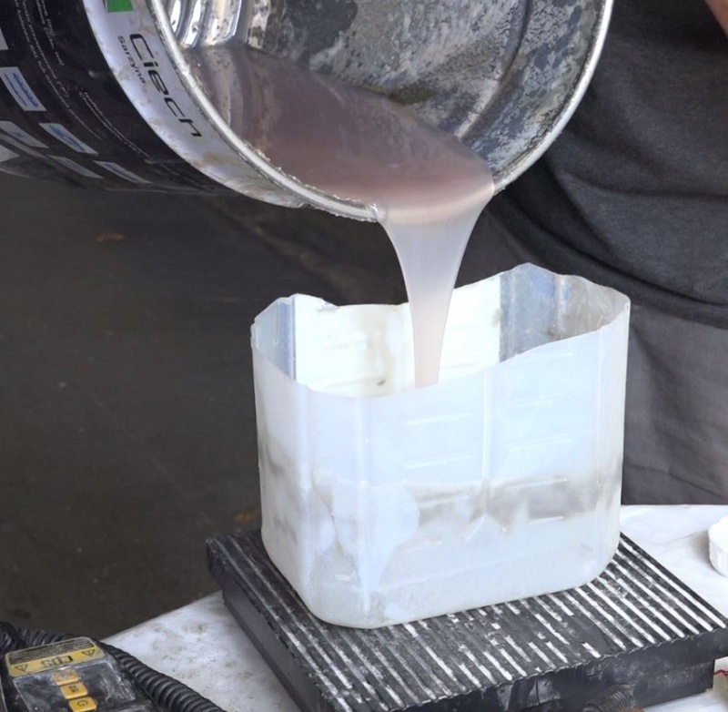
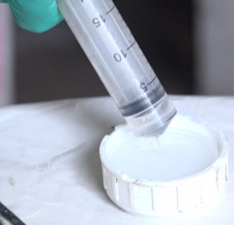
- Préparer 2 bacs de 150g de résine polyester et 2 seringues de 2,25ml du catalyseur associé.
- Préparer un bac de 300g de résine mélangée avec 150g de talc ainsi qu'une seringue de 4,5ml de catalyseur.
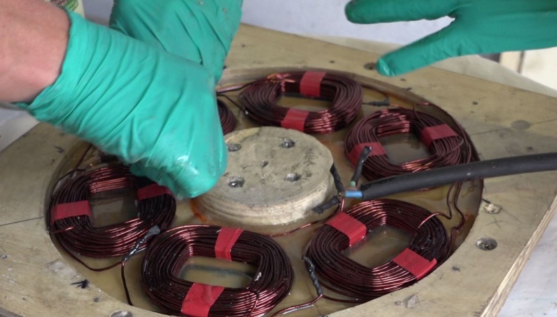
- Préparer l'ensemble du montage bobine, débridé du gabarit, afin qu'il soit prêt à installer dans le moule.
Étape 16 - Generator, stator: Molding.
- Verser la seringue associée dans un des bacs de 150g de résine et mélanger énergiquement.
- Pour some of this resin into the bottom of the mold.
- Put one of the two glass fiber discs to the bottom of the mold and soak well with resin.
- Placer soigneusement le montage des bobines dans le moule. Chaque bobine doit être bien à sa place et aucun fil ne doit dépasser du moule. C'est une étape délicate. finir de verser le premier bac de résine.
- Pour the associated syringe into the 300g resin tray + talc. Mix vigorously.
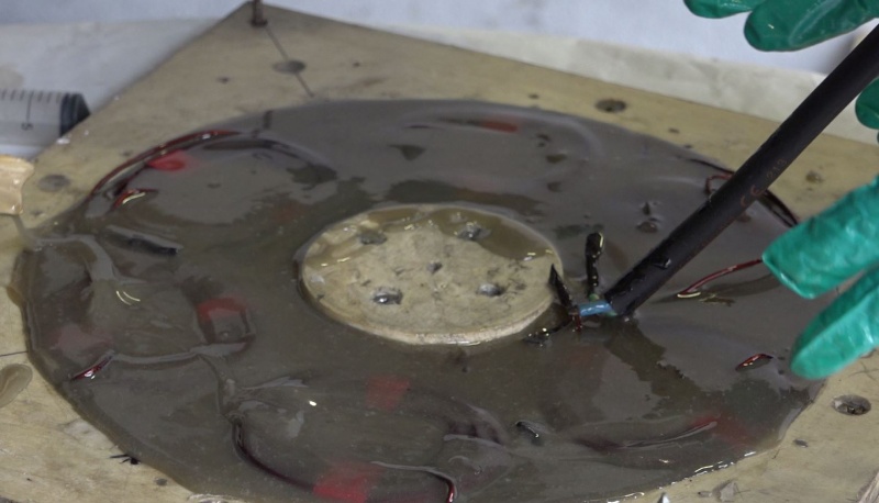
- Pour the content on the assembly.
Remarque: le talc permet non seulement de charger la résine avec un matériau peu cher mais également de diffuser la chaleur lors du séchage de la résine et durant le fonctionnement futur de l'éolienne afin de ne pas endommager le stator.
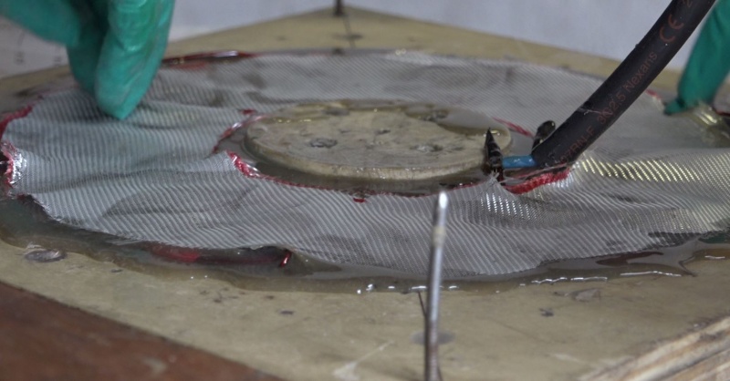
- Positionner le second disque de fibre de verre et bien l'imbiber.
- Préparer et verser le dernier bac de résine. Il vaut mieux avoir un surplus de résine que pas assez.
- Positionner le couvercle grâce aux détrompeurs et le brider grace aux vis cirées.
- Positionner délicatement les tiges filetées liées au berceau, la partie fendue dans la résine. S'aider d'un foret comme centreur entre l’îlot et le berceau.
- Au besoin, attacher à l'aide d'un colson le câble triphasé pour qu'il sorte correctement du stator.
- Laisser durcir (cela peut prendre plusieurs heures). puis démouler, ébavurer et vernir ou peindre.
Étape 17 - Génératrice, rotor: Préparation du disque métallique.
propeller
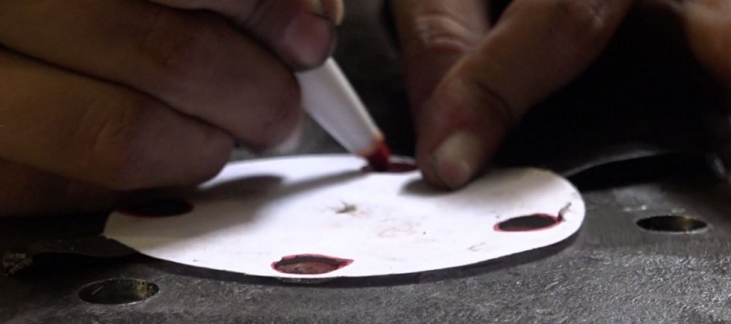
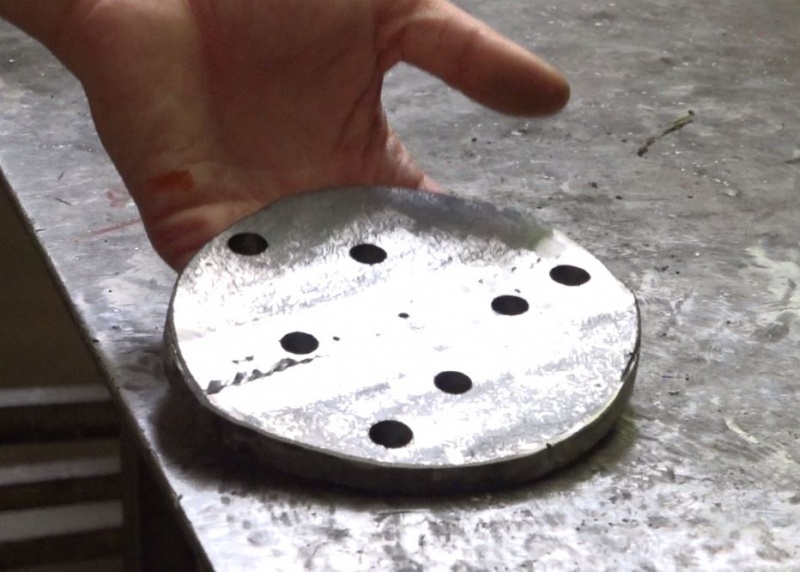
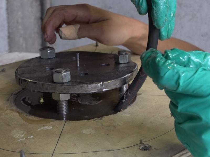
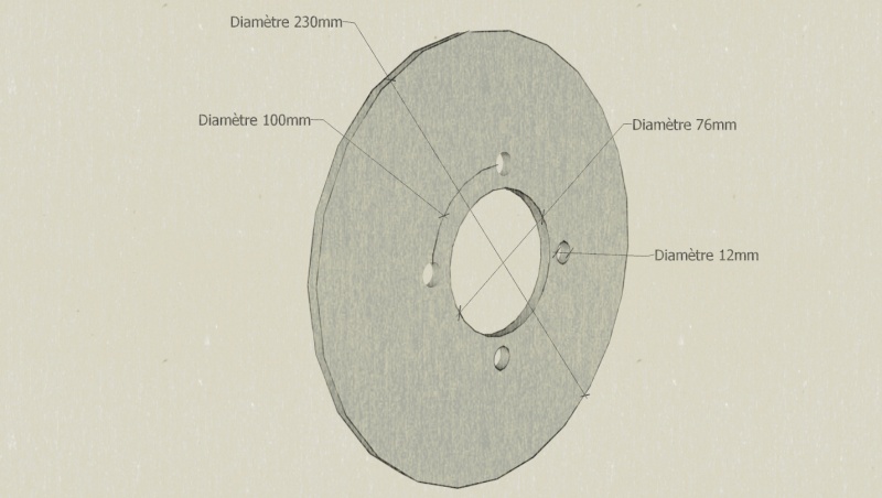
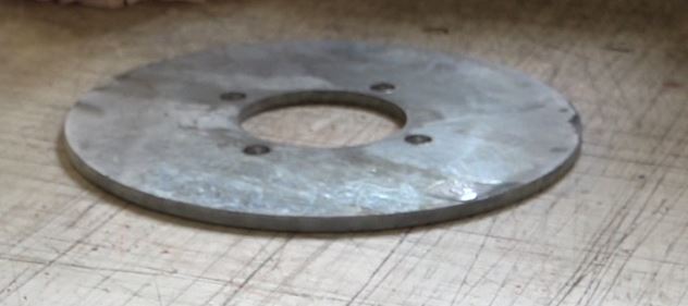
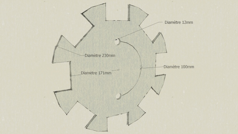
- Se munir d'un disque en acier épaisseur 6mm, si possible galvanisé, de diamètre 230mm et le préparer selon schéma. Les 4 trous de 12mm de diamètre sont répartis sur chaque quart du cercle de 100mm de diamètre.
Remarques:
1) Il est impératif que le disque soit en acier pour qu'il puisse conduire les champs magnétiques. Cela ne fonctionnera pas avec de l'alu ou de l'inox par exemple.
2) Il peut être plus facile de se fournir le disque tout préparé auprès d'artisans qui disposent d'outils de découpe précise (plasma, laser).
Étape 18 - Génératrice, rotor: Préparation de la cloche du moyeu
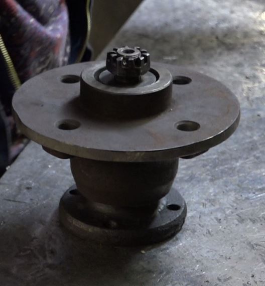
- Se munir de la cloche du moyeu mise de coté auparavant (cf étape: "Génératrice, stator: Préparation du berceau").
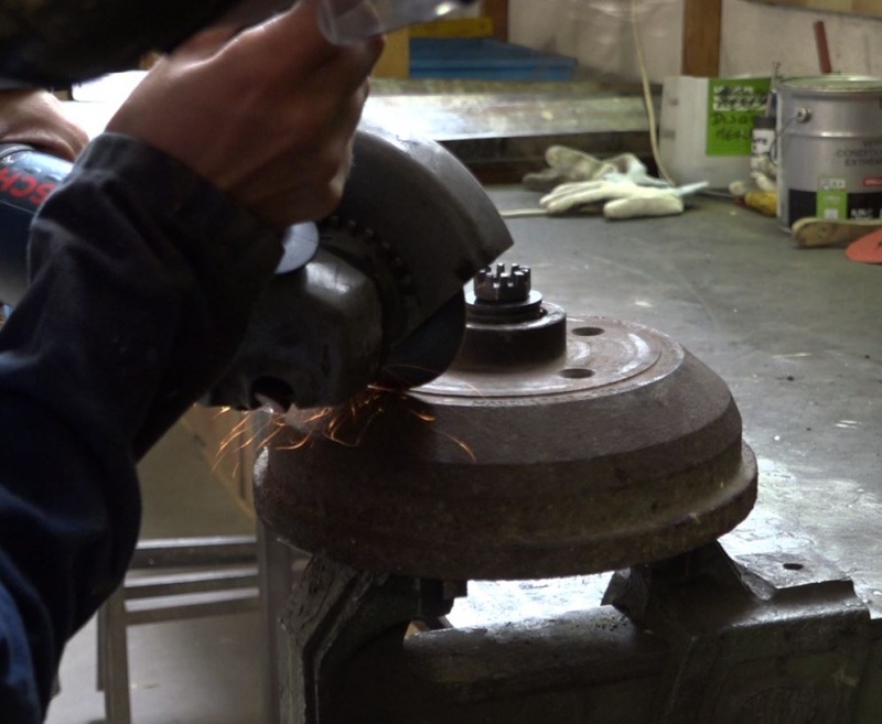
- Découper la cloche à la meuleuse de façon à ne garder que la platine plate avec les perçages.
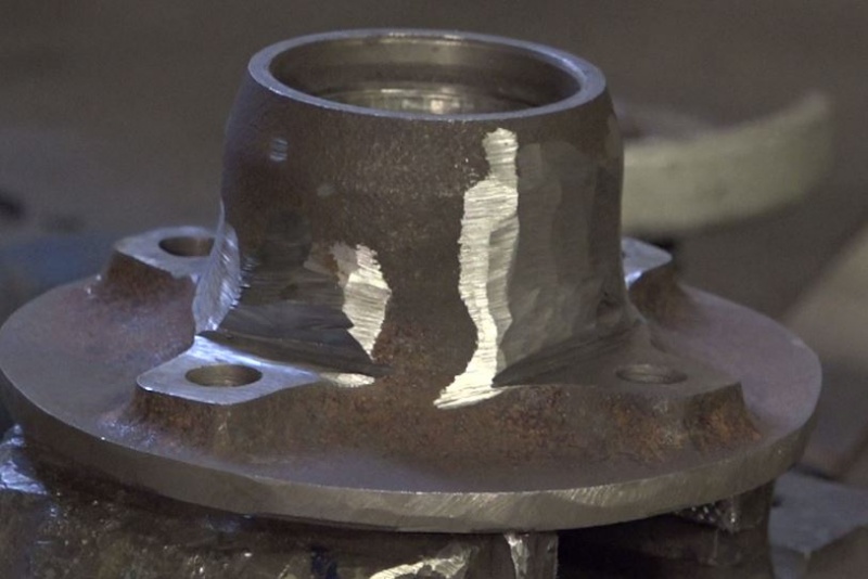
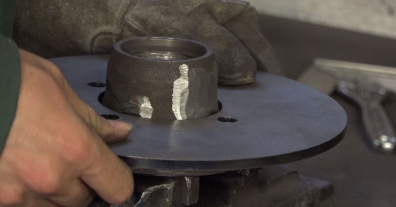
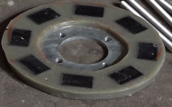
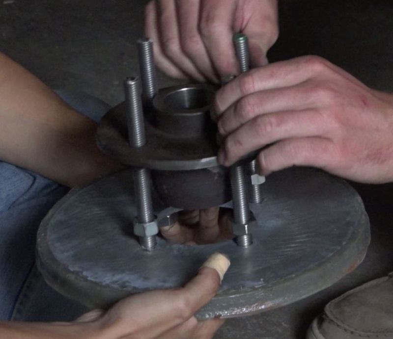
- Meuler la cloche de telle sorte que le disque en acier puisse s'insérer parfaitement à plat sur les 4 appuis percés. (cf photos)
Étape 19 - Génératrice, rotor: Préparation du gabarit
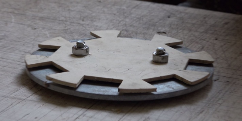
- Dans une chute de contreplaqué fin, réaliser le gabarit selon schéma.
- Dégraisser le disque en acier avec du dégraissant.
- Se munir de deux boulons de 12mm avec rondelles.
- Visser le gabarit sur le disque en acier en intercalant des rondelles.
Étape 20 - Génératrice, rotor: Collage des aimants
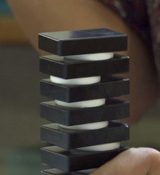
Remarque: Cette étape consiste à coller des aimants très puissants sur le disque en acier en alternant les pôles des aimants. Si l'alternance n'est pas respectée, la génératrice ne fonctionnera pas et risque des dommages.
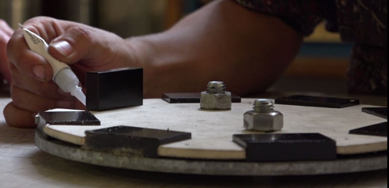
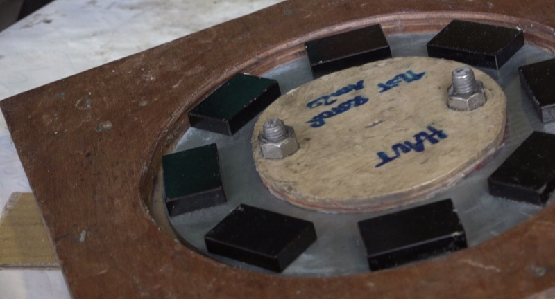
- Se munir de 8 aimants néodymes 46mm x 30mm x 10mm.
Remarque: Faire très attention durant la manipulation de ces aimants. Etant très puissants, ils peuvent endommager les appareils électroniques, attirer des objets métalliques en tout genre et pincer très fort. Ils sont également fragiles et peuvent se casser durant les chocs.
- Poser un point de super glue dans une première encoche et coller le premier aimant. Faire attention à ce que l'aimant soit parfaitement calé dans l'encoche.
- Prendre un deuxième aimant dans son poing, le positionner au dessus du premier.
1) S'il y a répulsion, le coller dans l'encoche adjacente en conservant bien ce sens: les 2 aimants ont les polarités positionnées de manière opposée.
2) S'il y a attraction, le retourner dans sa main, vérifier qu'il y a maintenant répulsion, et le coller dans l'encoche adjacente.
- Appliquer la même procédure avec tous les aimants. Une fois terminé, les faces visibles des aimants sont alternées comme suit: 1) Nord , 2) Sud, 3) Nord, 4) Sud, 5) Nord, 6) Sud, 7) Nord, 8) Sud ou inversement.
- Laisser sécher puis retirer le gabarit.
Étape 21 - Génératrice, rotor: Préparation du moule
- Réaliser le moule du rotor dans du contreplaqué de 16mm d'épaisseur pour le socle et la bordure, le couvercle peut être moins épais. Les diamètres des trous dans le couvercle doivent permettre le passage d'écrou pour vis de 12mm.
- Visser/coller le socle et la bordure ensemble.
Étape 22 - Génératrice, rotor: Préparation du moulage
Remarque: Cette étape fait intervenir des éléments dangereux (résines, fibres, etc) Porter des gants latex et lunettes de protection jusqu'à la fin du moulage.
- Préparer 1 disque de fibre de verre ayant la forme du moule puis le mettre de coté.
- A l'aide de cire de démoulage/wax, bien cirer l'ensemble du moule, intérieur/extérieur, le couvercle intérieur/extérieur ainsi que 2 boulons de 12mm assez longs pour traverser l'ensemble du moule.
- Préparer 2 bacs de 150g de résine polyester et 2 seringues de 2,25ml du catalyseur associé.
- Préparer un bac de 300g de résine mélangée avec 150g de talc ainsi qu'une seringue de 4,5ml de catalyseur.
- Positionner le disque en acier dans le moule, positionner l'ilot par dessus et visser l'ensemble avec les boulons graissés.
Étape 23 - Génératrice, rotor: Moulage
- Verser la seringue associée dans un des bacs de 150g de résine et mélanger énergiquement.
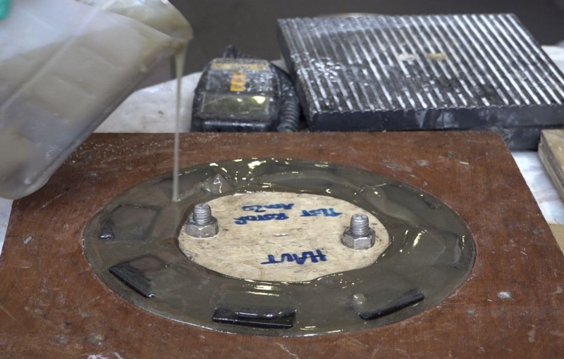
- Verser cette résine dans le moule.
- De la même manière, préparer et verser la résine + talc.
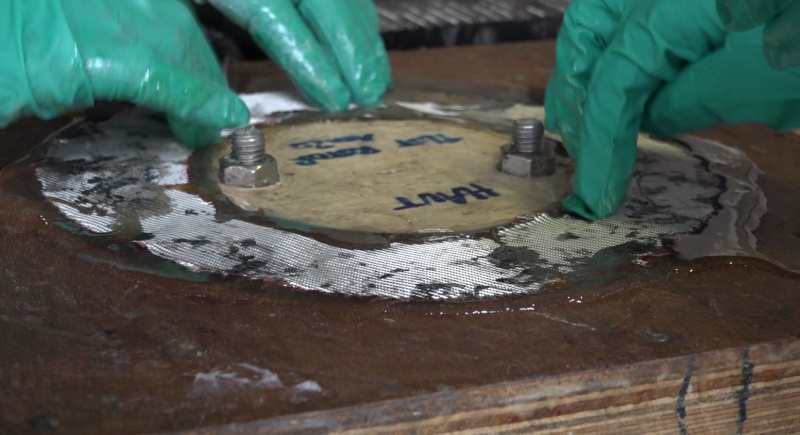
- Positionner le cercle de fibre et bien l'imbiber.
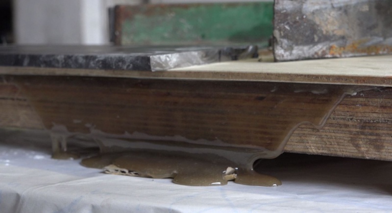
- Au besoin, préparer et verser le dernier bac de résine. Il vaut mieux avoir un surplus de résine qui déborde.
- Positionner le couvercle et poser de lourdes pièces métalliques dessus (cornières, tubes, etc) la force d'attraction des aimants permet de presser le surplus de résine.
- Laisser durcir, démouler, ébavurer et vernir ou peindre.
Étape 24 - Structure, Nacelle
- Se munir de:
1) Une cornière de 206mm (50x50x6mm).
2) Un tube diamètre ext 42,2mm, longueur 100mm: Pivot éolienne.
3) Un tube diamètre ext 33,4mm, longueur 150mm: Pivot Safran.
4) Le berceau précédemment réalisé.
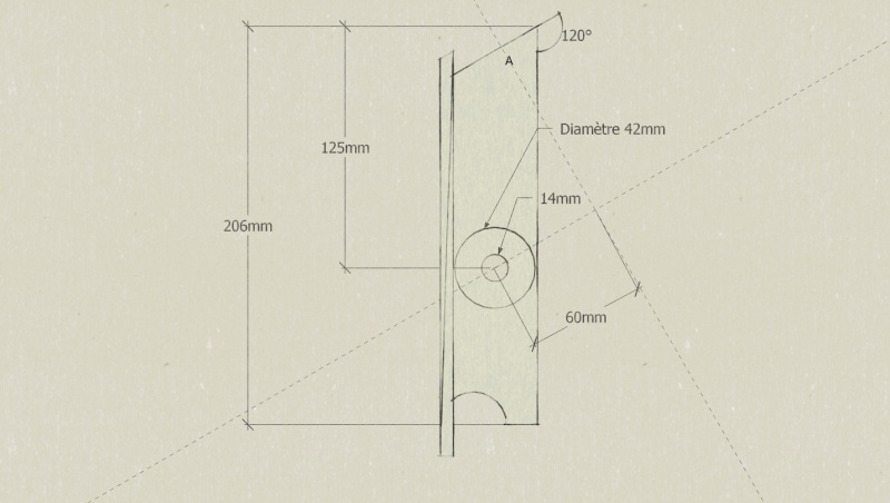
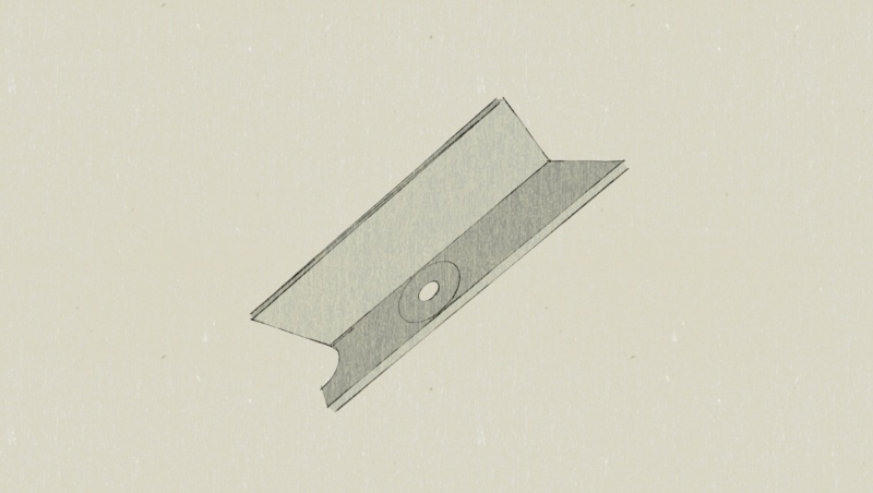
- Préparer la cornière selon schéma.
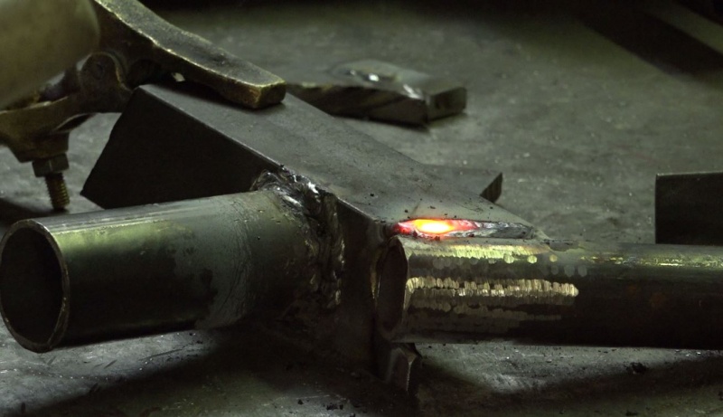
- Souder le tube pivot éolienne sous la cornière, bien centré avec le trou de 14mm et bien perpendiculaire à la cornière.
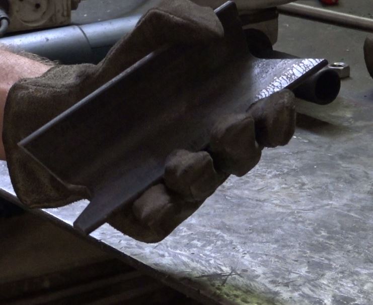
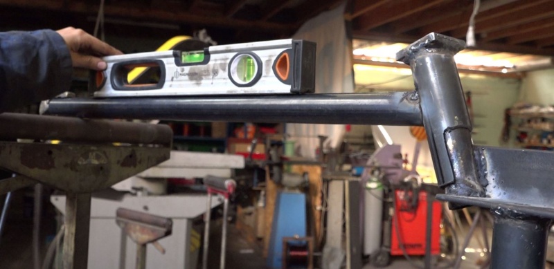
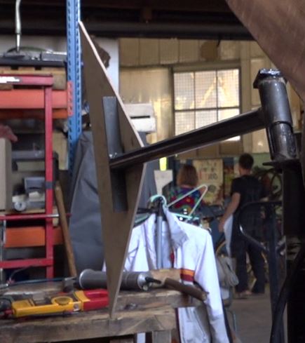
- Souder le tube pivot safran à l'arrière de la cornière (cf photo).
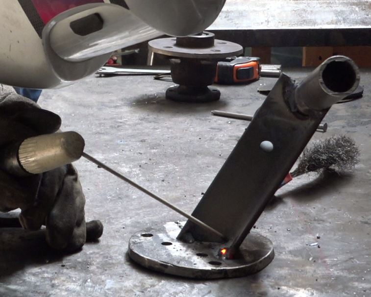
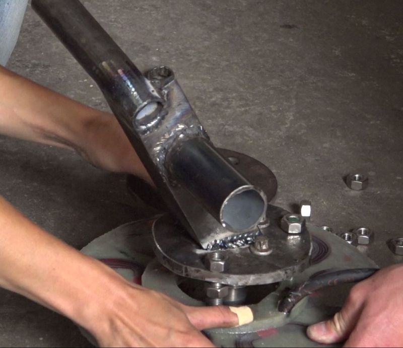
- Souder le berceau en bout de cornière en centrant le centre du berceau sur le point A. Pour la soudure, il est nécessaire de sacrifier un des 4 trous permettant la fixation de la fusée. Ce n'est pas un problème tant que tous les autres restent bien accessible.
Remarque: La chaleur dégagée par la soudure peut avoir tendance à faire travailler le métal, déformer les pièces et les positions choisies. Pour éviter ce problème, réaliser quelques points de soudure à quelques endroits stratégiques sur le périmètre de la soudure puis tirer le cordon soudure.
Étape 25 - Structure, Safran
- Se munir de:
1) Un tube diamètre ext 42,2mm, longueur 130mm: Pivot safran.
2) Un fer plat 50 x 50 x 6mm: Couvercle du pivot safran.
3) Un tube diamètre ext 33,4mm, longueur 700mm: Queue du safran.
4) Une cornière 30 x 30 x 5, longueur 250mm: Support safran.
5) Un contreplaqué taillé selon les envies de chacun, d'épaisseur 6mm et de 0,1m² de surface. (par exemple un triangle rectangle de hauteur 300mm et base 600mm): le Safran.
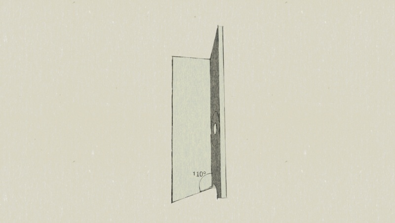
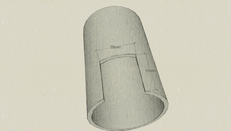
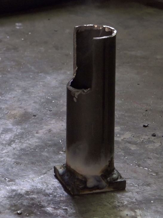
- Sur le pivot safran ouvrir une encoche selon schéma.
- Souder le couvercle sur l'extrémité opposé à l'encoche du pivot safran.
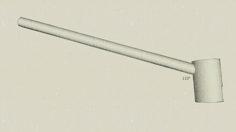
- Sur le tube queue de safran, réaliser une gueule de loup en s'aidant d'un patron permettant une soudure à 110° du pivot safran.
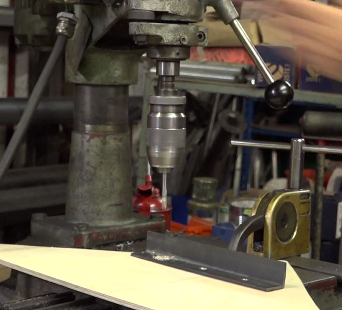
- Percer la cornière support en 3 points permettant l'attache du Safran avec des boulons de diamètre 6mm.
- Souder perpendiculairement la cornière support en bout de queue de safran.
Étape 26 - Assemblage, Génératrice
- Visser la fusée du moyeu sur le berceau de la nacelle.
- Visser un écrou sur chaque tige du stator.
- Visser le stator sur le berceau.
- Préparer 4 tiges filetées diamètre 12mm, longueur 140mm. (cf méthode: étape "Génératrice, stator: Préparation tiges filetées stator").
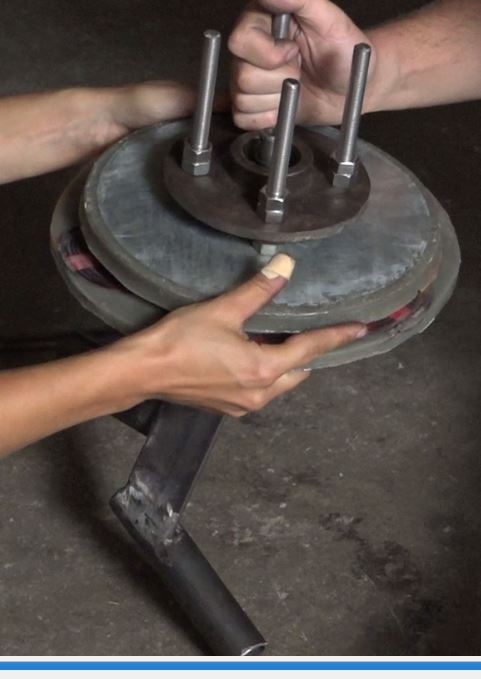
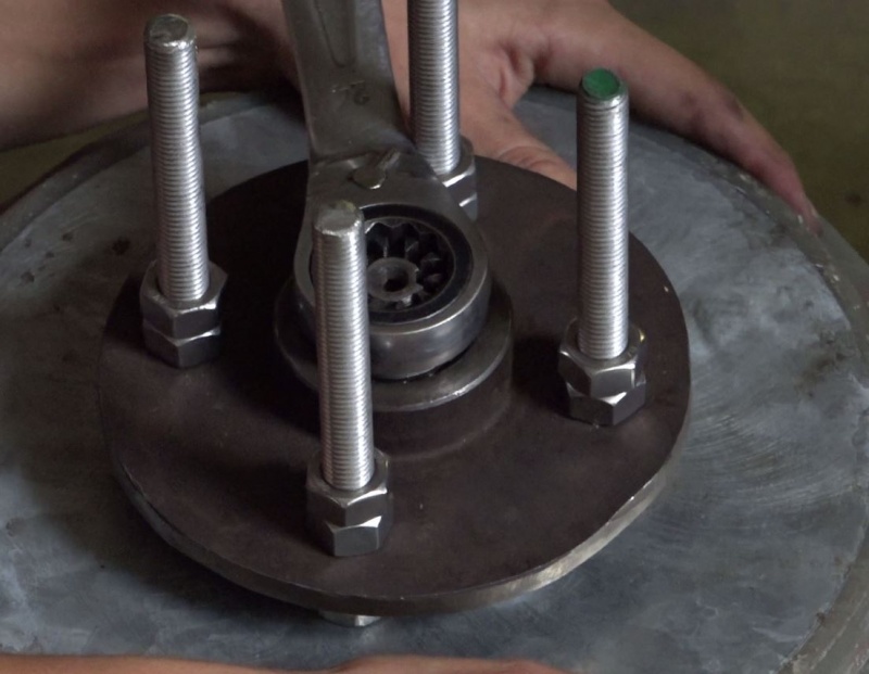
- Fixer le rotor sur la cloche du moyeu avec les 4 tiges filetées et 16 écrous.
- Emboîter la cloche du moyeu sur la fusée en repositionnant soigneusement les roulements à billes et écrous de serrage (à serrer au maximum puis desserrer d'un quart de tour). Le système doit tourner librement.
- Ajuster l'écart entre le rotor et le stator en jouant avec les écrous du stator. L'espace doit être d'environ 1mm.
Étape 27 - Assemblage final et test de production
- Positionner la nacelle sur un mat d'essai.
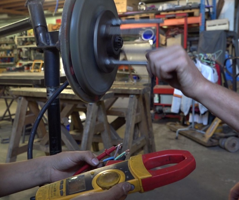
- A l'aide d'une personne, faire tourner la génératrice à 1 tour/seconde. Il est possible d'utiliser un métronome. Régler un voltmètre sur alternatif et mesurer la tension entre chaque phase. La valeur doit être proche de 1,9V. Si ce n'est pas le cas, vérifier l'écart entre stator et rotor.
propeller
- Installer le safran sur le pivot.
Étape 28 - Équilibrage des pales.
Étape 29 - Graissage de l'éolienne
Étape 30 - Installation redresseur 12V continue
Remarque: Afin de pouvoir chargé une batterie 12V, il est d'abord nécessaire de transformer le courant alternatif produit par chaque phase en un courant continu.
- Se munir d'un redresseur de tension triphasé alternatif à monophasé continu.
- Souder chacune des phases du câble de sortie sur chaque borne d'entrée du redresseur.
- Souder un câble monophasé sur les 2 bornes de sortie du redresseur.
- Protéger le système dans un boitier étanche et le fixer sur le corps de l'éolienne.
Remarque: Il sera nécessaire d'installer un contrôleur de charge entre l'éolienne et la batterie.
Étape 31 - Contenu pédagogique à télécharger
Vous pouvez télécharger une fiche pédagogique créée par le Low-tech Lab dans la partie "Fichiers" du tutoriel (onglet au niveau de la section "Outils-Matériaux").
Notes et références
- Pack tutoriel réalisé par Camille Duband et Pierre-Alain Lévêque, équipe Low-tech Lab, Septembre 2017.
- Les éoliennes developpé par Hugh Piggott vont de 200W à 2000W.
- Site de Hugh Piggott, inventeur de l'éolienne, informations en Anglais.
- Site de Tripalium, pour y trouver informations et stages de construction, en Français.
- Lien pour l'achat du manuel tripalium pour une construction complète de l'éolienne à la distribution électrique sur toute la gamme d'éoliennes.
Published



 Français
 English
 Deutsch
 Español
 Italiano
 Português