Description
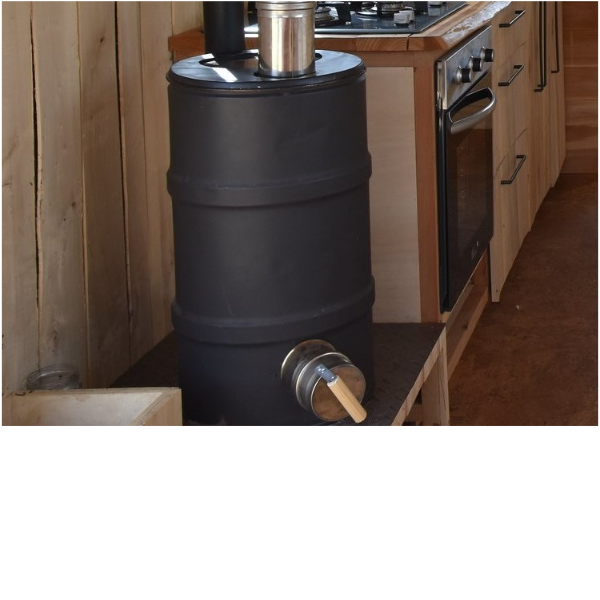
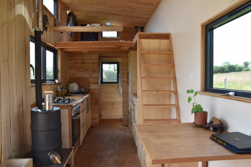
Semi-removable inertia mass stove. A mass storage stove or ‘heat storage stove’ is a primary heating device. Its mass, which is made up of heavy material (stone, brick and concrete), stores energy from a fire that burns once during the day (lasting between 1 and 3 hours). Once the fire has gone out, it then continues to give out heat over a prolonged period (for up to 24 hours). Its mass provides thermal inertia which helps to keep an even temperature inside a building (which is why these stoves are often also called “inertia stoves”). The whole of the quantity of wood needed to heat the dwelling is burnt in one go, making it burn hotter which allows complete and more environmentally-friendly combustion. It is a storage device which is designed to absorb the bulk of the energy that is generated from combustion and exhaust gases, which cool down considerably once out of the stove. Accumulated heat is mainly diffused by radiation and, in a few cases, by convection. This particular type of heating, i.e. that uses radiation, is best located in the centre of the dwelling and therefore, most mass stoves these days are positioned in the main room which opens out onto the lounge, dining room and kitchen. As yield tends tend to be in the majority of cases higher than 80%, these stoves are considered to be one of the most efficient wood-fuelled heating devices. Watch the tutorial video here [1]
Sommaire
Sommaire
[masquer]- 1 Description
- 2 Sommaire
- 3 Video d'introduction
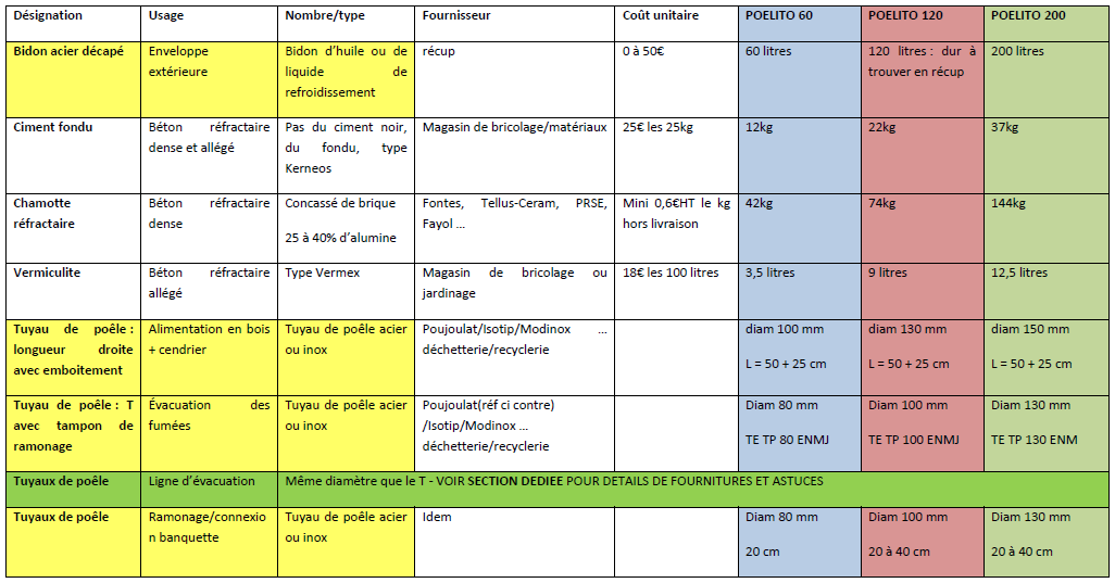
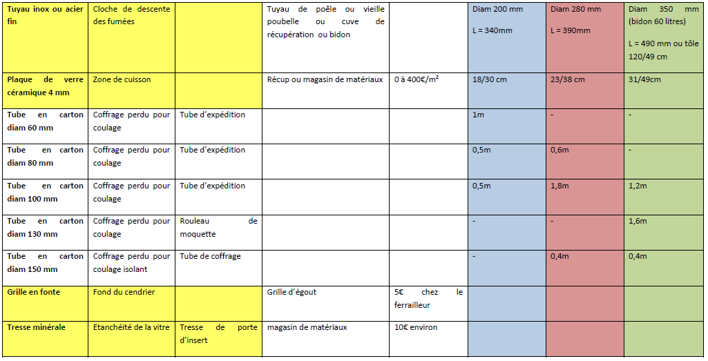
- 4 Étape 1 - Provision of Materials
- 5 Étape 2 - How the Device is made up:
- 6 Étape 3 - Sizingː
- 7 Étape 4 - Fundamental Health and Safety Rules
- 8 Étape 5 - Different types of Concrete: how to make them up and what goes in them.
- 9 Étape 6 - Preparing the drum
- 10 Étape 7 - Making the Ash Tray and Smoke Exhaust Holes
- 11 Étape 8 - Fitting the Ash Tubes and Smoke Exhaust
- 12 Étape 9 - Fitting the Moulds
- 13 Étape 10 - Making the stopper for the ash tray
- 14 Étape 11 - Casting the protective bottom
- 15 Étape 12 - Making the Moulds
- 16 Étape 13 - Positioning the Moulds.
- 17 Étape 14 - Pouring the Refractory Concrete
- 18 Étape 15 - Removing the Moulds
- 19 Étape 16 - How to Make the Wood Feed Pipe.
- 20 Étape 17 - How to make the Wood Feed Stopper
- 21 Étape 18 - Making the Grate
- 22 Étape 19 - How to Make the Heat Riser.
- 23 Étape 20 - Making the Bell Chamber
- 24 Étape 21 - Cutting out the glass
- 25 Étape 22 - Cutting out the lid
- 26 Étape 23 - Painting
- 27 Étape 24 - Installation
- 28 Étape 25 - Filling it up with sand
- 29 Étape 26 - Fitting the glass
- 30 Étape 27 - Directions for use
- 31 Étape 28 - Maintenance
- 32 Commentaires
Youtube
Matériaux
Metalwork
- Metal drum
* Pipework (tubes of differing diameters and T-tube)
- Sewer grate
Ironmongery:
- Self-tapping screws,
- Nuts and bolts
Concrete:
- Tamper for packing down and applying the concrete,
- Wire,
- An old cloth to put in the drum to deaden the noise whilst you are working.
Moulds:
- Plastic packaging (cellophane),
- Gaffer tape
- Masking tape,
- Corrugated cardboard,
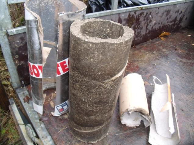
- Cardboard tubes of 80, 100, 130mm diameters respectively
Outils
Health and Safety:
- Gloves,
- Goggles,
- Ear defenders/ earplugs,
- Dust masks
- First aid kit containing saline solution in case cements gets into eyes.
For Marking/Measuring:
- Tape measure,
- Pencil,
- Marker
- String (2 metres approx.),
- Spirit level
For the Metalwork:
- Hammer/sledgehammer/chisel,
- Pincers
- Adjustable pliers
- Tin snips (often more practical that using an electric device)
- Jigsaw + metal blades
- Clamp
- Drill + metal drill bits
- Wire brush for drill
- Angle grinder + cutting, grinding and flap disks,
- Sander (optional)
Concrete:
- Tarpaulin
- 1 litre measuring cup,
- Trowel
- 2 x 10 litre buckets, mixing tray, container or bin for mixing concrete
- Hand mixer
- Power drill with paddle or manual mixer or cement mixer (optional)
Casting:
- Cutter,
- Scissors,
- Handsaw
Étape 2 - How the Device is made up:
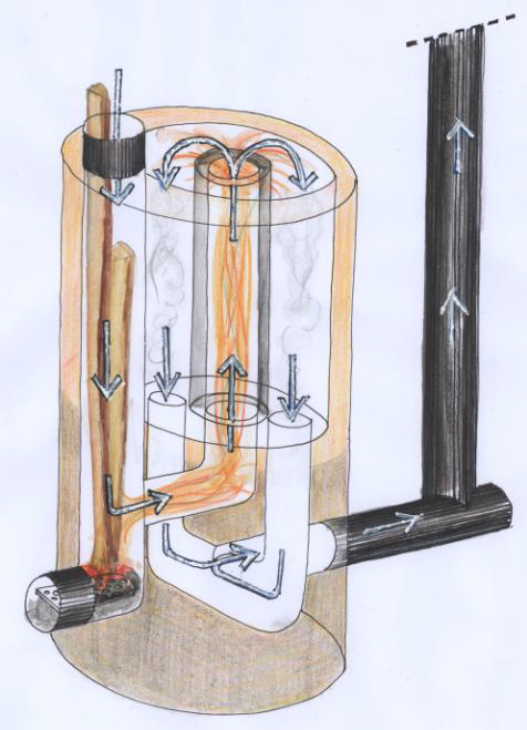
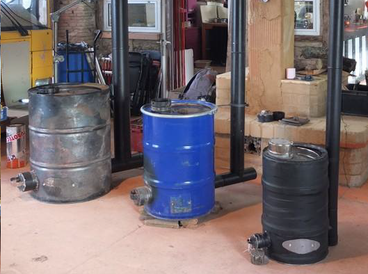
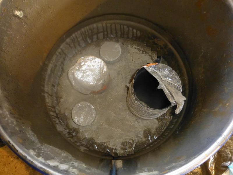
The idea behind the Poelito is to build a rocket stove inside a drum. The bottom of the drum is lined with an insulating mix of concrete; however the stove still needs to stand on a fire-proof support.The bottom part of the stove is cast in refractory concrete around a mould made of cardboard tubes. This is the area where the fire develops.Tubes are used to make the hollowed-out conduits: these are the routes which the smoke and fire take. The lower part forms the base of the fire pit and is a fixed body of material. The upper half is made up of removable metal pipes and is filled up with sand. This can either be left standing or transported separately. The fire pit can be closed to the outside either by a cast iron plate or by a pane of ceramic glass which can then be covered over by the drum lid as a finishing touch. The exhaust pipe is on the outside of the drum to which connection is made by a T joint with cap for cleaning out. Any pipes that go along the ceiling and to roof vents (or anything which goes outside of the dwelling) must be insulated.
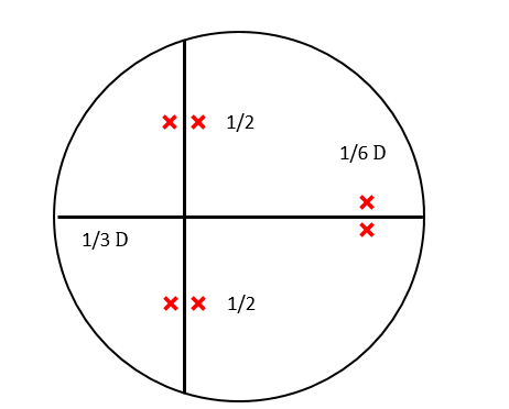
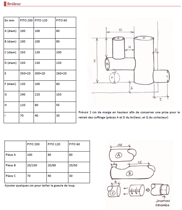
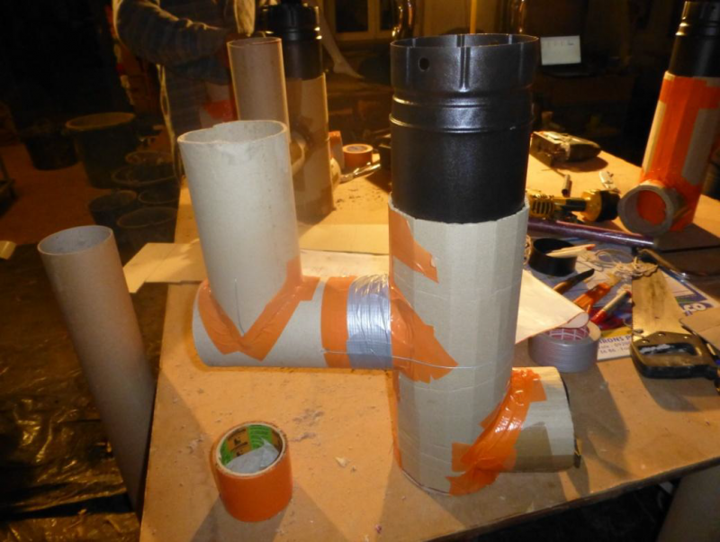
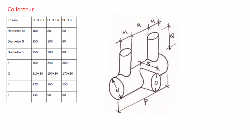
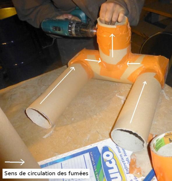
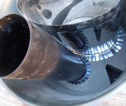
In the picture, you can see the bottom of the vertical feed pipe and the ash tray at the front and, behind, the pipe where the fire is lit . This together forms the burner. Towards the back, there are 2 pipes where the smoke is forced down. These are situated on either side of the pipe where the fire lit. These pipes join up underneath by means of a manifold which directs the smoke towards the back in the direction of the smoke exhaust which forms the manifold. Connection to the exhaust pipe is by means of a T with cap.
Étape 4 - Fundamental Health and Safety Rules
Étape 5 - Different types of Concrete: how to make them up and what goes in them.
Étape 6 - Preparing the drum
Étape 7 - Making the Ash Tray and Smoke Exhaust Holes
Étape 8 - Fitting the Ash Tubes and Smoke Exhaust
Étape 10 - Making the stopper for the ash tray
Étape 11 - Casting the protective bottom
Étape 13 - Positioning the Moulds.
Étape 15 - Removing the Moulds
Étape 16 - How to Make the Wood Feed Pipe.
Étape 17 - How to make the Wood Feed Stopper
Étape 18 - Making the Grate
Étape 23 - Painting
Étape 24 - Installation
Étape 25 - Filling it up with sand
Étape 26 - Fitting the glass
Étape 27 - Directions for use
Étape 28 - Maintenance
Published



 Français
 English
 Deutsch
 Español
 Italiano
 Português