(Page créée avec « "List of materials required for the generator, refer to the chapters for details" ») |
(Page créée avec « '''Watch [https://www.youtube.com/watch?v=e_sZ3tH_15E HERE] the video tutorial''' ») |
||
| (393 révisions intermédiaires par 2 utilisateurs non affichées) | |||
| Ligne 16 : | Ligne 16 : | ||
}} | }} | ||
{{Introduction | {{Introduction | ||
| − | |Introduction=''' | + | |Introduction='''Watch [https://www.youtube.com/watch?v=e_sZ3tH_15E HERE] the video tutorial''' |
This tutorial is based on the work of Scotsman Hugh Piggott [http://scoraigwind.co.uk/ Hugh Piggott]. It was directed with the help of Aurélie Guibert, a member of the Tripalium Network in Valence, France. | This tutorial is based on the work of Scotsman Hugh Piggott [http://scoraigwind.co.uk/ Hugh Piggott]. It was directed with the help of Aurélie Guibert, a member of the Tripalium Network in Valence, France. | ||
| − | It is about building a | + | It is about building a wind turbine of maximum power of 200W in 12V for a wingspan of 1m 20. It is designed for low power requirements such as lighting an LED or charging of a laptop. |
The distribution part of the electricity and the matting are not given in detail here. | The distribution part of the electricity and the matting are not given in detail here. | ||
| − | + | '''The Wind''' | |
| − | The power that the wind produces est proportional to the cube of its speed. For example, the | + | The power that the wind produces est proportional to the cube of its speed. For example, the wind turbine in this tutorial receives in its propeller 0.7W when the wind blows at 1m/s and a thousand times more at 10m/s. |
To calculate it: '''P= 1/2 x Rho x S x v^3''' with P: power (W), Rho: density of the air (about 1.23 kg/m 3), S: Surface swept by the propeller (m²), v: velocity of wind (m/s) | To calculate it: '''P= 1/2 x Rho x S x v^3''' with P: power (W), Rho: density of the air (about 1.23 kg/m 3), S: Surface swept by the propeller (m²), v: velocity of wind (m/s) | ||
| − | It is therefore necessary to study the land where we install the | + | It is therefore necessary to study the land where we install the wind turbine to see if the wind blows relatively constant and with sufficient speed for producing minimum energy. |
| − | Like every other system, a part of energy is lost by the | + | Like every other system, a part of energy is lost by the wind turbine. In theory, a wind turbine can never transform more than 60% of the energy that the wind provides, this is the Betz limit. In practice, with the type of wind turbine developed in this tutorial, the efficiency can reach up to 35%. |
| − | + | '''The location''' | |
| − | Generally, it is better to have land free from trees and dwellings. The | + | Generally, it is better to have land free from trees and dwellings. The wind turbines of the same height placed in cities or on the gables of the houses produce much less energy because of the wind's turbulence. Similarly, the wind is more constant and powerful on an altitude, therefore it is preferred to install a small wind turbine at height than a big wind turbine at a low altitude. |
| − | + | '''Cost''' | |
| − | Although it is a Low-tech, the cost of constructing this | + | Although it is a Low-tech, the cost of constructing this wind turbine is around 350€ if all the materials are bought. Including the matting and the electronics, the cost is around 2000€. It can be interesting to install it in off-grid areas with a view to autonomy. In the case of a network connection, it is not financially attractive. |
}} | }} | ||
{{TutoVideo | {{TutoVideo | ||
| Ligne 47 : | Ligne 47 : | ||
}} | }} | ||
{{Materials | {{Materials | ||
| − | |Material= | + | |Material='''List of materials required for the propeller, refer to the chapters for details''' |
| − | Scraps of plywood | + | * Scraps of plywood |
| − | Plank section minimum 95mm x 35mm, length 1m80. (red cedar or douglas or larch or spruce ) | + | * Plank section minimum 95mm x 35mm, length 1m80. (red cedar or douglas or larch or spruce ) |
| − | Plywood 9mm | + | *Plywood 9mm |
| − | Some screws of diameter 5mm, length 30mm. | + | * Some screws of diameter 5mm, length 30mm. |
| − | + | '''List of materials required for the generator, refer to the chapters for details''' | |
| − | * | + | * Metal disc of thickness 8mm and diameter 140mm. |
| − | * | + | * Rear wheel hub of golf, corsa, polo or Ibiza. |
| − | * 25cm | + | * 25cm of threaded rods with diameter 12mm. |
| − | * | + | * Pack of nuts of 12mm. |
| − | * | + | * 30cm threaded rods of diameter 10mm, 4 nuts of 10mm. |
| − | * | + | * Scraps of metal tube and angle. |
| − | * 4 | + | * 4 nails of diameter 6mm. |
| − | * 1 | + | * 1.5kg of enamelled copper wire, diameter 1.4mm. |
| − | * | + | * Electrical scotch. |
| − | * | + | * Heat-shrink tubes |
| − | * | + | * Plywood 9mm et 16mm. |
| − | * | + | * Glass fiber cloth (approximately 300g/m²) |
| − | * | + | * Polyester resin, associated catalyst |
* Talc. | * Talc. | ||
| − | * | + | * Mould release wax |
| − | * 8 | + | * 8 neodymium magnets. |
| − | * | + | * Steel disc of diameter 230mm, thickness 6mm. |
| − | * | + | * Bolts 12mm. |
| − | ''' | + | '''List of materials required for the steel structure, refer to the chapters for details''' |
| − | * | + | * Angle of 206mm (50x50x6mm). |
| − | * Tube | + | * Tube of outer diameter 42.2mm, length 100mm. |
| − | * Tube | + | * Tube of outer diameter 33.4mm, length 150mm. |
| − | * Tube | + | * Tube of outer diameter 42.2mm, length 130mm. |
| − | * | + | * Iron plate 50 x 50 x 6mm. |
| − | * Tube | + | * Tube of outer diameter 33.4mm, length 700mm. |
| − | * | + | * Angle 30 x 30 x 5, length 250mm. |
| − | * 60 cm | + | * 60 cm of threaded rods with diameter 12mm. |
| − | |Tools=''' | + | |Tools='''List indicative of equipment, refer to the chapters for details''' |
| − | * | + | * Saws (hand, jigsaw, circular). |
| − | * | + | * Pencils, markers. |
| − | * | + | * Measuring tape, ruler, try-square, compass. |
| − | * | + | * Clamps |
| − | * | + | * Palm plane, wood chisels, spokeshave, hand planes. |
| − | * | + | * Drill, screwdriver, metal and wood drill up to 14mm, a Hole Cutter of diameter 60mm. |
| − | * | + | * Grinding machine, cutting blades, grinding discs, gloves and safety glasses. |
| − | * | + | * Welding station. |
| − | * | + | * Soldering iron, tin. |
| − | * | + | * electronic scale. |
| − | * | + | * graduated syringes. |
| − | * | + | * Latex gloves. |
| − | * | + | * Plastic trays, |
| − | * | + | * Pair of scissors. |
| − | * | + | * Voltmeter |
|Tuto_Attachments={{Tuto Attachments | |Tuto_Attachments={{Tuto Attachments | ||
|Attachment=Eolienne_200W_Affiche_EoliennePigott_FR.pdf | |Attachment=Eolienne_200W_Affiche_EoliennePigott_FR.pdf | ||
| Ligne 148 : | Ligne 148 : | ||
}} | }} | ||
{{Tuto Step | {{Tuto Step | ||
| − | |Step_Title= | + | |Step_Title=Propeller: The pattern |
| − | |Step_Content=* | + | |Step_Content=* Draw and cut the blade pattern in a board. |
| − | * | + | * Note on each side of the pattern, the one which corresponds the '''lower surface''' and the one which corresponds the '''upper surface'''. |
| − | ''' | + | ''' Note ''': The '''lower surface''' is the side of the blade which receives the wind, the '''upper surface''' is the back side of the blade. |
|Step_Picture_00=Eolienne_200W_patron_2.jpg | |Step_Picture_00=Eolienne_200W_patron_2.jpg | ||
|Step_Picture_01=Eolienne_200W_2017.08.28_-_19.JPG | |Step_Picture_01=Eolienne_200W_2017.08.28_-_19.JPG | ||
}} | }} | ||
{{Tuto Step | {{Tuto Step | ||
| − | |Step_Title= | + | |Step_Title=Propeller: drawing and cutting of the blades. |
| − | |Step_Content=* | + | |Step_Content=* Choose a plank of dimension minimum 95mm x 35mm |
| − | ''' | + | '''Notes''': |
| − | 1) | + | 1) The wood should be imputrescible, light-weighted and easy to work with. For example, red cedar, Oregon pine, spruce, larch, douglas fir may be suitable. |
2) For this tutorial, the section of the red cedar plank is 150mm x 45mm. | 2) For this tutorial, the section of the red cedar plank is 150mm x 45mm. | ||
| − | 3) | + | 3) The parameter which determines the energy transmitted by the wind at the propeller is the length of the blade and not it’s breadth. |
| − | * | + | *With the help of the blade pattern, '''lower side visible''', mark the location for the first blade. |
| − | ''' | + | '''Notes''': |
| − | 1) | + | 1) Put the knots and defects of the wood at the end of the blade, so that the thinnest part does not become fragile (middle-end of the blade). |
| − | 2) | + | 2) Select the leading edge ridge as neatly as possible. This ridge will not be altered during the cutting of the blade. |
| − | 3) | + | 3) Extend the blade tip pattern by 4-5 cm to maintain a margin in case of damage. |
| − | * | + | * Do the same for the 2 other blades and cut the blades. |
| − | ''' | + | '''Note''': When using a circular saw for cutting, be careful to place the width of the blade always on the outside of the line. |
| − | * | + | * Rectify the left of the blades if necessary with the help of a plane. |
| − | * | + | * Fix the 3 blades together with the help of the clamps and equalize all the irregular planes. All the 3 blades needs to be strictly identical. |
| − | * | + | * Mark the position of the leading edge ridge for it to stay where it is. It will be its landmark. |
|Step_Picture_00=Eolienne_200W_2017.08.28_-_67.JPG | |Step_Picture_00=Eolienne_200W_2017.08.28_-_67.JPG | ||
|Step_Picture_01=Eolienne_200W_2017.08.28_-_24.JPG | |Step_Picture_01=Eolienne_200W_2017.08.28_-_24.JPG | ||
| Ligne 196 : | Ligne 196 : | ||
}} | }} | ||
{{Tuto Step | {{Tuto Step | ||
| − | |Step_Title= | + | |Step_Title=Propeller: Sculpture of the lower surface of the blades |
| − | |Step_Content=* | + | |Step_Content=* According to the diagram, draw the 4 sections along the blade. |
| − | * | + | * According to the diagram, draw the area of the inner surface to be sculpted. |
| − | * | + | * For easy reference, hatch/shade the area of the wood to be eliminated. |
| − | * | + | * With the help of a plane, chisels, and a spokeshave for the finishing, cut off the hatched/shaded part of the wood. |
| − | ''' | + | '''Note''': To guarantee good dimensions, the sculpture must come as close as possible to the pencil stroke without erasing it. |
| − | * | + | * With the help of a scale, check the evenness of all sections of the sculpted lower surface of the blade. |
| − | * | + | * Once the 3 blades are finished, check if all the dimensions are equal on multiple points on the 4 sections drawn previously. |
|Step_Picture_00=Eolienne_200W_pale_1_style.jpg | |Step_Picture_00=Eolienne_200W_pale_1_style.jpg | ||
|Step_Picture_01=Eolienne_200W_pale_2_style.jpg | |Step_Picture_01=Eolienne_200W_pale_2_style.jpg | ||
| Ligne 218 : | Ligne 218 : | ||
}} | }} | ||
{{Tuto Step | {{Tuto Step | ||
| − | |Step_Title= | + | |Step_Title=Propeller: Sculpture of the lower surface of the blades |
| − | |Step_Content=* | + | |Step_Content=* Position the blade in such a way that it's '''upper surface''' is visible. |
| − | * | + | * According to the diagram, draw the point '''A'''. It is on 2/3 of the width of the blade's base from the trailing edge. This point is the center of rotation of the propeller. |
| − | * | + | * Then draw the point '''B''' on the leading edge by using a compass centered in '''A''' the 2/3 of the blade base. Then join '''AB'''. |
| − | ''' | + | '''Note''': The segment '''AB''' form an angle of 120° with the base of the blade, which will be later required for the assembly of the blades. |
| − | * | + | * According to the diagram, draw a circle of radius 100mm centered at A. The surface of this portion of the disc should be left intact and levelled until the end for proper blade assembly. |
| − | ''' | + | '''Note''': In the case of this tutorial, the point '''B''' is situated on the perimeter of the circle. This is not always the case depending on the width of the plank. |
| − | * | + | * According to the diagram, draw the thickness of the blade on the irregular planes. |
| − | ''' | + | '''Note''': According to the thickness of the plank, it might appear that the thickness is not 17mm in section 3. Imagine a point in the space for the thickness 17mm on the rear edge on this section 3. |
| − | * | + | * Name '''C''' to the intersection between the point traced for the thickness and the base of the blade. |
| − | * | + | * According to the diagram, then draw the thickness of the blade at the front edge respecting the same thickness as that of the irregular plane. Connect the point of the section 3 to the point '''B'''. |
| − | * | + | * On the upper surface side, connect '''B''' and '''C''' to close the area to be sculpted. |
| − | * | + | * For easy reference, hatch/shade the area of the wood to be eliminated. |
| − | * | + | * With the help of a plane, chisels, and a spokeshave for the finishing, cut off the hatched/shaded part of the wood. |
| − | ''' | + | '''Note''': To guarantee good dimensions, the sculpture must come as close as possible to the pencil stroke without erasing it. |
| − | * | + | * With the help of a scale, check the evenness of all sections of the sculpted lower surface of the blade. |
| − | * | + | * Once the 3 blades are finished, check if all the dimensions are equal on multiple points on the 4 sections drawn previously. |
|Step_Picture_00=Eolienne_200W_pale_5_style_m.jpg | |Step_Picture_00=Eolienne_200W_pale_5_style_m.jpg | ||
|Step_Picture_01=Eolienne_200W_pale_6_style.jpg | |Step_Picture_01=Eolienne_200W_pale_6_style.jpg | ||
| Ligne 258 : | Ligne 258 : | ||
}} | }} | ||
{{Tuto Step | {{Tuto Step | ||
| − | |Step_Title= | + | |Step_Title=Propeller: Blade profile finalization |
| − | |Step_Content=* | + | |Step_Content=* On the '''upper surface''', draw a line representing 30% of the width of the blade and a line representing 50% of the width of the blade from the leading edge. |
| − | * | + | * Check, with the help of the caliper compass, the thickness of each section on the line of 30%. Compare the 3 blades and adjust the thicker ones if they are not exactly identical. |
| − | ''' | + | '''Note''': The 30% line corresponds to the final thickness of the blade, which is why we check the dimensions at this precise location. |
| − | * | + | * From the 50% line to the rear edge, sculpt a flat surface leaving a thickness of less than 1 mm on the rear edge. |
| − | ''' | + | '''Note''': Be careful not to crack the rear edge as it is very delicate area. |
| − | * | + | * From the leading edge to the 30% line, sculpt a beautiful rounding using a hand plane, spokeshaven or palm plane. The angle of the leading edge should be approximately 60°. |
| − | * | + | * When these two areas are complete, break the remaining 50% line block to achieve a continuous profile from leading edge to trailing edge. The only line still visible in pencil should be the 30% line. |
| − | + | Once the work on the 3 blades is completed: | |
| − | * | + | * Saw the blades at 600mm to remove the margin left at the beginning of the blade tip with a Japanese saw. |
| − | * | + | * Saw the section marked as '''AB''' on the base of the blade to the interlock the 3 blades at 120°. |
| − | ''' | + | '''Note''': The angle should be slightly less than 120° in order to be able to rotate the blades slightly during assembly. |
|Step_Picture_00=Eolienne_200W_2017.08.30_-_42.JPG | |Step_Picture_00=Eolienne_200W_2017.08.30_-_42.JPG | ||
|Step_Picture_01=Eolienne_200W_pale_11_style.jpg | |Step_Picture_01=Eolienne_200W_pale_11_style.jpg | ||
| Ligne 287 : | Ligne 287 : | ||
}} | }} | ||
{{Tuto Step | {{Tuto Step | ||
| − | |Step_Title= | + | |Step_Title=Propeller: Construction of assembly supports |
| − | |Step_Content=* | + | |Step_Content=* According to the diagram, make a disc and its tracks/holes in a plywood of thickness 9mm. The diameter of the circles for the positioning of the pre-drilling of the screws (for 5mm screws) is fixed arbitrarily. 3 zones at 120° are defined. This disc is used to assemble the propeller on the outer side. |
| − | * | + | * According to the diagram, make a triangle and its tracks/holes in a plywood of thickness 9mm. Each blade's base, on the outer surface of the triangle, is represented on the triangle. The outline of the central circle does not allow the pre-drilled to enter this area which will subsequently accommodate threaded rods. The lines parallel to the sides for pre-drills (for 5mm screws) are randomly defined. This triangle is used to assemble the propeller on the inner surface. |
|Step_Picture_00=Eolienne_200W_disque_cp_1_style_m.jpg | |Step_Picture_00=Eolienne_200W_disque_cp_1_style_m.jpg | ||
|Step_Picture_01=Eolienne_200W_triangle_cp_1_style_m.jpg | |Step_Picture_01=Eolienne_200W_triangle_cp_1_style_m.jpg | ||
| Ligne 297 : | Ligne 297 : | ||
}} | }} | ||
{{Tuto Step | {{Tuto Step | ||
| − | |Step_Title= | + | |Step_Title=Propeller: Assembly |
| − | |Step_Content=* | + | |Step_Content=* Place the blade on the propeller on a good flat surface with the outer surface side visible. |
| − | * | + | * Place the disc in the center of the plywood, with the help of a drill with a centering pin. |
| − | * | + | * With 3 measuring tape and 3 people, position the circle in such a way that the tip of the blade should be equidistant from the centering pin. The tip of the blade here means the tip of the leading edge. |
| − | * | + | * Once it is placed correctly in the center, maintain the circle's position and screw-in '''one screw for each blade''' so that it can still pivot. |
| − | * | + | * Then adjust the distance between every tip of the blade with a measuring tape. |
| − | * | + | * Hold the position and then screw-in all the screws. |
| − | * | + | * Screw-in the triangle on the side intrados while taking care to place the right side of the triangle so that the pre-drills are in front of the blade foot. |
| − | * | + | * Expand the 4 holes of 12mm on the plywood disc along the entire propeller. Use a square to ensure vertical holes. |
| − | ''' | + | '''Note''': To help the propeller to fit-in on the rest of the wind turbine, it is possible to enlarge the holes of 12mm in 14mm on the thickness of the triangle and the blades, '''without touching the diameter 12mm of the disc'''. |
| − | * | + | * With an hole cutter of 60mm diameter, cut a cylinder of 30mm deep from the side extrados. |
|Step_Picture_00=Eolienne_200W_2017.09.01_-_52.JPG | |Step_Picture_00=Eolienne_200W_2017.09.01_-_52.JPG | ||
|Step_Picture_01=Eolienne_200W_2017.09.01_-_55.JPG | |Step_Picture_01=Eolienne_200W_2017.09.01_-_55.JPG | ||
| Ligne 325 : | Ligne 325 : | ||
}} | }} | ||
{{Tuto Step | {{Tuto Step | ||
| − | |Step_Title= | + | |Step_Title=Generator, stator: Preparation of the cradle. |
| − | |Step_Content=* | + | |Step_Content=* Take a metallic disc of diameter 140mm and thickness 8mm. |
| − | * | + | * According to the diagram, drill holes at 12mm. |
| − | ''' | + | '''Note''': For a precise hole, point the center with a pin, pre-drill with a drill of small diameter and then at 12mm. Choose a [http://www.usinages.com/threads/vitesse-de-rotation-pour-percage.4390/ rotation speed adapted to] material and diameter of drill. Lubricate well during drilling. |
| − | * | + | * Take a rear wheel hub of Golf, Corsa, Polo or Ibiza, it can be recovered from a scrapped car. Separate the part that attaches to the car (spindle) and the rotating part (a bell-shaped part) while careful putting aside the nuts and ball bearings. |
| − | * | + | * Draw a circle of radius slightly greater than 40mm on the metallic disc to center the spindle's base on the cradle. |
| − | + | Fix the two part temporarily with a few soldering points. Make the 4 drills across the base of the spindle and the cradle. | |
| − | ''' | + | '''Note''': If the 4 initial screws of the spindle are in good condition, they can be recovered by drilling only the cradle and screwing directly into the base. In this case, care should be taken that the original threading should not get damaged (which is a mechanical threading and cannot be used with other screws). It is sometimes necessary to shorten these screws so as to avoid problems during assembly. |
| − | * | + | *Drill the center of the cradle with a small drill (approx 3mm). This drilling will be used when the stator is cast. |
|Step_Picture_00=Eolienne_200W_berceau_1_style.jpg | |Step_Picture_00=Eolienne_200W_berceau_1_style.jpg | ||
|Step_Picture_01=Eolienne_200W_2017.08.30_-_109m.JPG | |Step_Picture_01=Eolienne_200W_2017.08.30_-_109m.JPG | ||
| Ligne 345 : | Ligne 345 : | ||
}} | }} | ||
{{Tuto Step | {{Tuto Step | ||
| − | |Step_Title= | + | |Step_Title=Generator, stator: Preparation threaded stator rods |
| − | |Step_Content=''' | + | |Step_Content='''Note''': The '''stator''' is the fixed part of the generator. |
| − | * | + | * Take a threaded rod of 12mm diameter. |
| − | * | + | * Cut 3 70mm long rods. |
| − | ''' | + | '''Notes''': |
| − | 1) | + | 1) If a clamp is used to maintain the threaded rod while cutting, wrap the threaded rod in a cloth at the jaws before tightening, to avoid damage to the screw pitch. |
| − | 2) | + | 2) Before cutting the rod, screw a nut on the part of the rod that will be cut in order to reform the pitch of the screw at the level where it is been cut through the repeating passage of the nut. |
| − | * | + | * Make slits to form cross of 10mm deep on one end of each threaded rod. |
| − | * | + | * Set aside the cradle and the 3 threaded rods, they will be useful during the molding later. |
|Step_Picture_00=Eolienne_200W_2017.08.31_-_22.JPG | |Step_Picture_00=Eolienne_200W_2017.08.31_-_22.JPG | ||
|Step_Picture_01=Eolienne_200W_2017.08.31_-_29.JPG | |Step_Picture_01=Eolienne_200W_2017.08.31_-_29.JPG | ||
}} | }} | ||
{{Tuto Step | {{Tuto Step | ||
| − | |Step_Title= | + | |Step_Title=Generator, stator: Preparation of the coil. |
| − | |Step_Content=* | + | |Step_Content=* Make the coil with the help of the angle, metallic tube, threaded rod/nuts of 10mm diameter, 4 large nails of diameter of 6 and plywood scraps. Follow the dimensions from the diagram while cutting the plywood: the rectangle defined by the 4 large nails on the outer edges should be of dimensions 46mm x 30mm. |
| − | ''' | + | '''Notes''': The coils will be wound between the 2 discs of the plywood (thickness minimum 15mm), which are known as "ears". The small plywood rectangle between the two ears is the spacer: which determines the thickness of the coil. The inner shape of the coil is determined by the outer edges of the 4 large nails, this forms a rectangle of 46mm x 30mm. This rectangle corresponds to the dimensions of the magnets that will pass in front. |
| − | * | + | * After completing the metal “base” structure of the coiler, cut out both ears and the spacer as shown. Make with drills with precision. Cut a small notch on one of the two ears to catch the copper wire while winding it. |
| − | ''' | + | '''Notes''': For the easy slippage of the wire, you can bevel the inner edges of the ears. Make markings with a marker on the edge of both ears to count the turns more easily. |
|Step_Picture_00=Eolienne_200W_2017.08.28_-_200.JPG | |Step_Picture_00=Eolienne_200W_2017.08.28_-_200.JPG | ||
|Step_Picture_01=Eolienne_200W_2017.08.28_-_201.JPG | |Step_Picture_01=Eolienne_200W_2017.08.28_-_201.JPG | ||
| Ligne 378 : | Ligne 378 : | ||
}} | }} | ||
{{Tuto Step | {{Tuto Step | ||
| − | |Step_Title= | + | |Step_Title=Generator, stator: Making of 6 coils. |
| − | |Step_Content=''' | + | |Step_Content='''Notes''': The stator is composed of 6 coils made with 76 rounds of 1.4mm diameter enameled copper wire. This allows the generator to produce maximum 200W in 12V without damaging the wires. In order to make 6 coils, 1.5kg of copper wire is required. |
| − | * | + | * With the help of one person and a coiler, windup a coil. 1 person can wind up the wire and count the turns precisely, one person can create tension in the wire and assure correct distribution of wire over the thickness of the coiler. If the wire does not have enough tension, the coil will be too wide. |
| − | * | + | * Leave a margin of 60cm of the wire before starting to coil the wire and the end as well. |
| − | * | + | * Before unmolding, seal the coil with an electrical tape. A ruler can be use to pass the tape between the spacer and the coil, with the help of the large slots on the ears which were created for this purpose. |
| − | * | + | * Make 6 coils in total. |
|Step_Picture_00=Eolienne_200W_2017.08.28_-_220.JPG | |Step_Picture_00=Eolienne_200W_2017.08.28_-_220.JPG | ||
|Step_Picture_01=Eolienne_200W_2017.08.28_-_231.JPG | |Step_Picture_01=Eolienne_200W_2017.08.28_-_231.JPG | ||
| Ligne 394 : | Ligne 394 : | ||
}} | }} | ||
{{Tuto Step | {{Tuto Step | ||
| − | |Step_Title= | + | |Step_Title=Generator, stator: "Star" mounting |
| − | |Step_Content=* | + | |Step_Content=* Make the template from the diagram on the scrap plywood. Mark the position for the 3 threaded rods at the center and also mark for the centers of the coils. There are 6 coils, the gap between each is 60°. |
| − | * | + | * With the help of 6 plywood scraps of approximate 50mm x 25mm, attach each coil to its position on the template. Number each coil from 1 to 6 as shown in the template. |
| − | ''' | + | '''Notes''': It is '''important''' that all coils are positioned with '''the coils turning in the same direction''', either clockwise or anti-clockwise. If this instruction is not respected, the generator will not function as expected. |
| − | * | + | * Link the coils according to the diagram while taking care of letting the center and the placement of the threaded rods free. |
| − | + | * Connect the inputs of the coils 1,2 et 3: this is the neutral point. | |
| − | 2) | + | 2) Connect the output of 1 to the input of 4. |
| − | 3) | + | 3) Connect the output of 2 to the input of 5. |
| − | 4) | + | 4) Connect the output of 3 to the input of 6. |
| − | * | + | * Cut the extra wire from each coil. |
| − | * | + | * With the help of the cutter, remove the enamel up to 3cm on every wire. The surface of the wire should be clearer and more matte. |
| − | * | + | * Twist the wires of each connection. |
| − | * | + | * Solder the connections with a soldering iron. For a good solder, heat the area to be soldered then put the tin on the wire so that it melts and fills the gaps. |
| − | * | + | * Protect each weld with heat shrink tube. |
|Step_Picture_00=Eolienne_200W_gabarit_bobine_1_style.jpg | |Step_Picture_00=Eolienne_200W_gabarit_bobine_1_style.jpg | ||
|Step_Picture_01=Eolienne_200W_2017.08.29_-_98.JPG | |Step_Picture_01=Eolienne_200W_2017.08.29_-_98.JPG | ||
| Ligne 428 : | Ligne 428 : | ||
}} | }} | ||
{{Tuto Step | {{Tuto Step | ||
| − | |Step_Title= | + | |Step_Title=Generator, stator: Three-phase cable |
| − | |Step_Content=* | + | |Step_Content=* Take 60cm of flexible 3-wire cable, 2.5mm². |
| − | * | + | * Solder de the ends of the coil 4,5, and 6 forming the 3 phases then protect them with the heat shrinking sleeves. Special attention need to paid to the insulation, the wires can touch each other. |
|Step_Picture_00=Eolienne_200W_2017.08.29_-_137_m.JPG | |Step_Picture_00=Eolienne_200W_2017.08.29_-_137_m.JPG | ||
}} | }} | ||
{{Tuto Step | {{Tuto Step | ||
| − | |Step_Title= | + | |Step_Title=Generator, stator: Making the stator mould |
| − | |Step_Content=* | + | |Step_Content=* In 10 mm thick plywood, make the mold according to the diagram. It is divided into 4 parts: the base, the border, the central isle and the lid. Make sure to drill in 3 detractors for the correct alignment of the cover to the molding. |
| − | |||
| − | * | + | * Screw/glue the border and central isle to the base. |
| − | * | + | * Mark the location of every coil in the mould. The previously made template can be used. |
|Step_Picture_00=Eolienne_200W_moule_stator_eclat_.jpg | |Step_Picture_00=Eolienne_200W_moule_stator_eclat_.jpg | ||
|Step_Picture_01=Eolienne_200W_moule_stator_emboit_.jpg | |Step_Picture_01=Eolienne_200W_moule_stator_emboit_.jpg | ||
| Ligne 447 : | Ligne 446 : | ||
}} | }} | ||
{{Tuto Step | {{Tuto Step | ||
| − | |Step_Title= | + | |Step_Title=Generator, stator: Preparation of the molding. |
| − | |Step_Content=''' | + | |Step_Content='''Notes''': This step includes use of dangerous elements (resin, fibers, etc. ) Make sure to put on the latex gloves and safety glasses till the end of the molding. |
| − | * | + | * Prepare 2 disks of glass fiber of the shape of the mold and keep them aside. Provide a diameter margin at the isle level. (See photo) |
| − | * | + | * Prepare the 3 threaded rods by screwing them on the cradle. Adjust the parallelism of the rod well. |
| − | * | + | * With the help of the wax, wax the entire mold, interior/exterior, the interior/exterior of the cover, all the screws which keeps the cover fixed and the 3 pawns of the detractor. |
| − | * | + | * Prepare 2 container of 150g of polyester resin and 2 syringes of 2.25ml of the catalyst. |
| − | * | + | * Prepare a container of 300g of mixed resin with 150g of talc also a syringe of 4.5ml of catalyst. |
| − | * | + | * Prepare the complete mounting of the coil, unbridled from the template, so that it will ready to be installed in the mold. |
|Step_Picture_00=Eolienne_200W_2017.08.31_-_43.JPG | |Step_Picture_00=Eolienne_200W_2017.08.31_-_43.JPG | ||
|Step_Picture_01=Eolienne_200W_2017.08.31_-_91.JPG | |Step_Picture_01=Eolienne_200W_2017.08.31_-_91.JPG | ||
| Ligne 468 : | Ligne 467 : | ||
}} | }} | ||
{{Tuto Step | {{Tuto Step | ||
| − | |Step_Title= | + | |Step_Title=Generator, stator: Molding. |
| − | |Step_Content=* | + | |Step_Content=* Pour the associated syringe into the 300g resin container + talc. Mix vigorously. |
| − | * | + | * Pour some of this resin into the bottom of the mold. |
| − | * | + | * Put one of the two glass fiber discs to the bottom of the mold and soak well with resin. |
| − | * | + | * Place the mounting of the coil in the mold carefully. Every coil must be placed correctly in its place and no wire should come out of the mold. '''It's a delicate step'''. Pour the first container of resin completely. |
| − | * | + | * Pour the associated syringe into the 300g resin container + talc. Mix vigorously. |
| − | * | + | * Pour the content on the assembly. |
| − | ''' | + | '''Notes''': the talc not only charges the resin using a cheaper material but also diffuses the heat during the drying of the resin and also during the future operation of the wind turbine without damaging the stator. |
| − | * | + | * Position the second disk of glass fiber and soak it well. |
| − | * | + | * Prepare and pour the last container of resin. It is better to have extra resin. |
| − | * | + | * Position the cover with the help of the detractors and secure them with the waxed screws. |
| − | * | + | * Position the threaded rods attached to the cradle delicately, the part split in the resin. Use the drill bit as the center piece between the isle and the cradle. |
| − | * | + | * If necessary, use a clamp to secure the three-phase cable so that it exits the stator correctly. |
| − | + | Allow to harden (it might take several hours). Then demold, deburr and varnish or paint. | |
|Step_Picture_00=Eolienne_200W_2017.08.31_-_132.JPG | |Step_Picture_00=Eolienne_200W_2017.08.31_-_132.JPG | ||
|Step_Picture_01=Eolienne_200W_2017.08.31_-_134.JPG | |Step_Picture_01=Eolienne_200W_2017.08.31_-_134.JPG | ||
| Ligne 502 : | Ligne 501 : | ||
}} | }} | ||
{{Tuto Step | {{Tuto Step | ||
| − | |Step_Title= | + | |Step_Title=Generator, rotor: Preparation of the metallic disk. |
| − | |Step_Content=''' | + | |Step_Content='''Note''': The '''rotor''' is the rotating part of the generator triggered by the propeller. |
| − | * | + | * Use a 6mm thick steel disk, if possible galvanized, of diameter 230mm and prepare it according to the diagram. The 4 holes of 12mm diameter are distributed on each quarter of the circle of 100mm diameter. |
| − | ''' | + | '''Notes''': |
| − | 1) | + | 1) It is '''important''' that the disk is made of '''steel''' so that it can conduct the magnetic fields. It will not work with aluminum or stainless steel. |
| − | 2) Il | + | 2) Il can be easier to get the disk prepared from craftsmen who have precise cutting tools (plasma, laser) |
|Step_Picture_00=Eolienne_200W_disque_galva_style.jpg | |Step_Picture_00=Eolienne_200W_disque_galva_style.jpg | ||
|Step_Picture_01=Eolienne_200W_2017.08.29_-_173.JPG | |Step_Picture_01=Eolienne_200W_2017.08.29_-_173.JPG | ||
}} | }} | ||
{{Tuto Step | {{Tuto Step | ||
| − | |Step_Title= | + | |Step_Title=Generator, rotor: Preparation of the bell hub. |
| − | |Step_Content=* | + | |Step_Content=* Use the bell hub which was previously kept aside. ( See step: Generator, stator: Preparation of the cradle) |
| − | * | + | * Cut the bell with a grinding machine, so that only the flat plate with the holes remains. |
| − | * | + | * Cut the bell in a way that the steel disk fits perfectly flat on the 4 drilled supports. |
|Step_Picture_00=Eolienne_200W_2017.08.31_-_61.JPG | |Step_Picture_00=Eolienne_200W_2017.08.31_-_61.JPG | ||
|Step_Picture_01=Eolienne_200W_2017.08.31_-_65.JPG | |Step_Picture_01=Eolienne_200W_2017.08.31_-_65.JPG | ||
| Ligne 528 : | Ligne 527 : | ||
}} | }} | ||
{{Tuto Step | {{Tuto Step | ||
| − | |Step_Title= | + | |Step_Title=Generator, rotor: Preparation of the template. |
| − | |Step_Content=* | + | |Step_Content=* On a piece of thin plywood, make the template according to the diagram |
| − | * | + | * Degrease the steel disk using a degreaser. |
| − | * | + | * Take two bolts of 12mm with washers. |
| − | * | + | * Screw the template onto the steel disk by inserting the washers. |
|Step_Picture_00=Eolienne_200W_gabarit_rotor.jpg | |Step_Picture_00=Eolienne_200W_gabarit_rotor.jpg | ||
|Step_Picture_01=Eolienne_200W_2017.08.29_-_177.JPG | |Step_Picture_01=Eolienne_200W_2017.08.29_-_177.JPG | ||
}} | }} | ||
{{Tuto Step | {{Tuto Step | ||
| − | |Step_Title= | + | |Step_Title=Generator, rotor: Gluing of magnets |
| − | |Step_Content=''' | + | |Step_Content='''Note''': This step consists of gluing together strong magnets on the steel disk by '''alternating the poles of the magnets'''. If the alternation is not respected, the generator will not function and there is risk of damage. |
| − | * | + | * Have the [https://www.supermagnete.fr/aimants-bloc-neodyme/parallelepipede-magnetique-46mm-x-30mm-x-10mm-neodyme-n40-nickele_Q-46-30-10-N 8 neodymium magnet] 46mm x 30mm x 10mm. |
| − | ''' | + | '''Note''': Be very carefully during the manipulation of these magnets. Being very powerful, they can damage electronic devices, attract all kinds of metal objects and squeeze them very hard. |
| − | * | + | * Apply a dot of super glue on the first notch and stick the first magnet. Make sure that the magnet is perfectly locked in the notch. |
| − | * | + | * Take the second magnet in your hand and place it on top of the first. |
| − | 1) | + | 1) If there is repulsion, stick it in the adjacent notch keeping this direction: the 2 magnets have the polarities positioned in an opposite way. |
| − | 2) | + | 2) If there is attraction, turn it over in your hand, check if there is repulsion now and then stick it in the adjacent notch. |
| − | * | + | * Apply the same procedure with all the magnets. Once finished, the faces visible of the magnets will be alternate as follows: 1) North, 2)South,3)North, 4)South 5)North, 8)South or inverse. |
| − | * | + | * Let it dry then remove the template. |
|Step_Picture_00=Eolienne_200W_2017.08.29_-_178.JPG | |Step_Picture_00=Eolienne_200W_2017.08.29_-_178.JPG | ||
|Step_Picture_01=Eolienne_200W_2017.08.29_-_199.JPG | |Step_Picture_01=Eolienne_200W_2017.08.29_-_199.JPG | ||
}} | }} | ||
{{Tuto Step | {{Tuto Step | ||
| − | |Step_Title= | + | |Step_Title=Generator, rotor: Preparation of the mold. |
| − | |Step_Content=* | + | |Step_Content=* Make a rotor mold out of a 16mm thick plywood for the base and the border, the cover can be thinner. The diameter of the holes in the cover should allow the passage of the nut for the 12mm screws. |
| − | * | + | * Screw/glue the base and the border together. |
|Step_Picture_00=Eolienne_200W_moule_rotor.jpg | |Step_Picture_00=Eolienne_200W_moule_rotor.jpg | ||
|Step_Picture_01=Eolienne_200W_moule_rotor_ensemble.jpg | |Step_Picture_01=Eolienne_200W_moule_rotor_ensemble.jpg | ||
| Ligne 571 : | Ligne 570 : | ||
}} | }} | ||
{{Tuto Step | {{Tuto Step | ||
| − | |Step_Title= | + | |Step_Title=Generator, rotor: Preparation of the molding. |
| − | |Step_Content=''' | + | |Step_Content='''Notes''': This step includes use of dangerous elements (resin, fibers, etc. ) Make sure to put on the latex gloves and safety glasses till the end of the molding. |
| − | * | + | * Prepare 1 disk of glass fiber of the shape of the mold then keep it aside. |
| − | * | + | * Using mold release wax/wax, wax the entire mold, inside/outside, the internal/external cover and also the two 12mm bolts which are long enough to pass through the mold completely. |
| − | + | Prepare two 150g container of polyester resin and two 2.25ml syringes of the associated catalyst. | |
| − | * | + | * Prepare a container of 300g of mixed resin with 150g of talc also a syringe of 4.5ml of catalyst. |
| − | * | + | * Position the steel disk in the mold, place the isle on the top and screw the assembly with the greased bolts. |
|Step_Picture_00=Eolienne_200W_2017.08.31_-_57.JPG | |Step_Picture_00=Eolienne_200W_2017.08.31_-_57.JPG | ||
|Step_Picture_01=Eolienne_200W_2017.08.31_-_103.JPG | |Step_Picture_01=Eolienne_200W_2017.08.31_-_103.JPG | ||
| Ligne 588 : | Ligne 587 : | ||
}} | }} | ||
{{Tuto Step | {{Tuto Step | ||
| − | |Step_Title= | + | |Step_Title=Generator, rotor: Molding. |
| − | |Step_Content=* | + | |Step_Content=* Pour the associated syringe into the 150g resin container et mix vigorously. |
| − | * | + | * Pour this resin in the mold. |
| − | * | + | * In the same way, prepare and pour the resin + talc. |
| − | * | + | * Position the fiber circle and let it soak properly. |
| − | * | + | * Prepare and pour the last container of resin. It is better to have extra resin that overflows. |
| − | * | + | * Position the cover and put heavy metal parts on it (angles, tubes, etc.) the attraction force of the magnets will press the excess resin. |
| − | * | + | * Let it harden, then demold, deburr and varnish or paint. |
|Step_Picture_00=Eolienne_200W_2017.08.31_-_147.JPG | |Step_Picture_00=Eolienne_200W_2017.08.31_-_147.JPG | ||
|Step_Picture_01=Eolienne_200W_2017.08.31_-_153.JPG | |Step_Picture_01=Eolienne_200W_2017.08.31_-_153.JPG | ||
| Ligne 609 : | Ligne 608 : | ||
{{Tuto Step | {{Tuto Step | ||
|Step_Title=Structure, Nacelle | |Step_Title=Structure, Nacelle | ||
| − | |Step_Content=* | + | |Step_Content=* Equip yourself with: |
| − | + | * An angle of 206mm (50x50x6mm). | |
| − | 2) | + | 2) A tube of external diameter of 42.2, length 100mm: '''Pivot wind turbine'''. |
| − | 3) | + | 3) A tube of external diameter of 33.4mm, length 150mm: '''Rudder Pivot'''. |
| − | 4) | + | 4) The '''cradle''' previously made. |
| − | * | + | * Prepare the angle according to the diagram. |
| − | * | + | * Solder the wind turbine pivot tube under the angle, centered with the 14mm hole and perpendicular to the angle. |
| − | * | + | * Solder the rudder pivot tube at the back of the angle (See photo) |
| − | * | + | * Solder the cradle at the end of the angle by centering the center of the cradle on the point A. For the soldering, it is necessary to sacrifice one of the four holes allowing the fixation of the spindle. It is not a problem though since all the other holes are very well accessible. |
| − | ''' | + | '''Note''': The heat released by the solder have a tendency to work the metal, deform the pieces and their positions. To avoid this problem, make a few weld points at a few strategic locations around the perimeter of the weld and then pull the weld bead. |
|Step_Picture_00=Eolienne_200W_nacelle_dessus.jpg | |Step_Picture_00=Eolienne_200W_nacelle_dessus.jpg | ||
|Step_Picture_01=Eolienne_200W_nacelle_cot_.jpg | |Step_Picture_01=Eolienne_200W_nacelle_cot_.jpg | ||
| Ligne 636 : | Ligne 635 : | ||
}} | }} | ||
{{Tuto Step | {{Tuto Step | ||
| − | |Step_Title=Structure, | + | |Step_Title=Structure, Rudder |
| − | |Step_Content=* | + | |Step_Content=* Equip yourself with: |
| − | 1) | + | 1) A tube of external diameter of 42.2, length 130mm: '''Rudder Pivot'''. |
| − | 2) | + | 2) An iron plat of 50 x 50 x 6mm: '''Cover of the rudder pivot'''. |
| − | 3) | + | 3) A tube of external diameter of 33.4mm, length 700mm: '''Tail rudder'''. |
| − | 4) | + | 4) An angle of 30 x 30 x 5, length 250mm: '''Rudder Support'''. |
| − | 5) | + | 5) A plywood cut according to the desires of each, thickness 6mm and ''0.1m ² of surface'' (for example a right-angled triangle of height 300mm and base 600mm): the ''Rudder''. |
| − | * | + | * On the '''rudder pivot''' open one notch according to the diagram. |
| − | * | + | * Solder the '''cover''' on the outside, opposite to the notch of the '''rudder pivot'''. |
| − | * | + | * On the tube '''Tail rudder''', make a [https://www.youtube.com/watch?v=iDD-EVj7zIc tube notch] with the help of a pattern allowing a 110° welding of the '''rudder pivot'''. |
| − | * | + | * Drill the angle '''support''' at 3 points to attach the '''rudder''' with bolts of 6mm diameter. |
| − | * | + | * Weld the angle '''support''' perpendicularly at the end of the '''Tail rudder''' |
|Step_Picture_00=Eolienne_200W_tube_pivot_safran.jpg | |Step_Picture_00=Eolienne_200W_tube_pivot_safran.jpg | ||
|Step_Picture_01=Eolienne_200W_2017.08.31_-_198.JPG | |Step_Picture_01=Eolienne_200W_2017.08.31_-_198.JPG | ||
| Ligne 666 : | Ligne 665 : | ||
}} | }} | ||
{{Tuto Step | {{Tuto Step | ||
| − | |Step_Title= | + | |Step_Title=Assembly, Generator |
| − | |Step_Content=* | + | |Step_Content=* Screw the spindle of the bell hub on the cradle of the nacelle |
| − | * | + | * Screw a bolt on every rod of the stator. |
| − | * | + | * Screw the stator on the cradle. |
| − | * | + | * Prepare 4 threaded rods of12mm diameter, 140mm length . (See method: Step "Generator, stator: Preparation threaded stator rods"). |
| − | * | + | * Fix the rotor on the bell hub with the 4 threaded rods and16 nuts. |
| − | * | + | * Fit the bell hub onto the spindle, carefully repositioning the ball bearings and lock nuts (tighten to the maximum and then loosen a quarter turn). The system must turn freely. |
| − | * | + | * Adjust the gap between the rotor and the stator by adjusting the nuts of the stator. The gap should be about 1mm. |
|Step_Picture_00=Eolienne_200W_2017.09.01_-_116.JPG | |Step_Picture_00=Eolienne_200W_2017.09.01_-_116.JPG | ||
|Step_Picture_01=Eolienne_200W_2017.09.01_-_122.JPG | |Step_Picture_01=Eolienne_200W_2017.09.01_-_122.JPG | ||
| Ligne 687 : | Ligne 686 : | ||
}} | }} | ||
{{Tuto Step | {{Tuto Step | ||
| − | |Step_Title= | + | |Step_Title=The final assembly and the production test. |
| − | |Step_Content=* | + | |Step_Content=* Position the nacelle on a test mast. |
| − | * | + | * With the help of a person, turn the generator at 1 turn/second. A metronome can be used. Set a voltmeter to AC and measure the voltage between each phase. The value should be close to 1.9V. If it is not, check the gap between stator and rotor |
| − | * | + | * Fit the propeller, the face down towards the generator, then screw a nut with a washer on each threaded rod. It is possible to use clamps for the interlocking. |
| − | * | + | * Install the rudder on the pivot. |
|Step_Picture_00=Eolienne_200W_2017.09.01_-_188.JPG | |Step_Picture_00=Eolienne_200W_2017.09.01_-_188.JPG | ||
|Step_Picture_01=Eolienne_200W_2017.09.01_-_205_2_.JPG | |Step_Picture_01=Eolienne_200W_2017.09.01_-_205_2_.JPG | ||
}} | }} | ||
{{Tuto Step | {{Tuto Step | ||
| − | |Step_Title= | + | |Step_Title=Balancing of the blades. |
|Step_Content= | |Step_Content= | ||
}} | }} | ||
{{Tuto Step | {{Tuto Step | ||
| − | |Step_Title= | + | |Step_Title=Lubrication of the wind turbine |
|Step_Content= | |Step_Content= | ||
}} | }} | ||
{{Tuto Step | {{Tuto Step | ||
| − | |Step_Title= | + | |Step_Title=12V DC rectifier installation |
| − | |Step_Content=' | + | |Step_Content="'Note"': To charge the 12V battery, it is necessary to transform the AC produced by each phase into a DC. |
| − | * | + | * Use a three-phase AC to single-phase DC voltage rectifier. |
| − | * | + | * Solder each phase of the output cable to each input terminal of the rectifier. |
| − | * | + | * Solder a single-phase cable on the 2 output terminals of the rectifier. |
| − | + | Protect the system in a waterproof box and fix it on the body of the wind turbine. | |
| − | ' | + | "'Note"': It will be necessary to install a charge controller between the wind turbine and the battery. |
}} | }} | ||
{{Tuto Step | {{Tuto Step | ||
| − | |Step_Title= | + | |Step_Title=Educational content to download |
| − | |Step_Content= | + | |Step_Content=You can download an educational file created by Low-tech lab in the "files" tab of the tutorial (tab under the section Tools & Materials) |
|Step_Picture_00=Eolienne_200W_Piggott.JPG | |Step_Picture_00=Eolienne_200W_Piggott.JPG | ||
}} | }} | ||
{{Notes | {{Notes | ||
| − | |Notes=* Pack | + | |Notes=* Pack tutorials created by Camille Duband and Pierre-Alain Lévêque, Low-tech Lab team, September 2017. |
| − | * | + | *The wind turbines developed by Hugh Piggott range from 200W to 2000W. |
| − | * | + | * Website of [http://scoraigwind.co.uk/ Hugh Piggott], inventor of the wind turbine, information in English. |
| − | * | + | *Website [https://pureselfmade.com/ PureSelfMade] of Jonathan Schreiber, co-author of the book "[https://www.indiegogo.com/projects/wind-turbine-do-it-yourself-book-by-pureselfmade#/ New plans for building the Ferrite Generator Wind Turbines]" with Hugh Piggott. |
| − | * [http://www.tripalium.org/ | + | *Website of [http://www.tripalium.org/ Tripalium], to find information and construction courses, in French. |
| − | * [ | + | *[http://www.tripalium.org/manuel Link for the purchase of the tripalium manual] for a complete construction from the wind turbine to the electrical distribution on the whole range of wind turbines. |
| − | * [https://alizes.jimdo.com/monter-un-projet/eolienne-piggott/ | + | *[https://eolienne.f4jr.org/eolienne_etude_theorique Theoretical study on wind energy] |
| + | |||
| + | *[https://alizes.jimdo.com/monter-un-projet/eolienne-piggott/ Piggott wind turbine performance measurement] | ||
}} | }} | ||
{{PageLang | {{PageLang | ||
Version actuelle datée du 8 juin 2023 à 15:10
Description
The hand-crafted 200W, 4 ft wingspan Piggott wind turbine.
Sommaire
Sommaire
- 1 Description
- 2 Sommaire
- 3 Introduction
- 4 Video d'introduction
- 5 Étape 1 - Propeller: The pattern
- 6 Étape 2 - Propeller: drawing and cutting of the blades.
- 7 Étape 3 - Propeller: Sculpture of the lower surface of the blades
- 8 Étape 4 - Propeller: Sculpture of the lower surface of the blades
- 9 Étape 5 - Propeller: Blade profile finalization
- 10 Étape 6 - Propeller: Construction of assembly supports
- 11 Étape 7 - Propeller: Assembly
- 12 Étape 8 - Generator, stator: Preparation of the cradle.
- 13 Étape 9 - Generator, stator: Preparation threaded stator rods
- 14 Étape 10 - Generator, stator: Preparation of the coil.
- 15 Étape 11 - Generator, stator: Making of 6 coils.
- 16 Étape 12 - Generator, stator: "Star" mounting
- 17 Étape 13 - Generator, stator: Three-phase cable
- 18 Étape 14 - Generator, stator: Making the stator mould
- 19 Étape 15 - Generator, stator: Preparation of the molding.
- 20 Étape 16 - Generator, stator: Molding.
- 21 Étape 17 - Generator, rotor: Preparation of the metallic disk.
- 22 Étape 18 - Generator, rotor: Preparation of the bell hub.
- 23 Étape 19 - Generator, rotor: Preparation of the template.
- 24 Étape 20 - Generator, rotor: Gluing of magnets
- 25 Étape 21 - Generator, rotor: Preparation of the mold.
- 26 Étape 22 - Generator, rotor: Preparation of the molding.
- 27 Étape 23 - Generator, rotor: Molding.
- 28 Étape 24 - Structure, Nacelle
- 29 Étape 25 - Structure, Rudder
- 30 Étape 26 - Assembly, Generator
- 31 Étape 27 - The final assembly and the production test.
- 32 Étape 28 - Balancing of the blades.
- 33 Étape 29 - Lubrication of the wind turbine
- 34 Étape 30 - 12V DC rectifier installation
- 35 Étape 31 - Educational content to download
- 36 Notes et références
- 37 Commentaires
Introduction
Watch HERE the video tutorial
This tutorial is based on the work of Scotsman Hugh Piggott Hugh Piggott. It was directed with the help of Aurélie Guibert, a member of the Tripalium Network in Valence, France.
It is about building a wind turbine of maximum power of 200W in 12V for a wingspan of 1m 20. It is designed for low power requirements such as lighting an LED or charging of a laptop.
The distribution part of the electricity and the matting are not given in detail here.
The Wind
The power that the wind produces est proportional to the cube of its speed. For example, the wind turbine in this tutorial receives in its propeller 0.7W when the wind blows at 1m/s and a thousand times more at 10m/s.
To calculate it: P= 1/2 x Rho x S x v^3 with P: power (W), Rho: density of the air (about 1.23 kg/m 3), S: Surface swept by the propeller (m²), v: velocity of wind (m/s)
It is therefore necessary to study the land where we install the wind turbine to see if the wind blows relatively constant and with sufficient speed for producing minimum energy.
Like every other system, a part of energy is lost by the wind turbine. In theory, a wind turbine can never transform more than 60% of the energy that the wind provides, this is the Betz limit. In practice, with the type of wind turbine developed in this tutorial, the efficiency can reach up to 35%.
The location
Generally, it is better to have land free from trees and dwellings. The wind turbines of the same height placed in cities or on the gables of the houses produce much less energy because of the wind's turbulence. Similarly, the wind is more constant and powerful on an altitude, therefore it is preferred to install a small wind turbine at height than a big wind turbine at a low altitude.
Cost
Although it is a Low-tech, the cost of constructing this wind turbine is around 350€ if all the materials are bought. Including the matting and the electronics, the cost is around 2000€. It can be interesting to install it in off-grid areas with a view to autonomy. In the case of a network connection, it is not financially attractive.Youtube
Matériaux
List of materials required for the propeller, refer to the chapters for details
- Scraps of plywood
- Plank section minimum 95mm x 35mm, length 1m80. (red cedar or douglas or larch or spruce )
- Plywood 9mm
- Some screws of diameter 5mm, length 30mm.
List of materials required for the generator, refer to the chapters for details
- Metal disc of thickness 8mm and diameter 140mm.
- Rear wheel hub of golf, corsa, polo or Ibiza.
- 25cm of threaded rods with diameter 12mm.
- Pack of nuts of 12mm.
- 30cm threaded rods of diameter 10mm, 4 nuts of 10mm.
- Scraps of metal tube and angle.
- 4 nails of diameter 6mm.
- 1.5kg of enamelled copper wire, diameter 1.4mm.
- Electrical scotch.
- Heat-shrink tubes
- Plywood 9mm et 16mm.
- Glass fiber cloth (approximately 300g/m²)
- Polyester resin, associated catalyst
- Talc.
- Mould release wax
- 8 neodymium magnets.
- Steel disc of diameter 230mm, thickness 6mm.
- Bolts 12mm.
List of materials required for the steel structure, refer to the chapters for details
- Angle of 206mm (50x50x6mm).
- Tube of outer diameter 42.2mm, length 100mm.
- Tube of outer diameter 33.4mm, length 150mm.
- Tube of outer diameter 42.2mm, length 130mm.
- Iron plate 50 x 50 x 6mm.
- Tube of outer diameter 33.4mm, length 700mm.
- Angle 30 x 30 x 5, length 250mm.
- 60 cm of threaded rods with diameter 12mm.
Outils
List indicative of equipment, refer to the chapters for details
- Saws (hand, jigsaw, circular).
- Pencils, markers.
- Measuring tape, ruler, try-square, compass.
- Clamps
- Palm plane, wood chisels, spokeshave, hand planes.
- Drill, screwdriver, metal and wood drill up to 14mm, a Hole Cutter of diameter 60mm.
- Grinding machine, cutting blades, grinding discs, gloves and safety glasses.
- Welding station.
- Soldering iron, tin.
- electronic scale.
- graduated syringes.
- Latex gloves.
- Plastic trays,
- Pair of scissors.
- Voltmeter
Étape 1 - Propeller: The pattern
- Draw and cut the blade pattern in a board.
- Note on each side of the pattern, the one which corresponds the lower surface and the one which corresponds the upper surface.
Note : The lower surface is the side of the blade which receives the wind, the upper surface is the back side of the blade.
Étape 2 - Propeller: drawing and cutting of the blades.
- Choose a plank of dimension minimum 95mm x 35mm
Notes:
1) The wood should be imputrescible, light-weighted and easy to work with. For example, red cedar, Oregon pine, spruce, larch, douglas fir may be suitable.
2) For this tutorial, the section of the red cedar plank is 150mm x 45mm.
3) The parameter which determines the energy transmitted by the wind at the propeller is the length of the blade and not it’s breadth.
- With the help of the blade pattern, lower side visible, mark the location for the first blade.
Notes:
1) Put the knots and defects of the wood at the end of the blade, so that the thinnest part does not become fragile (middle-end of the blade).
2) Select the leading edge ridge as neatly as possible. This ridge will not be altered during the cutting of the blade.
3) Extend the blade tip pattern by 4-5 cm to maintain a margin in case of damage.
- Do the same for the 2 other blades and cut the blades.
Note: When using a circular saw for cutting, be careful to place the width of the blade always on the outside of the line.
- Rectify the left of the blades if necessary with the help of a plane.
- Fix the 3 blades together with the help of the clamps and equalize all the irregular planes. All the 3 blades needs to be strictly identical.
- Mark the position of the leading edge ridge for it to stay where it is. It will be its landmark.
Étape 3 - Propeller: Sculpture of the lower surface of the blades
- According to the diagram, draw the 4 sections along the blade.
- According to the diagram, draw the area of the inner surface to be sculpted.
- For easy reference, hatch/shade the area of the wood to be eliminated.
- With the help of a plane, chisels, and a spokeshave for the finishing, cut off the hatched/shaded part of the wood.
Note: To guarantee good dimensions, the sculpture must come as close as possible to the pencil stroke without erasing it.
- With the help of a scale, check the evenness of all sections of the sculpted lower surface of the blade.
- Once the 3 blades are finished, check if all the dimensions are equal on multiple points on the 4 sections drawn previously.
Étape 4 - Propeller: Sculpture of the lower surface of the blades
- Position the blade in such a way that it's upper surface is visible.
- According to the diagram, draw the point A. It is on 2/3 of the width of the blade's base from the trailing edge. This point is the center of rotation of the propeller.
- Then draw the point B on the leading edge by using a compass centered in A the 2/3 of the blade base. Then join AB.
Note: The segment AB form an angle of 120° with the base of the blade, which will be later required for the assembly of the blades.
- According to the diagram, draw a circle of radius 100mm centered at A. The surface of this portion of the disc should be left intact and levelled until the end for proper blade assembly.
Note: In the case of this tutorial, the point B is situated on the perimeter of the circle. This is not always the case depending on the width of the plank.
- According to the diagram, draw the thickness of the blade on the irregular planes.
Note: According to the thickness of the plank, it might appear that the thickness is not 17mm in section 3. Imagine a point in the space for the thickness 17mm on the rear edge on this section 3.
- Name C to the intersection between the point traced for the thickness and the base of the blade.
- According to the diagram, then draw the thickness of the blade at the front edge respecting the same thickness as that of the irregular plane. Connect the point of the section 3 to the point B.
- On the upper surface side, connect B and C to close the area to be sculpted.
- For easy reference, hatch/shade the area of the wood to be eliminated.
- With the help of a plane, chisels, and a spokeshave for the finishing, cut off the hatched/shaded part of the wood.
Note: To guarantee good dimensions, the sculpture must come as close as possible to the pencil stroke without erasing it.
- With the help of a scale, check the evenness of all sections of the sculpted lower surface of the blade.
- Once the 3 blades are finished, check if all the dimensions are equal on multiple points on the 4 sections drawn previously.
Étape 5 - Propeller: Blade profile finalization
- On the upper surface, draw a line representing 30% of the width of the blade and a line representing 50% of the width of the blade from the leading edge.
- Check, with the help of the caliper compass, the thickness of each section on the line of 30%. Compare the 3 blades and adjust the thicker ones if they are not exactly identical.
Note: The 30% line corresponds to the final thickness of the blade, which is why we check the dimensions at this precise location.
- From the 50% line to the rear edge, sculpt a flat surface leaving a thickness of less than 1 mm on the rear edge.
Note: Be careful not to crack the rear edge as it is very delicate area.
- From the leading edge to the 30% line, sculpt a beautiful rounding using a hand plane, spokeshaven or palm plane. The angle of the leading edge should be approximately 60°.
- When these two areas are complete, break the remaining 50% line block to achieve a continuous profile from leading edge to trailing edge. The only line still visible in pencil should be the 30% line.
Once the work on the 3 blades is completed:
- Saw the blades at 600mm to remove the margin left at the beginning of the blade tip with a Japanese saw.
- Saw the section marked as AB on the base of the blade to the interlock the 3 blades at 120°.
Note: The angle should be slightly less than 120° in order to be able to rotate the blades slightly during assembly.
Étape 6 - Propeller: Construction of assembly supports
- According to the diagram, make a disc and its tracks/holes in a plywood of thickness 9mm. The diameter of the circles for the positioning of the pre-drilling of the screws (for 5mm screws) is fixed arbitrarily. 3 zones at 120° are defined. This disc is used to assemble the propeller on the outer side.
- According to the diagram, make a triangle and its tracks/holes in a plywood of thickness 9mm. Each blade's base, on the outer surface of the triangle, is represented on the triangle. The outline of the central circle does not allow the pre-drilled to enter this area which will subsequently accommodate threaded rods. The lines parallel to the sides for pre-drills (for 5mm screws) are randomly defined. This triangle is used to assemble the propeller on the inner surface.
Étape 7 - Propeller: Assembly
- Place the blade on the propeller on a good flat surface with the outer surface side visible.
- Place the disc in the center of the plywood, with the help of a drill with a centering pin.
- With 3 measuring tape and 3 people, position the circle in such a way that the tip of the blade should be equidistant from the centering pin. The tip of the blade here means the tip of the leading edge.
- Once it is placed correctly in the center, maintain the circle's position and screw-in one screw for each blade so that it can still pivot.
- Then adjust the distance between every tip of the blade with a measuring tape.
- Hold the position and then screw-in all the screws.
- Screw-in the triangle on the side intrados while taking care to place the right side of the triangle so that the pre-drills are in front of the blade foot.
- Expand the 4 holes of 12mm on the plywood disc along the entire propeller. Use a square to ensure vertical holes.
Note: To help the propeller to fit-in on the rest of the wind turbine, it is possible to enlarge the holes of 12mm in 14mm on the thickness of the triangle and the blades, without touching the diameter 12mm of the disc.
- With an hole cutter of 60mm diameter, cut a cylinder of 30mm deep from the side extrados.
Étape 8 - Generator, stator: Preparation of the cradle.
- Take a metallic disc of diameter 140mm and thickness 8mm.
- According to the diagram, drill holes at 12mm.
Note: For a precise hole, point the center with a pin, pre-drill with a drill of small diameter and then at 12mm. Choose a rotation speed adapted to material and diameter of drill. Lubricate well during drilling.
- Take a rear wheel hub of Golf, Corsa, Polo or Ibiza, it can be recovered from a scrapped car. Separate the part that attaches to the car (spindle) and the rotating part (a bell-shaped part) while careful putting aside the nuts and ball bearings.
- Draw a circle of radius slightly greater than 40mm on the metallic disc to center the spindle's base on the cradle.
Fix the two part temporarily with a few soldering points. Make the 4 drills across the base of the spindle and the cradle.
Note: If the 4 initial screws of the spindle are in good condition, they can be recovered by drilling only the cradle and screwing directly into the base. In this case, care should be taken that the original threading should not get damaged (which is a mechanical threading and cannot be used with other screws). It is sometimes necessary to shorten these screws so as to avoid problems during assembly.
- Drill the center of the cradle with a small drill (approx 3mm). This drilling will be used when the stator is cast.
Étape 9 - Generator, stator: Preparation threaded stator rods
Note: The stator is the fixed part of the generator.
- Take a threaded rod of 12mm diameter.
- Cut 3 70mm long rods.
Notes:
1) If a clamp is used to maintain the threaded rod while cutting, wrap the threaded rod in a cloth at the jaws before tightening, to avoid damage to the screw pitch.
2) Before cutting the rod, screw a nut on the part of the rod that will be cut in order to reform the pitch of the screw at the level where it is been cut through the repeating passage of the nut.
- Make slits to form cross of 10mm deep on one end of each threaded rod.
- Set aside the cradle and the 3 threaded rods, they will be useful during the molding later.
Étape 10 - Generator, stator: Preparation of the coil.
- Make the coil with the help of the angle, metallic tube, threaded rod/nuts of 10mm diameter, 4 large nails of diameter of 6 and plywood scraps. Follow the dimensions from the diagram while cutting the plywood: the rectangle defined by the 4 large nails on the outer edges should be of dimensions 46mm x 30mm.
Notes: The coils will be wound between the 2 discs of the plywood (thickness minimum 15mm), which are known as "ears". The small plywood rectangle between the two ears is the spacer: which determines the thickness of the coil. The inner shape of the coil is determined by the outer edges of the 4 large nails, this forms a rectangle of 46mm x 30mm. This rectangle corresponds to the dimensions of the magnets that will pass in front.
- After completing the metal “base” structure of the coiler, cut out both ears and the spacer as shown. Make with drills with precision. Cut a small notch on one of the two ears to catch the copper wire while winding it.
Notes: For the easy slippage of the wire, you can bevel the inner edges of the ears. Make markings with a marker on the edge of both ears to count the turns more easily.
Étape 11 - Generator, stator: Making of 6 coils.
Notes: The stator is composed of 6 coils made with 76 rounds of 1.4mm diameter enameled copper wire. This allows the generator to produce maximum 200W in 12V without damaging the wires. In order to make 6 coils, 1.5kg of copper wire is required.
- With the help of one person and a coiler, windup a coil. 1 person can wind up the wire and count the turns precisely, one person can create tension in the wire and assure correct distribution of wire over the thickness of the coiler. If the wire does not have enough tension, the coil will be too wide.
- Leave a margin of 60cm of the wire before starting to coil the wire and the end as well.
- Before unmolding, seal the coil with an electrical tape. A ruler can be use to pass the tape between the spacer and the coil, with the help of the large slots on the ears which were created for this purpose.
- Make 6 coils in total.
Étape 12 - Generator, stator: "Star" mounting
- Make the template from the diagram on the scrap plywood. Mark the position for the 3 threaded rods at the center and also mark for the centers of the coils. There are 6 coils, the gap between each is 60°.
- With the help of 6 plywood scraps of approximate 50mm x 25mm, attach each coil to its position on the template. Number each coil from 1 to 6 as shown in the template.
Notes: It is important that all coils are positioned with the coils turning in the same direction, either clockwise or anti-clockwise. If this instruction is not respected, the generator will not function as expected.
- Link the coils according to the diagram while taking care of letting the center and the placement of the threaded rods free.
- Connect the inputs of the coils 1,2 et 3: this is the neutral point.
2) Connect the output of 1 to the input of 4.
3) Connect the output of 2 to the input of 5.
4) Connect the output of 3 to the input of 6.
- Cut the extra wire from each coil.
- With the help of the cutter, remove the enamel up to 3cm on every wire. The surface of the wire should be clearer and more matte.
- Twist the wires of each connection.
- Solder the connections with a soldering iron. For a good solder, heat the area to be soldered then put the tin on the wire so that it melts and fills the gaps.
- Protect each weld with heat shrink tube.
Étape 13 - Generator, stator: Three-phase cable
- Take 60cm of flexible 3-wire cable, 2.5mm².
- Solder de the ends of the coil 4,5, and 6 forming the 3 phases then protect them with the heat shrinking sleeves. Special attention need to paid to the insulation, the wires can touch each other.
Étape 14 - Generator, stator: Making the stator mould
- In 10 mm thick plywood, make the mold according to the diagram. It is divided into 4 parts: the base, the border, the central isle and the lid. Make sure to drill in 3 detractors for the correct alignment of the cover to the molding.
- Screw/glue the border and central isle to the base.
- Mark the location of every coil in the mould. The previously made template can be used.
Étape 15 - Generator, stator: Preparation of the molding.
Notes: This step includes use of dangerous elements (resin, fibers, etc. ) Make sure to put on the latex gloves and safety glasses till the end of the molding.
- Prepare 2 disks of glass fiber of the shape of the mold and keep them aside. Provide a diameter margin at the isle level. (See photo)
- Prepare the 3 threaded rods by screwing them on the cradle. Adjust the parallelism of the rod well.
- With the help of the wax, wax the entire mold, interior/exterior, the interior/exterior of the cover, all the screws which keeps the cover fixed and the 3 pawns of the detractor.
- Prepare 2 container of 150g of polyester resin and 2 syringes of 2.25ml of the catalyst.
- Prepare a container of 300g of mixed resin with 150g of talc also a syringe of 4.5ml of catalyst.
- Prepare the complete mounting of the coil, unbridled from the template, so that it will ready to be installed in the mold.
Étape 16 - Generator, stator: Molding.
- Pour the associated syringe into the 300g resin container + talc. Mix vigorously.
- Pour some of this resin into the bottom of the mold.
- Put one of the two glass fiber discs to the bottom of the mold and soak well with resin.
- Place the mounting of the coil in the mold carefully. Every coil must be placed correctly in its place and no wire should come out of the mold. It's a delicate step. Pour the first container of resin completely.
- Pour the associated syringe into the 300g resin container + talc. Mix vigorously.
- Pour the content on the assembly.
Notes: the talc not only charges the resin using a cheaper material but also diffuses the heat during the drying of the resin and also during the future operation of the wind turbine without damaging the stator.
- Position the second disk of glass fiber and soak it well.
- Prepare and pour the last container of resin. It is better to have extra resin.
- Position the cover with the help of the detractors and secure them with the waxed screws.
- Position the threaded rods attached to the cradle delicately, the part split in the resin. Use the drill bit as the center piece between the isle and the cradle.
- If necessary, use a clamp to secure the three-phase cable so that it exits the stator correctly.
Allow to harden (it might take several hours). Then demold, deburr and varnish or paint.
Étape 17 - Generator, rotor: Preparation of the metallic disk.
Note: The rotor is the rotating part of the generator triggered by the propeller.
- Use a 6mm thick steel disk, if possible galvanized, of diameter 230mm and prepare it according to the diagram. The 4 holes of 12mm diameter are distributed on each quarter of the circle of 100mm diameter.
Notes:
1) It is important that the disk is made of steel so that it can conduct the magnetic fields. It will not work with aluminum or stainless steel.
2) Il can be easier to get the disk prepared from craftsmen who have precise cutting tools (plasma, laser)
Étape 18 - Generator, rotor: Preparation of the bell hub.
- Use the bell hub which was previously kept aside. ( See step: Generator, stator: Preparation of the cradle)
- Cut the bell with a grinding machine, so that only the flat plate with the holes remains.
- Cut the bell in a way that the steel disk fits perfectly flat on the 4 drilled supports.
Étape 19 - Generator, rotor: Preparation of the template.
- On a piece of thin plywood, make the template according to the diagram
- Degrease the steel disk using a degreaser.
- Take two bolts of 12mm with washers.
- Screw the template onto the steel disk by inserting the washers.
Étape 20 - Generator, rotor: Gluing of magnets
Note: This step consists of gluing together strong magnets on the steel disk by alternating the poles of the magnets. If the alternation is not respected, the generator will not function and there is risk of damage.
- Have the 8 neodymium magnet 46mm x 30mm x 10mm.
Note: Be very carefully during the manipulation of these magnets. Being very powerful, they can damage electronic devices, attract all kinds of metal objects and squeeze them very hard.
- Apply a dot of super glue on the first notch and stick the first magnet. Make sure that the magnet is perfectly locked in the notch.
- Take the second magnet in your hand and place it on top of the first.
1) If there is repulsion, stick it in the adjacent notch keeping this direction: the 2 magnets have the polarities positioned in an opposite way.
2) If there is attraction, turn it over in your hand, check if there is repulsion now and then stick it in the adjacent notch.
- Apply the same procedure with all the magnets. Once finished, the faces visible of the magnets will be alternate as follows: 1) North, 2)South,3)North, 4)South 5)North, 8)South or inverse.
- Let it dry then remove the template.
Étape 21 - Generator, rotor: Preparation of the mold.
- Make a rotor mold out of a 16mm thick plywood for the base and the border, the cover can be thinner. The diameter of the holes in the cover should allow the passage of the nut for the 12mm screws.
- Screw/glue the base and the border together.
Étape 22 - Generator, rotor: Preparation of the molding.
Notes: This step includes use of dangerous elements (resin, fibers, etc. ) Make sure to put on the latex gloves and safety glasses till the end of the molding.
- Prepare 1 disk of glass fiber of the shape of the mold then keep it aside.
- Using mold release wax/wax, wax the entire mold, inside/outside, the internal/external cover and also the two 12mm bolts which are long enough to pass through the mold completely.
Prepare two 150g container of polyester resin and two 2.25ml syringes of the associated catalyst.
- Prepare a container of 300g of mixed resin with 150g of talc also a syringe of 4.5ml of catalyst.
- Position the steel disk in the mold, place the isle on the top and screw the assembly with the greased bolts.
Étape 23 - Generator, rotor: Molding.
- Pour the associated syringe into the 150g resin container et mix vigorously.
- Pour this resin in the mold.
- In the same way, prepare and pour the resin + talc.
- Position the fiber circle and let it soak properly.
- Prepare and pour the last container of resin. It is better to have extra resin that overflows.
- Position the cover and put heavy metal parts on it (angles, tubes, etc.) the attraction force of the magnets will press the excess resin.
- Let it harden, then demold, deburr and varnish or paint.
Étape 24 - Structure, Nacelle
- Equip yourself with:
- An angle of 206mm (50x50x6mm).
2) A tube of external diameter of 42.2, length 100mm: Pivot wind turbine.
3) A tube of external diameter of 33.4mm, length 150mm: Rudder Pivot.
4) The cradle previously made.
- Prepare the angle according to the diagram.
- Solder the wind turbine pivot tube under the angle, centered with the 14mm hole and perpendicular to the angle.
- Solder the rudder pivot tube at the back of the angle (See photo)
- Solder the cradle at the end of the angle by centering the center of the cradle on the point A. For the soldering, it is necessary to sacrifice one of the four holes allowing the fixation of the spindle. It is not a problem though since all the other holes are very well accessible.
Note: The heat released by the solder have a tendency to work the metal, deform the pieces and their positions. To avoid this problem, make a few weld points at a few strategic locations around the perimeter of the weld and then pull the weld bead.
Étape 25 - Structure, Rudder
- Equip yourself with:
1) A tube of external diameter of 42.2, length 130mm: Rudder Pivot.
2) An iron plat of 50 x 50 x 6mm: Cover of the rudder pivot.
3) A tube of external diameter of 33.4mm, length 700mm: Tail rudder.
4) An angle of 30 x 30 x 5, length 250mm: Rudder Support.
5) A plywood cut according to the desires of each, thickness 6mm and 0.1m ² of surface (for example a right-angled triangle of height 300mm and base 600mm): the Rudder.
- On the rudder pivot open one notch according to the diagram.
- Solder the cover on the outside, opposite to the notch of the rudder pivot.
- On the tube Tail rudder, make a tube notch with the help of a pattern allowing a 110° welding of the rudder pivot.
- Drill the angle support at 3 points to attach the rudder with bolts of 6mm diameter.
- Weld the angle support perpendicularly at the end of the Tail rudder
Étape 26 - Assembly, Generator
- Screw the spindle of the bell hub on the cradle of the nacelle
- Screw a bolt on every rod of the stator.
- Screw the stator on the cradle.
- Prepare 4 threaded rods of12mm diameter, 140mm length . (See method: Step "Generator, stator: Preparation threaded stator rods").
- Fix the rotor on the bell hub with the 4 threaded rods and16 nuts.
- Fit the bell hub onto the spindle, carefully repositioning the ball bearings and lock nuts (tighten to the maximum and then loosen a quarter turn). The system must turn freely.
- Adjust the gap between the rotor and the stator by adjusting the nuts of the stator. The gap should be about 1mm.
Étape 27 - The final assembly and the production test.
- Position the nacelle on a test mast.
- With the help of a person, turn the generator at 1 turn/second. A metronome can be used. Set a voltmeter to AC and measure the voltage between each phase. The value should be close to 1.9V. If it is not, check the gap between stator and rotor
- Fit the propeller, the face down towards the generator, then screw a nut with a washer on each threaded rod. It is possible to use clamps for the interlocking.
- Install the rudder on the pivot.
Étape 28 - Balancing of the blades.
Étape 29 - Lubrication of the wind turbine
Étape 30 - 12V DC rectifier installation
"'Note"': To charge the 12V battery, it is necessary to transform the AC produced by each phase into a DC.
- Use a three-phase AC to single-phase DC voltage rectifier.
- Solder each phase of the output cable to each input terminal of the rectifier.
- Solder a single-phase cable on the 2 output terminals of the rectifier.
Protect the system in a waterproof box and fix it on the body of the wind turbine.
"'Note"': It will be necessary to install a charge controller between the wind turbine and the battery.
Étape 31 - Educational content to download
You can download an educational file created by Low-tech lab in the "files" tab of the tutorial (tab under the section Tools & Materials)
Notes et références
- Pack tutorials created by Camille Duband and Pierre-Alain Lévêque, Low-tech Lab team, September 2017.
- The wind turbines developed by Hugh Piggott range from 200W to 2000W.
- Website of Hugh Piggott, inventor of the wind turbine, information in English.
- Website PureSelfMade of Jonathan Schreiber, co-author of the book "New plans for building the Ferrite Generator Wind Turbines" with Hugh Piggott.
- Website of Tripalium, to find information and construction courses, in French.
- Link for the purchase of the tripalium manual for a complete construction from the wind turbine to the electrical distribution on the whole range of wind turbines.
Published
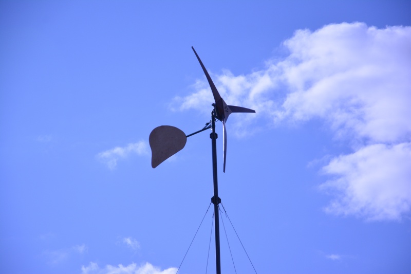
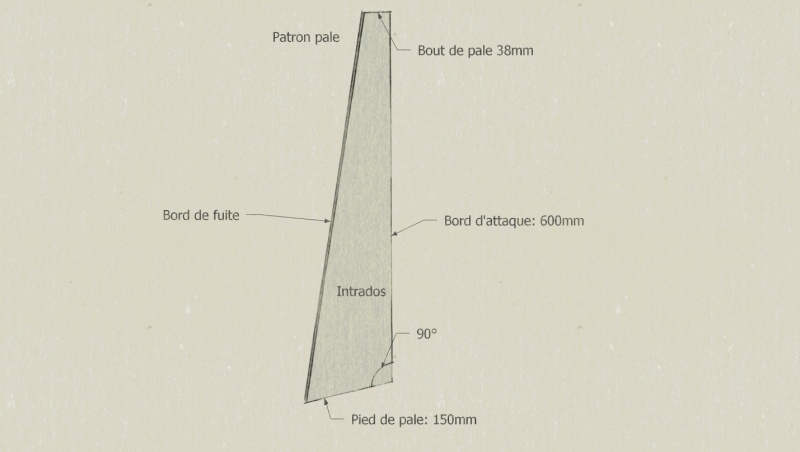

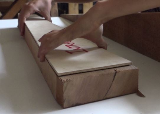

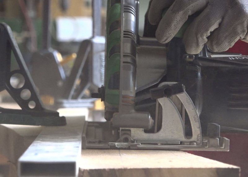
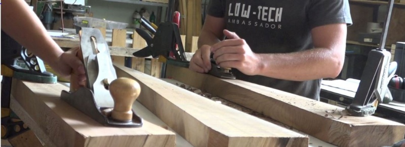
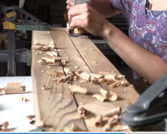
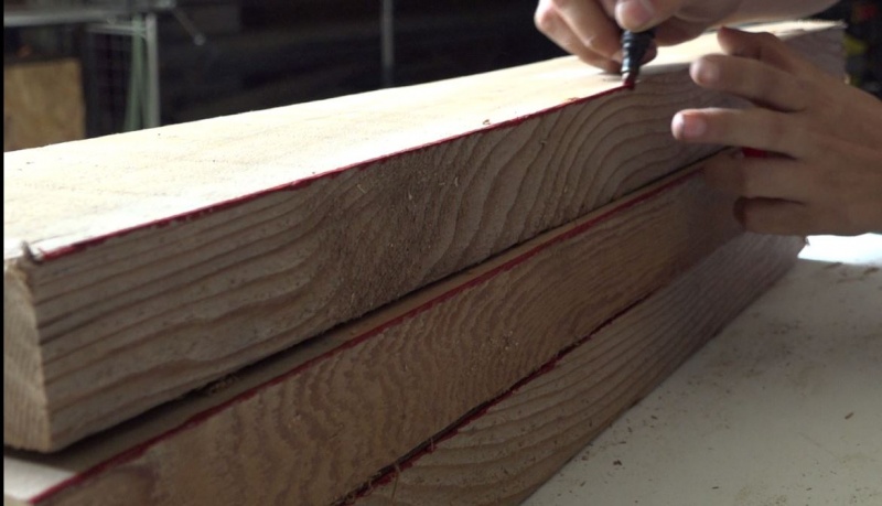
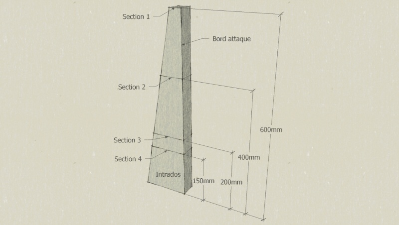
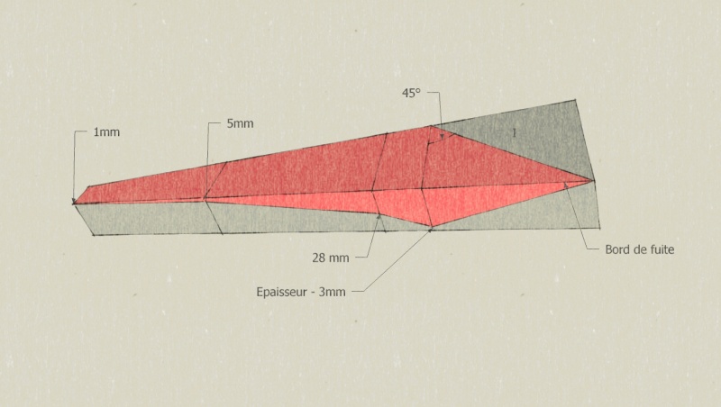
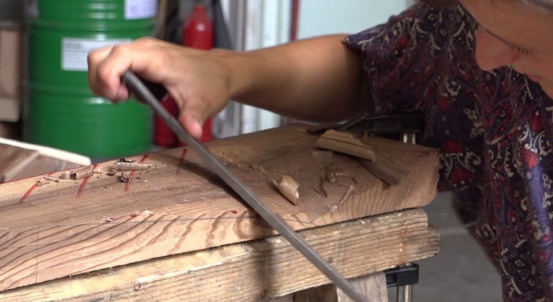
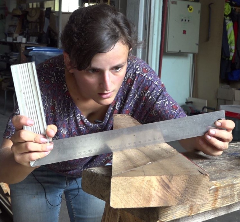
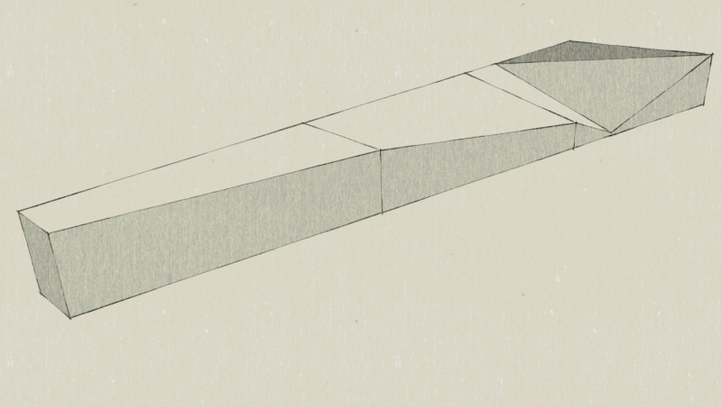
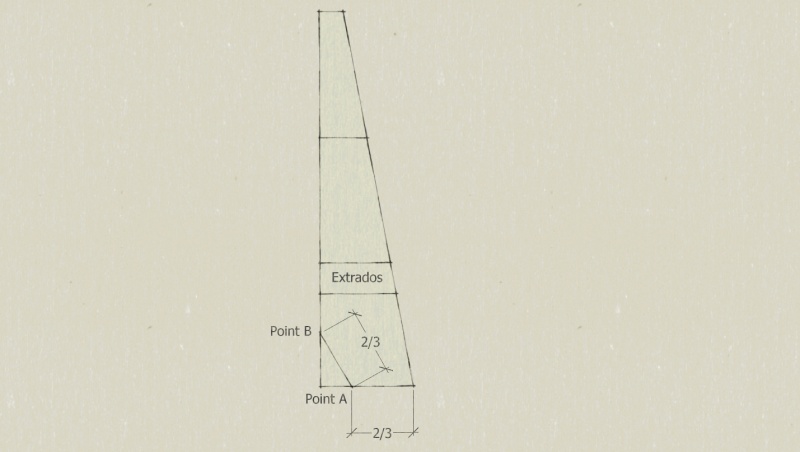
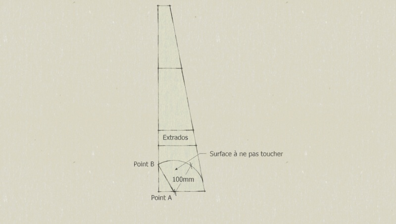
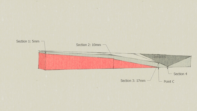
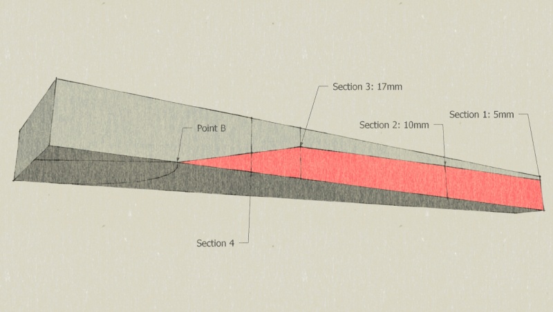
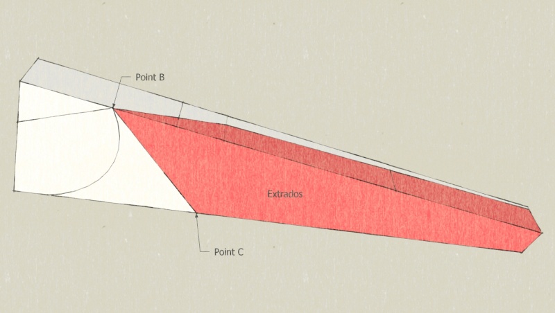
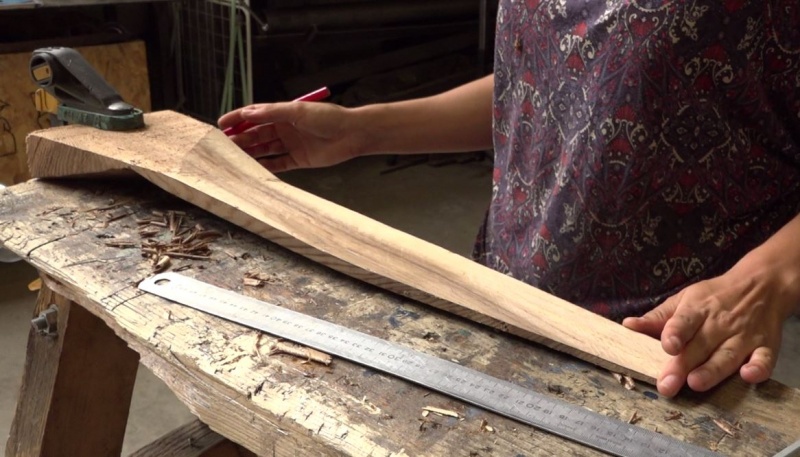
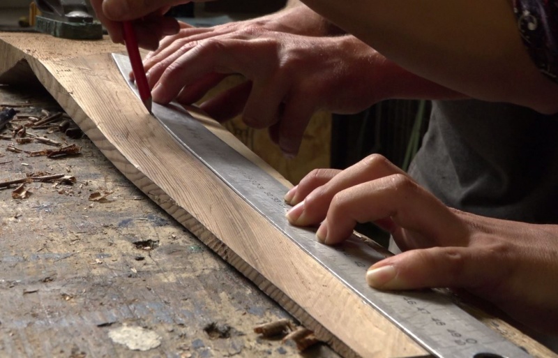
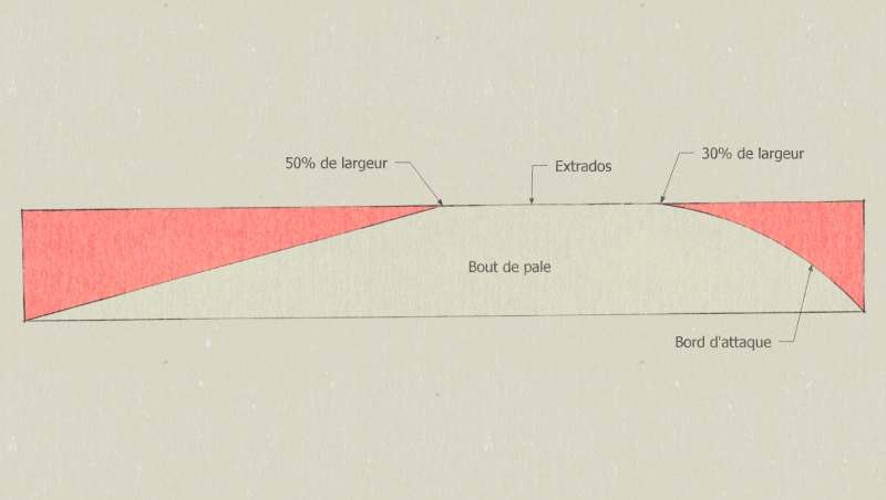
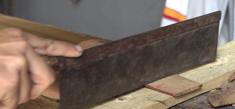
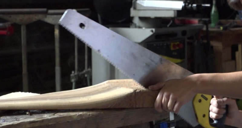
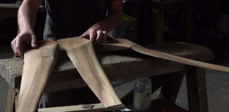
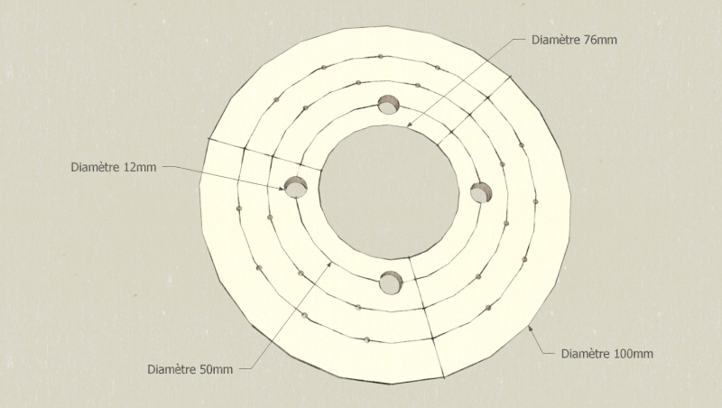
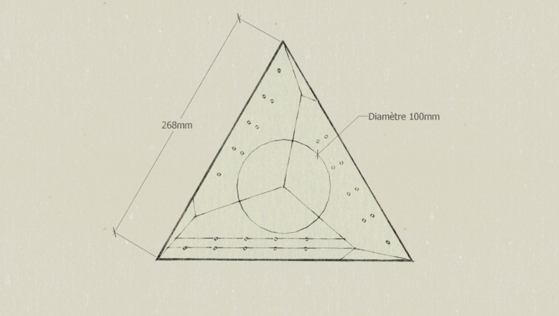
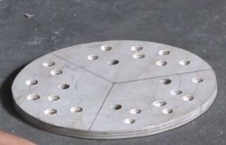
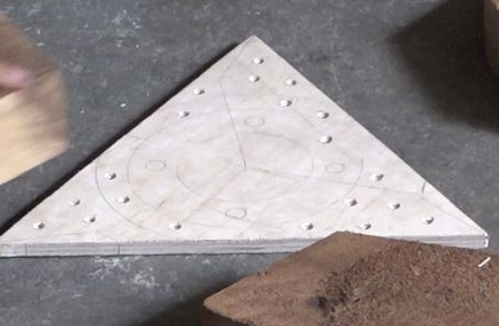
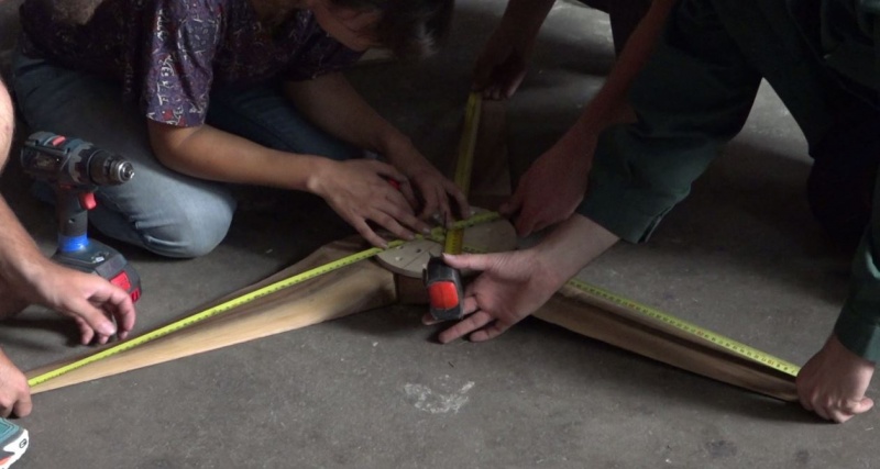
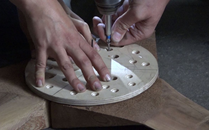
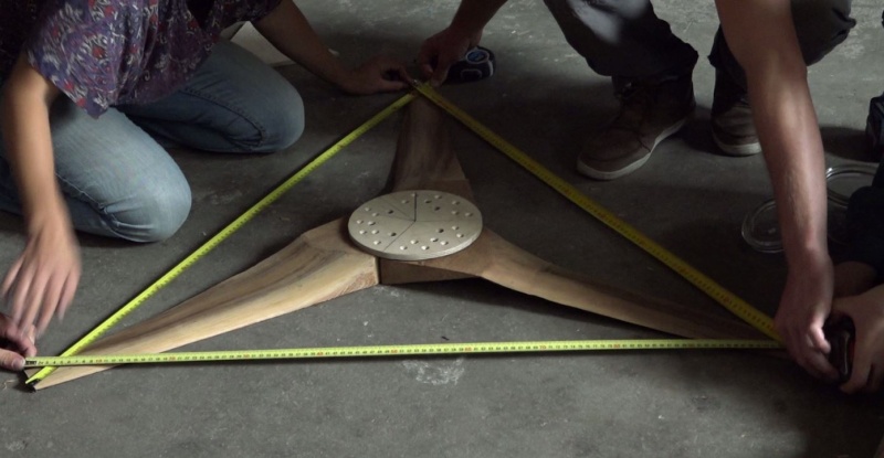
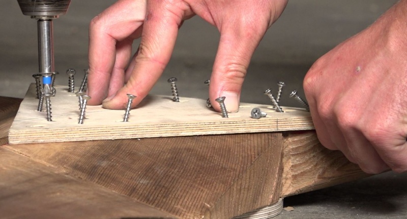
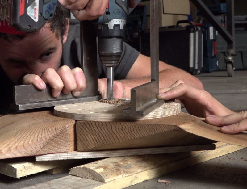
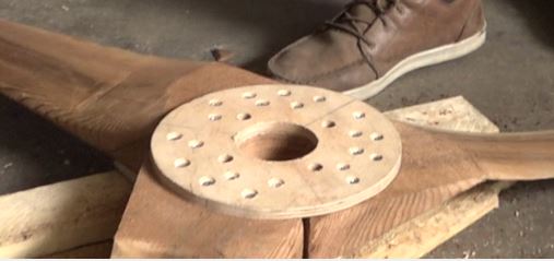
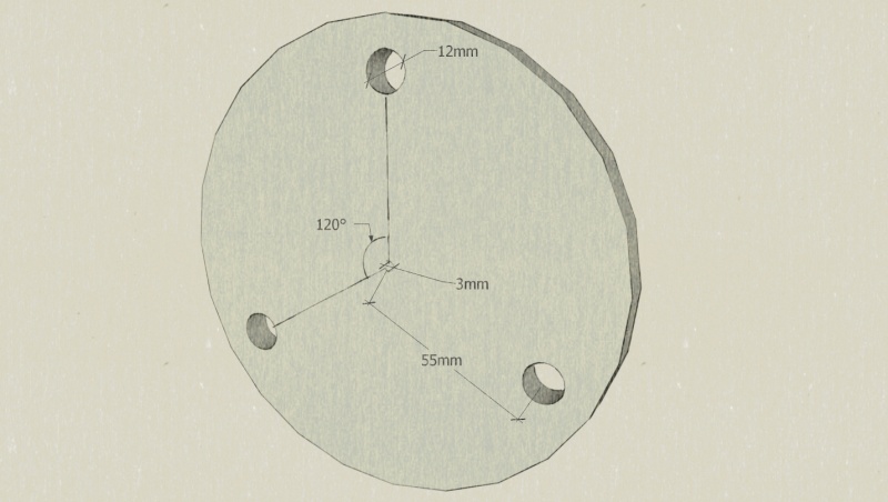
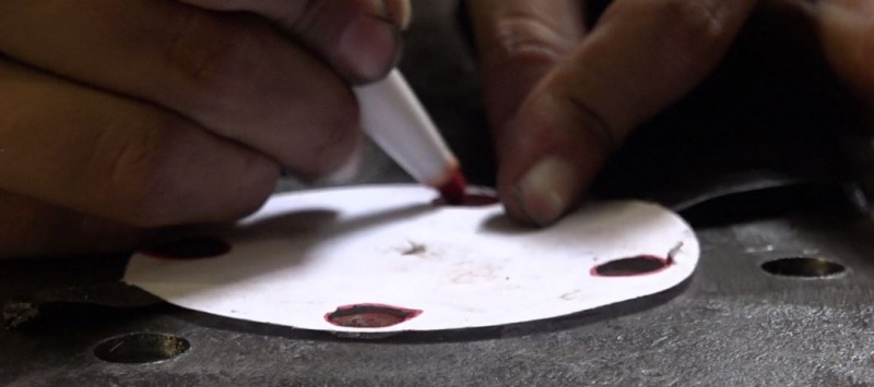
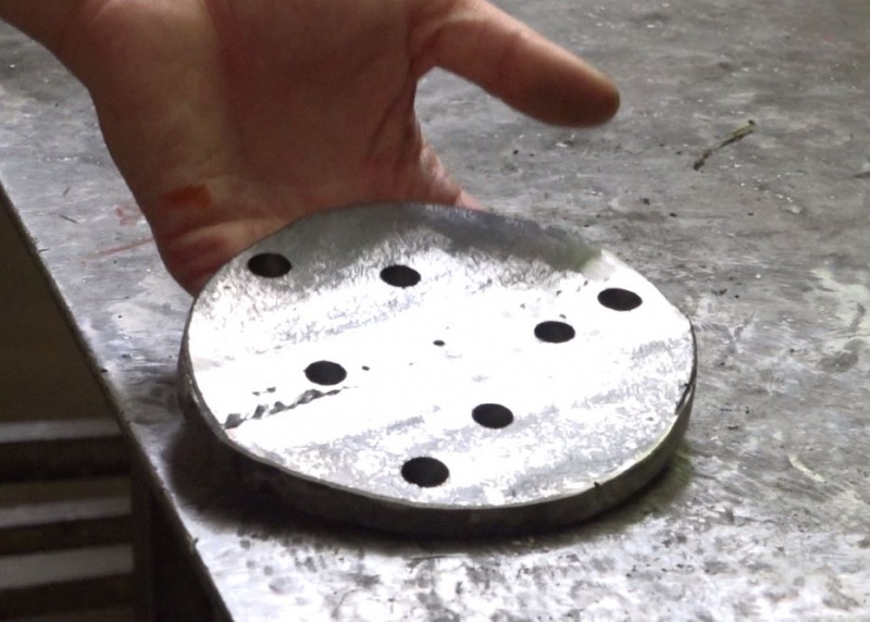
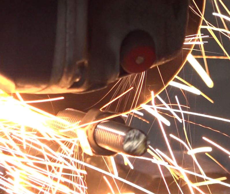
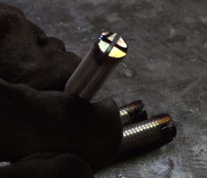
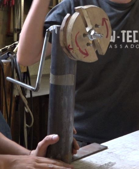
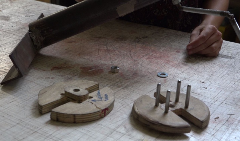
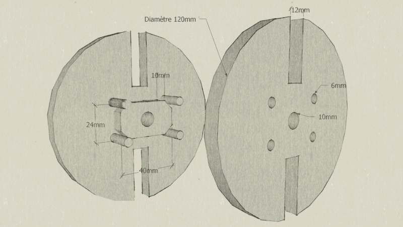
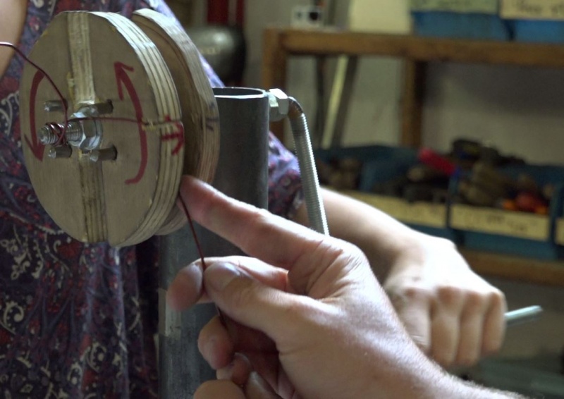
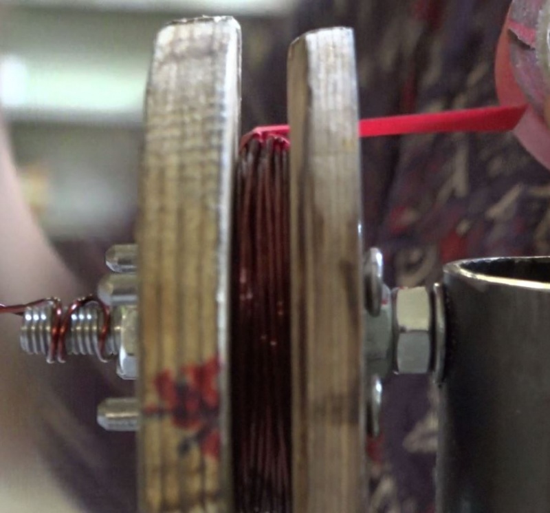
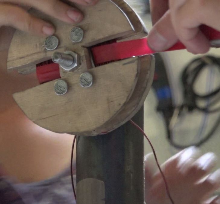
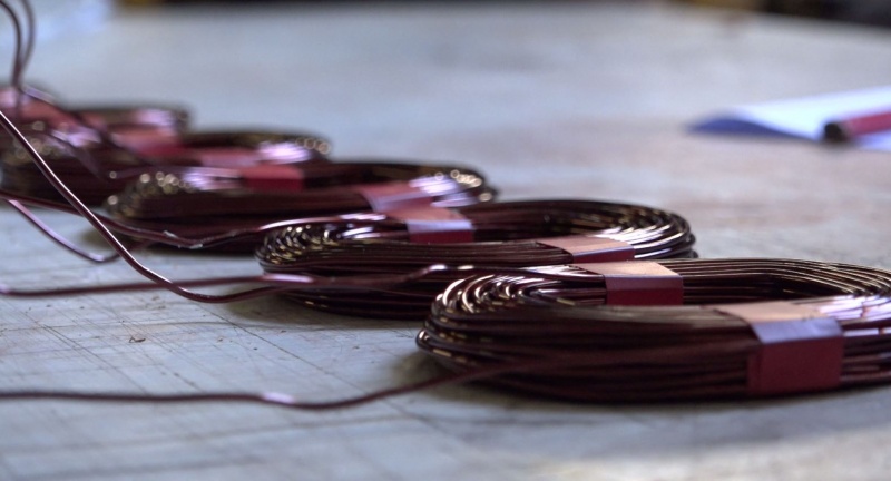
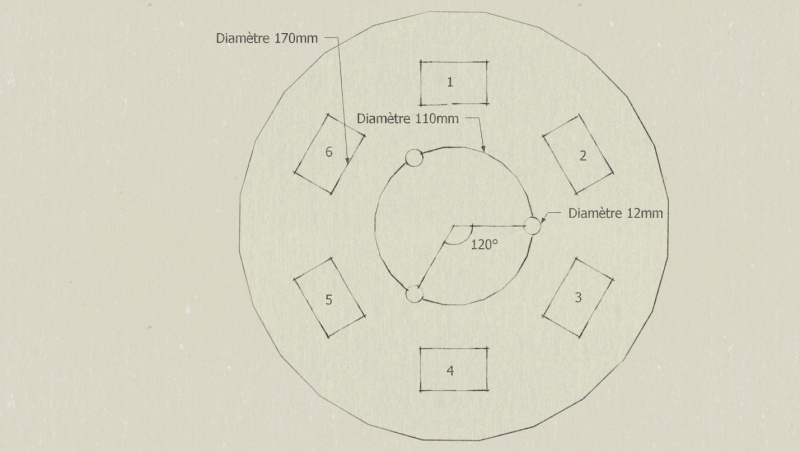
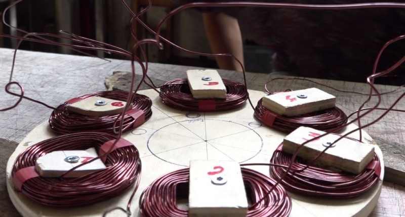
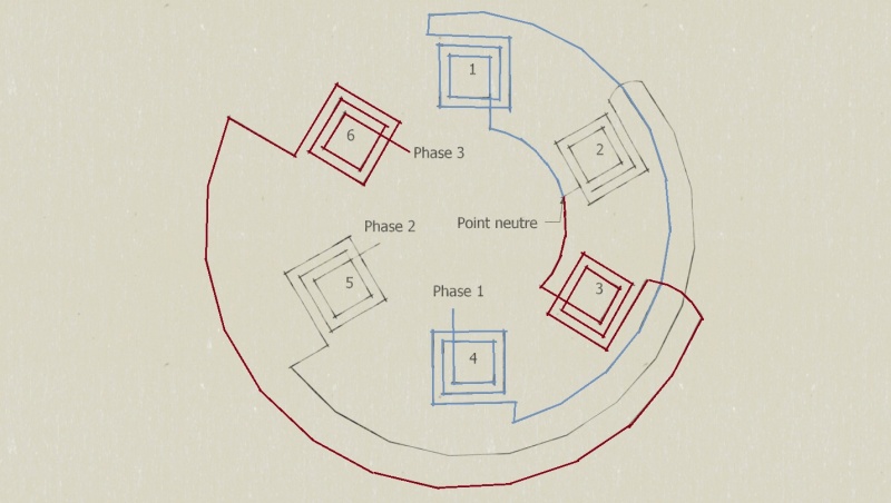
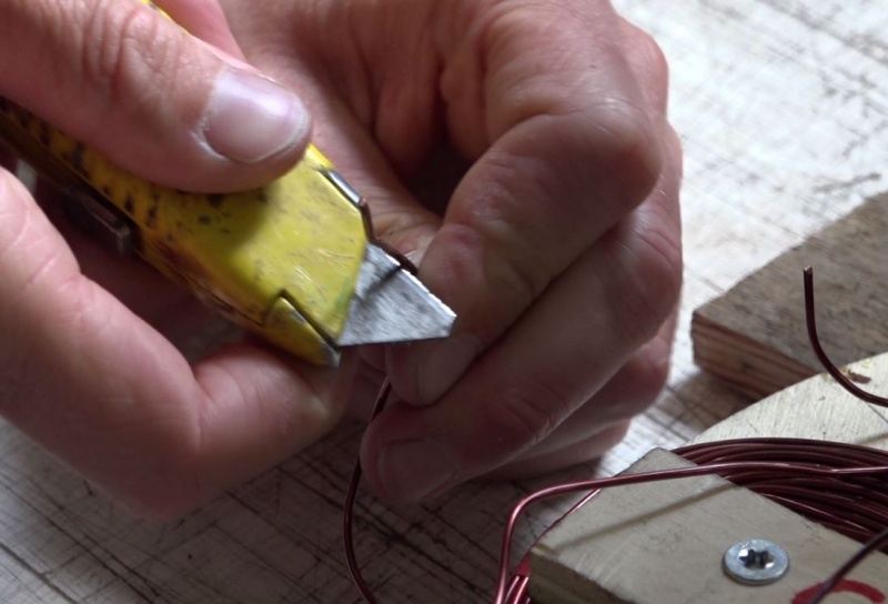
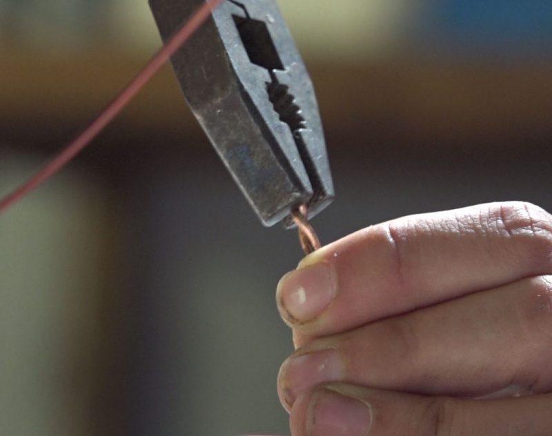
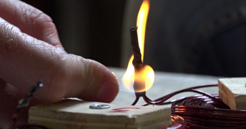
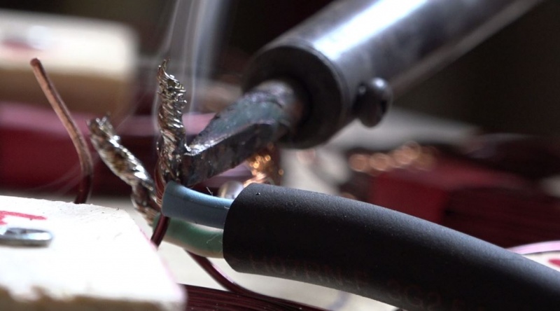
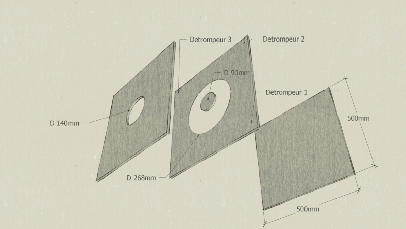
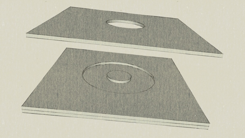
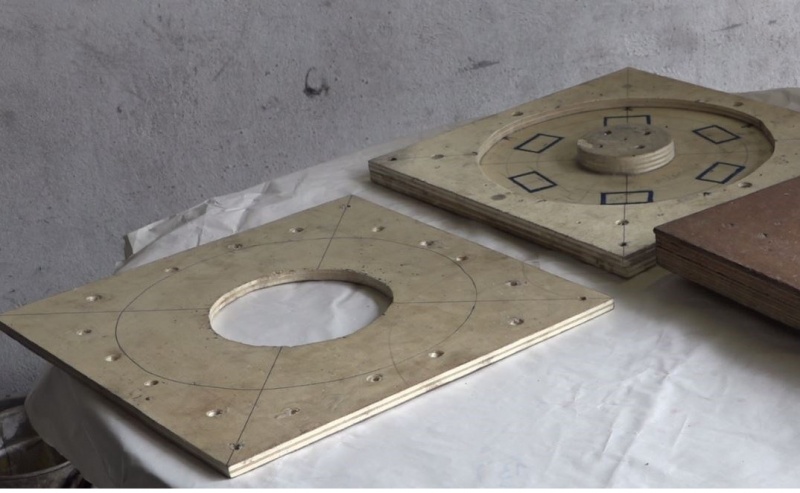
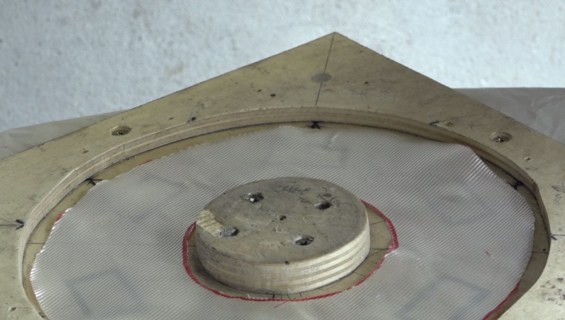
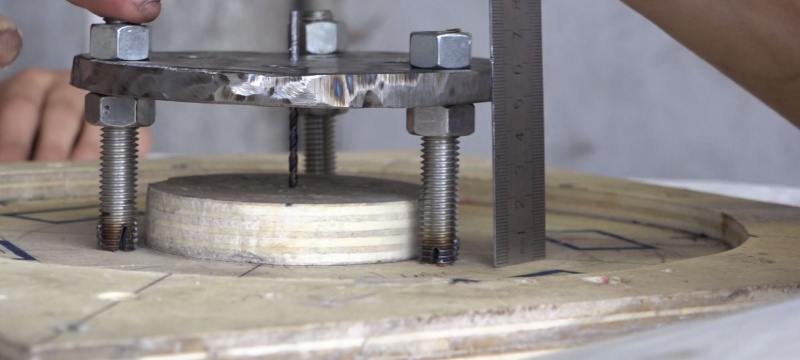
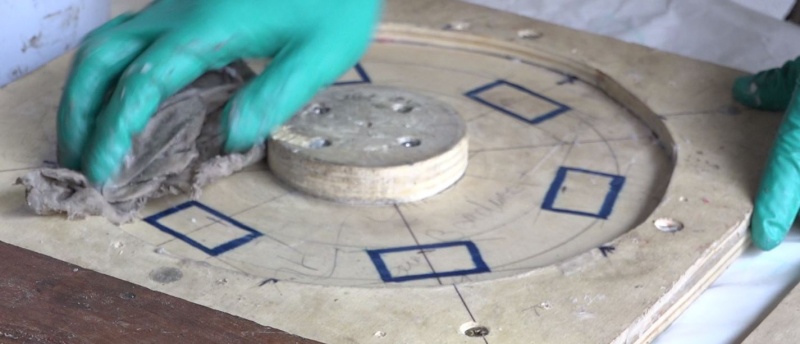
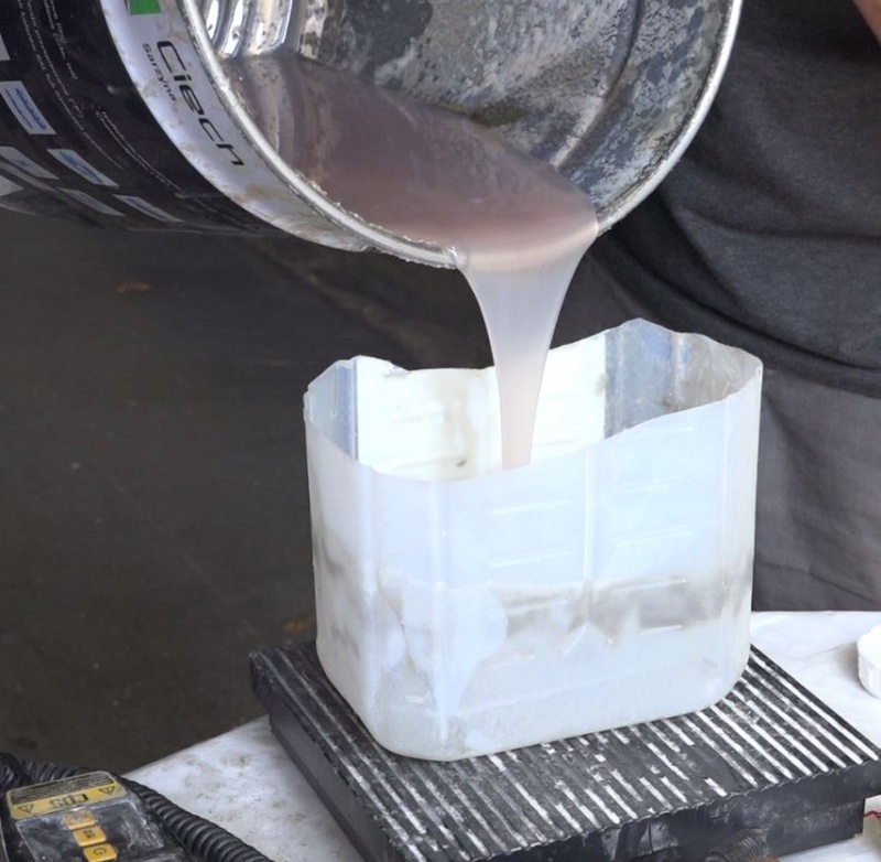
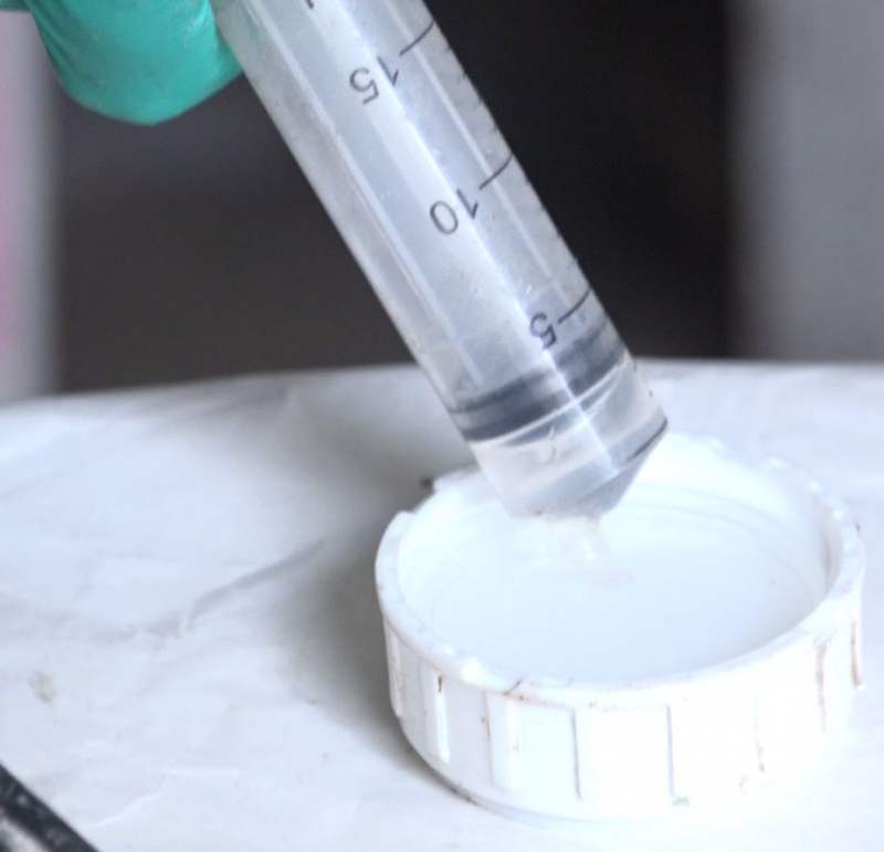
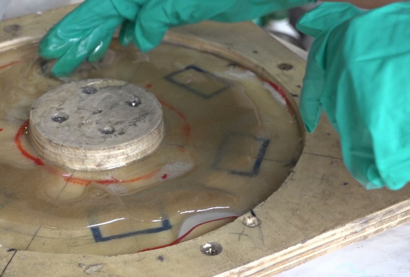
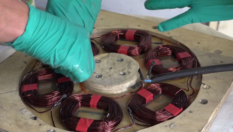
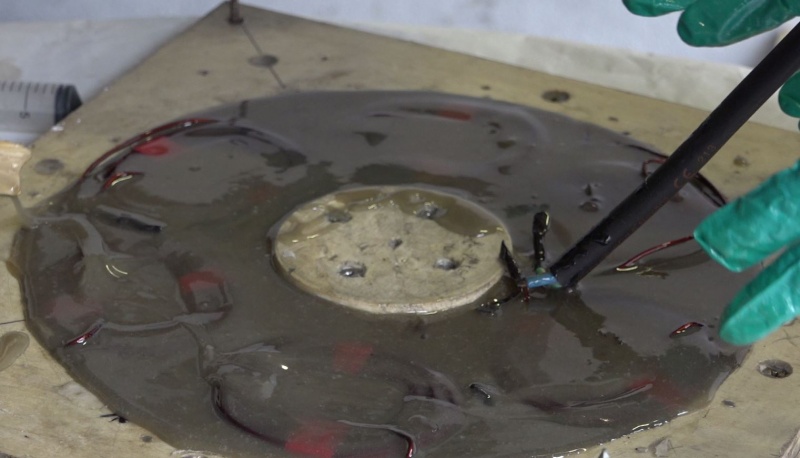
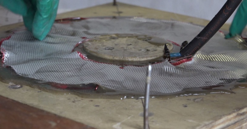
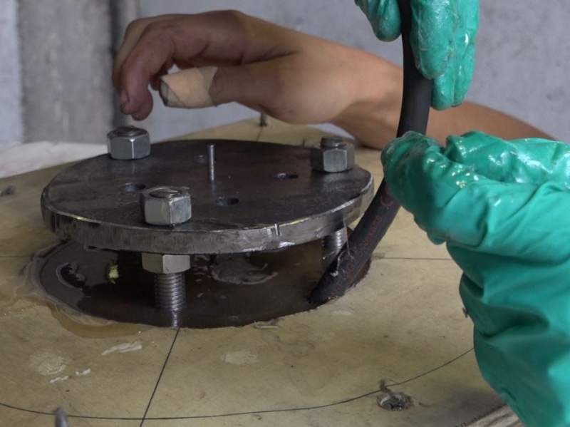
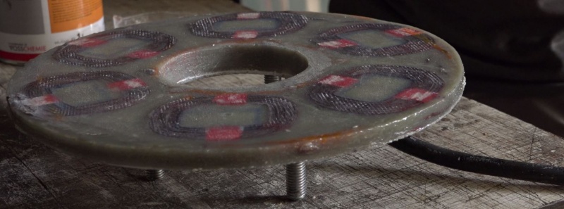
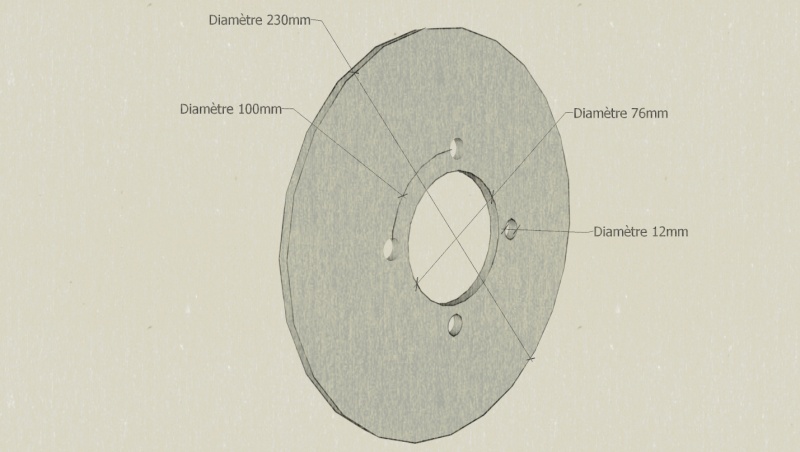
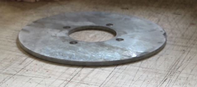
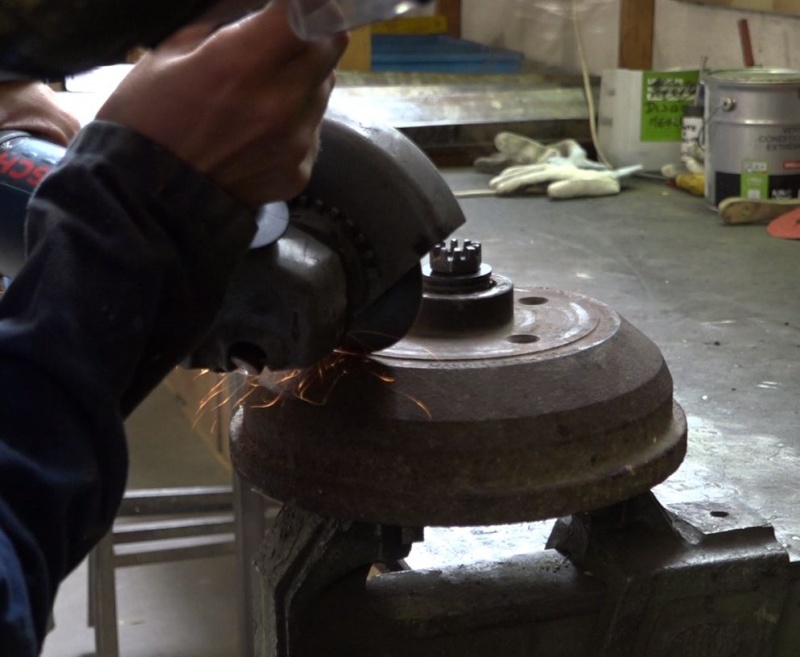
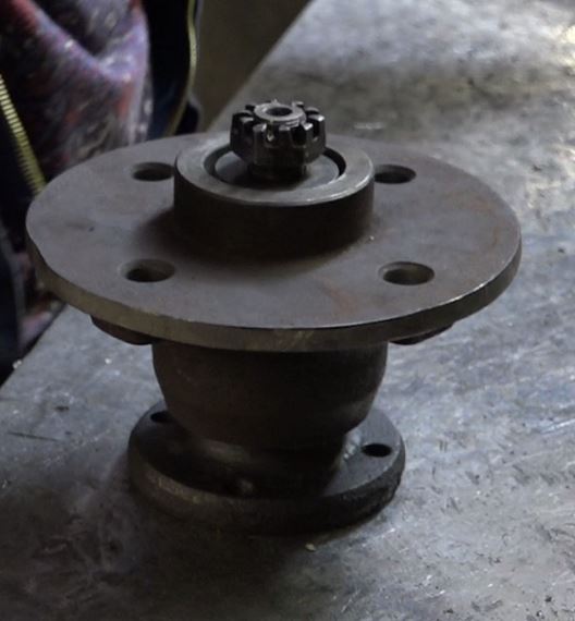
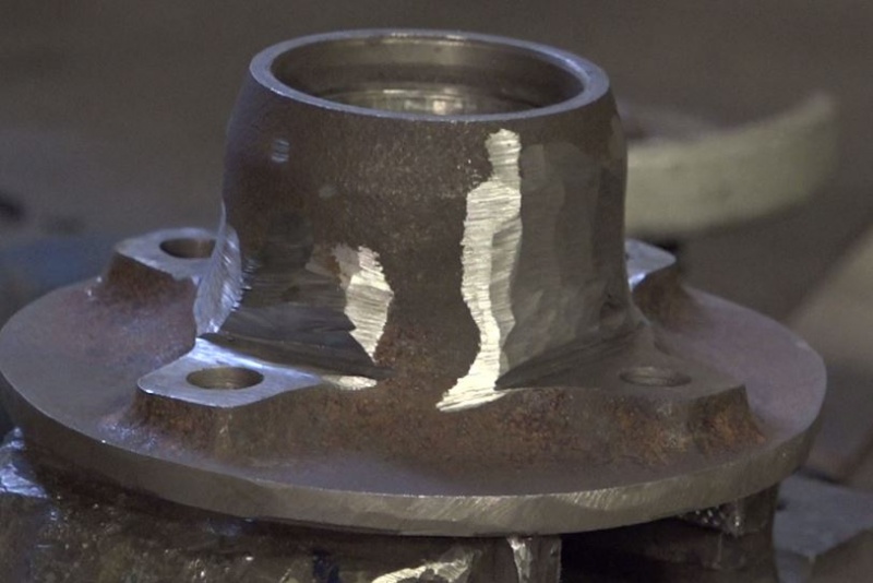
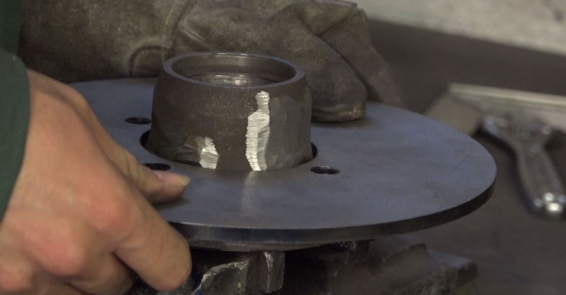
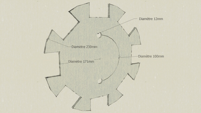
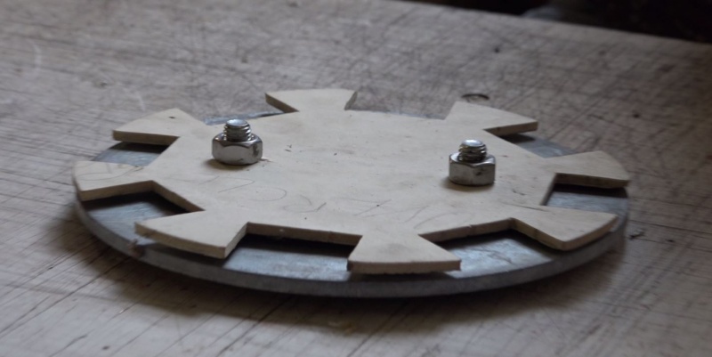
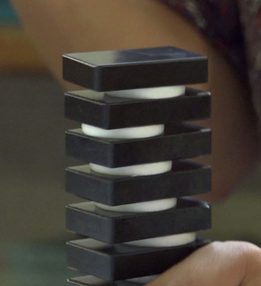
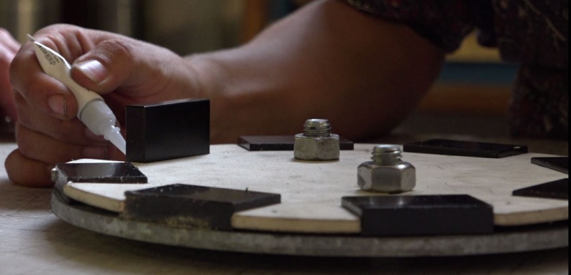
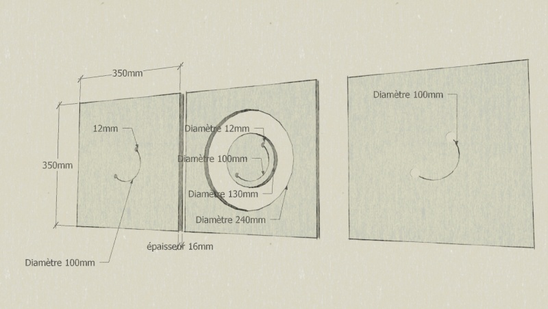
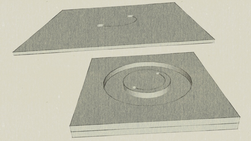
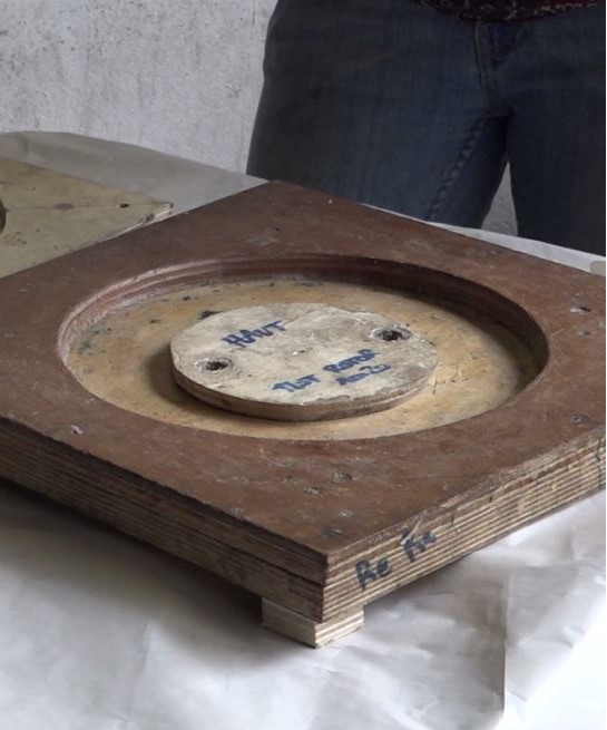
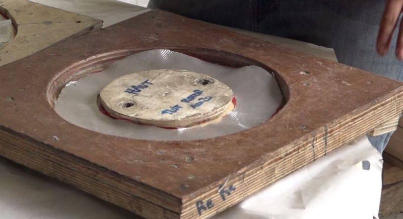

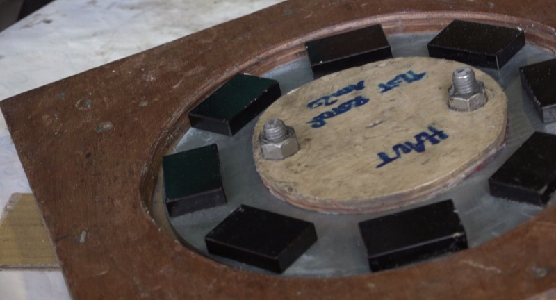
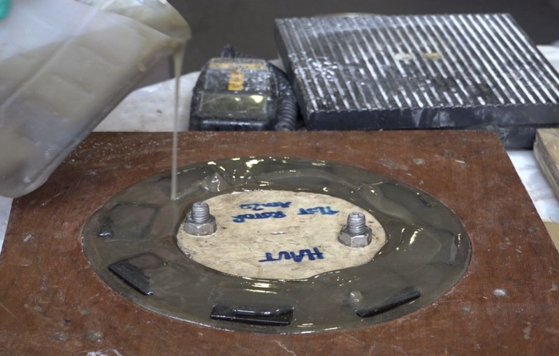
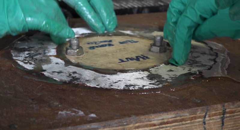
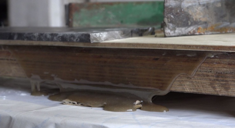
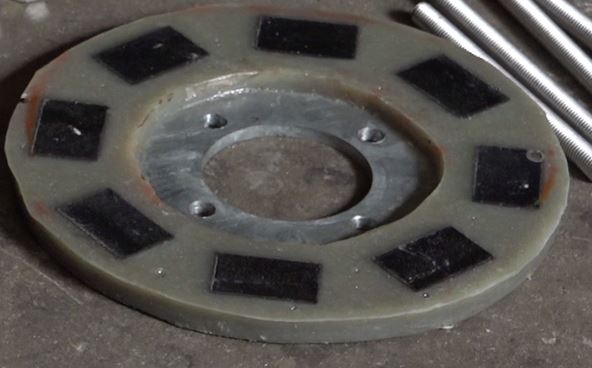
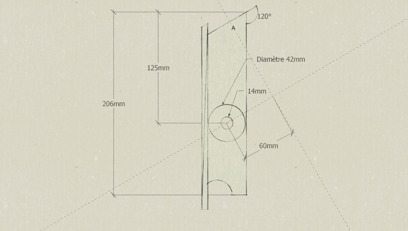
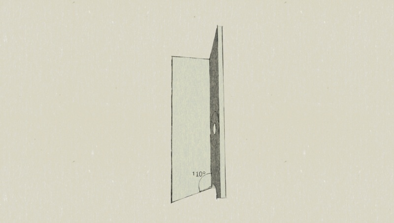
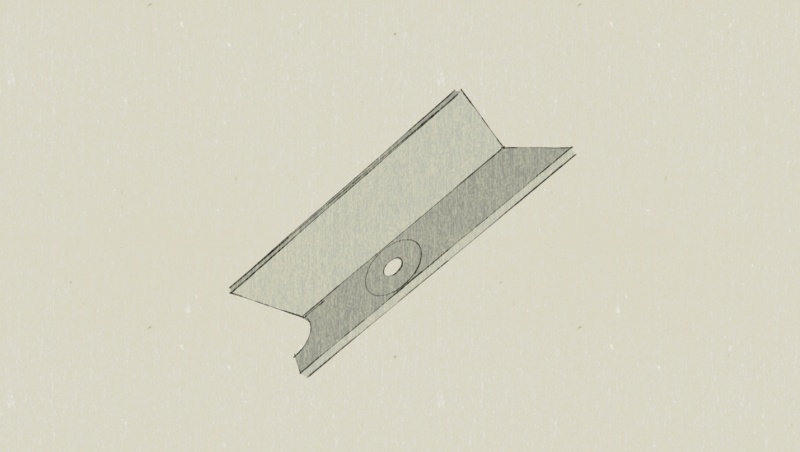
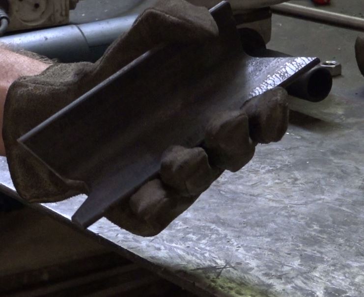
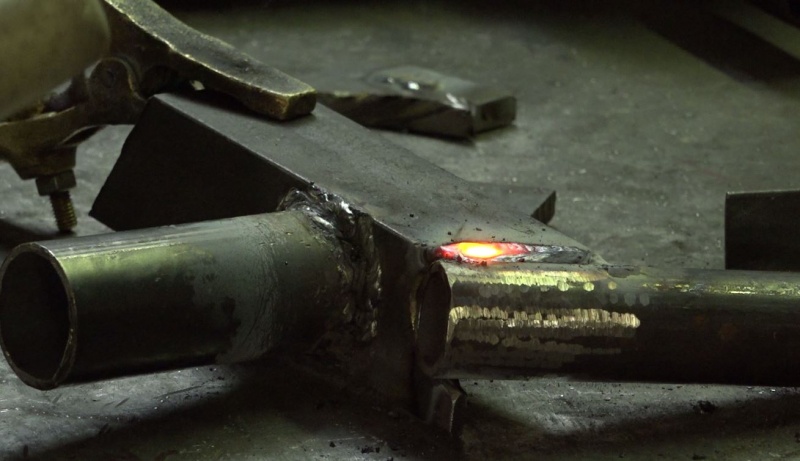
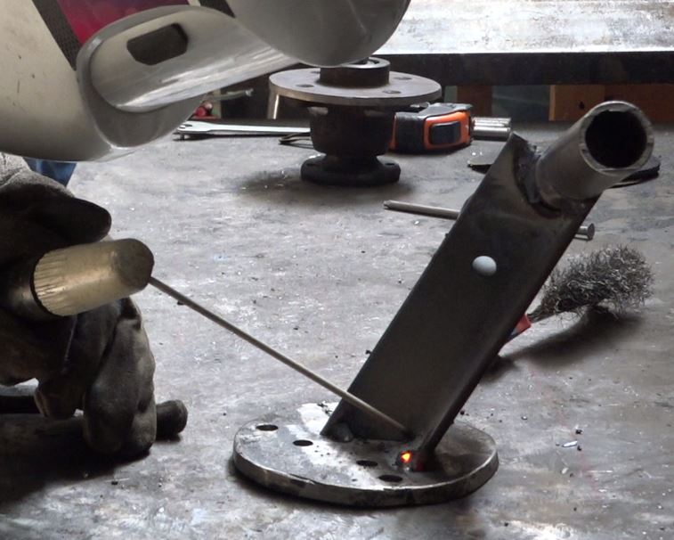
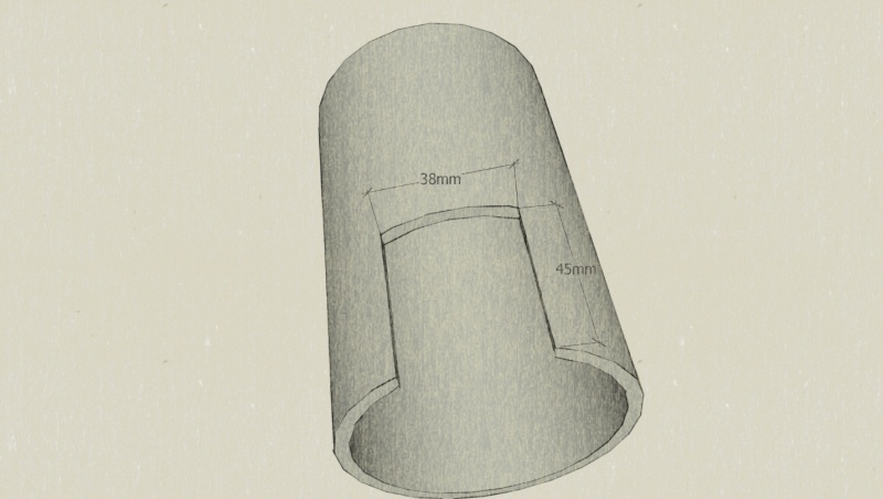
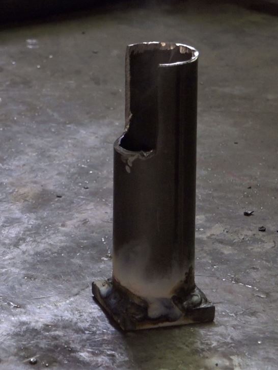
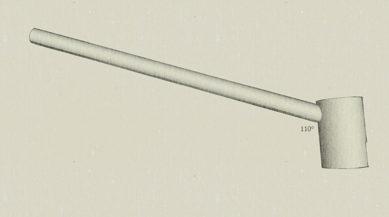
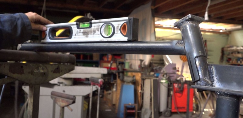
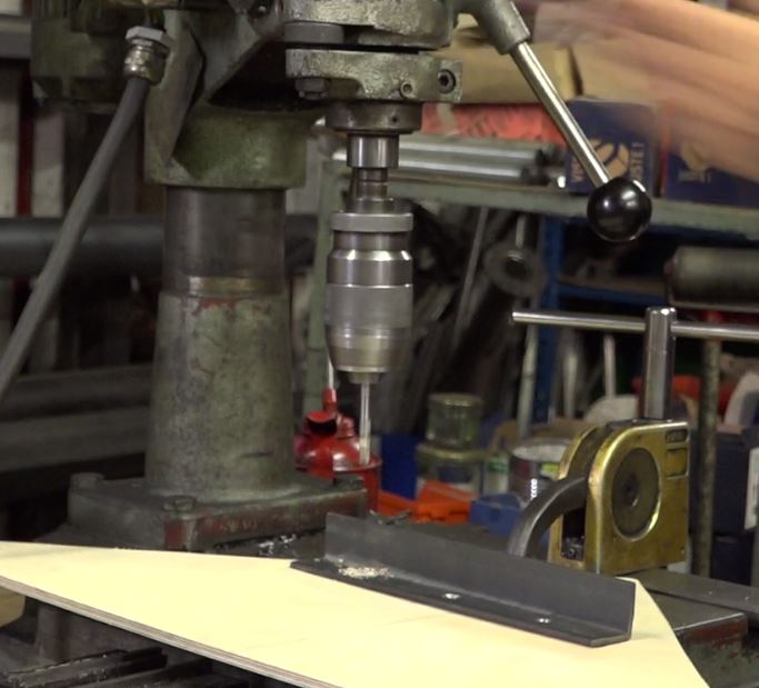
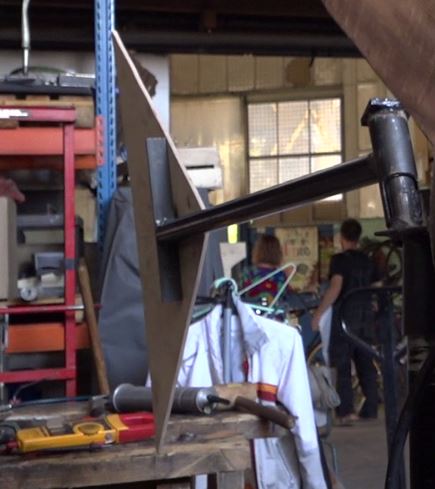
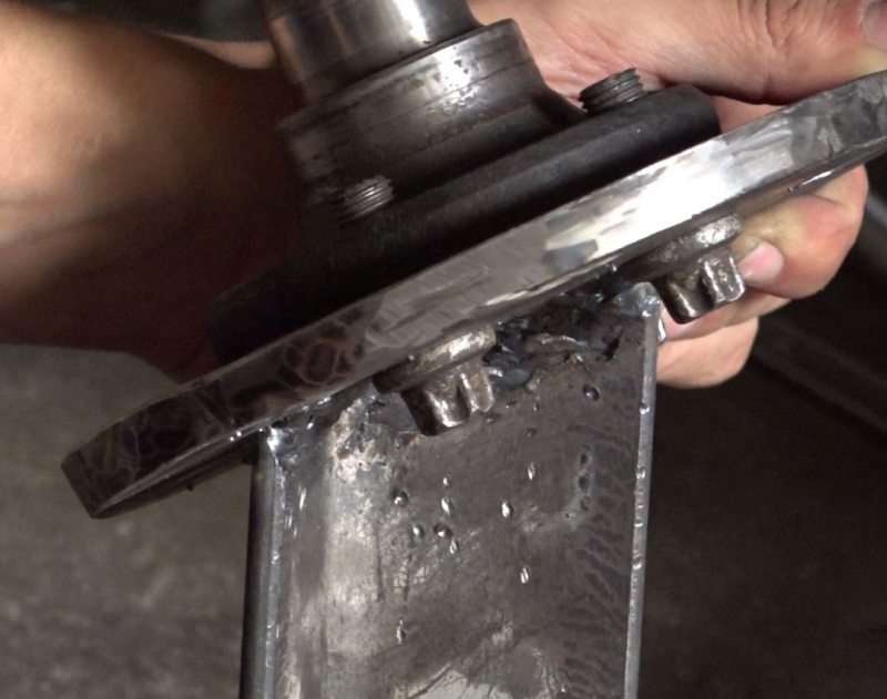
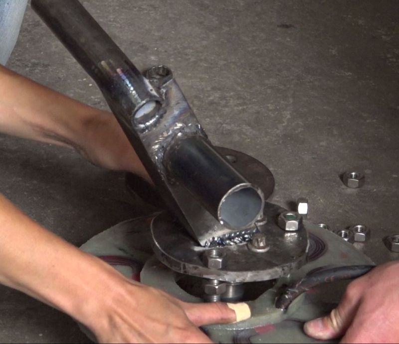
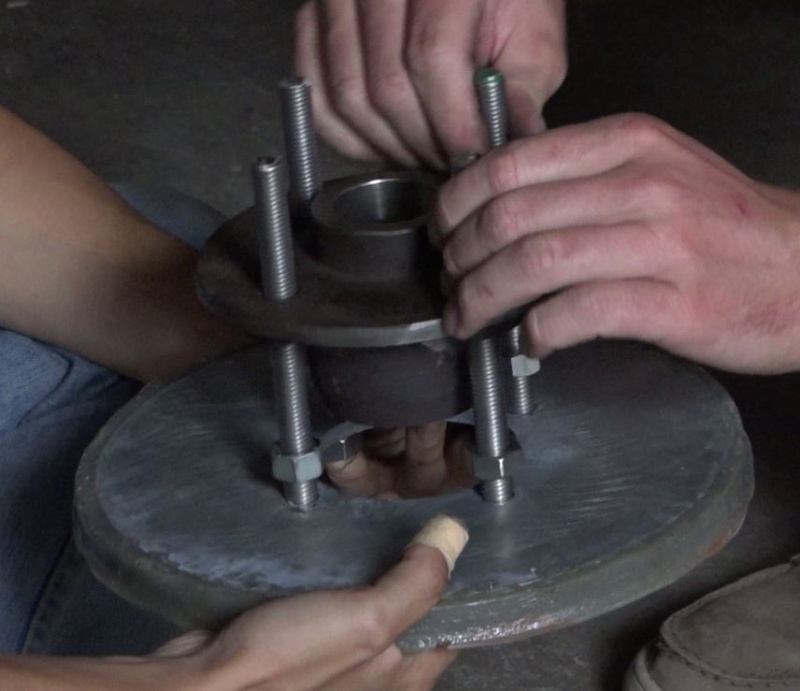
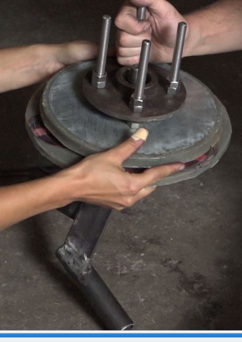
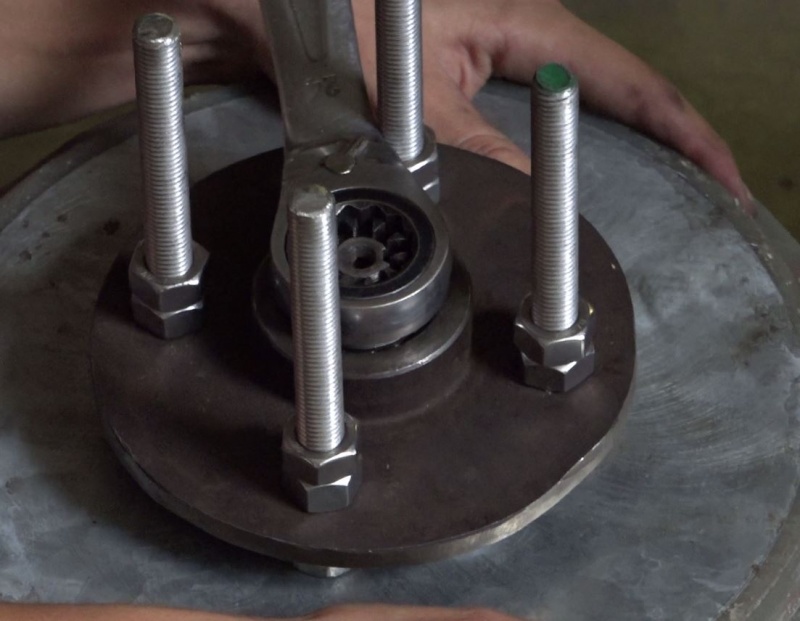
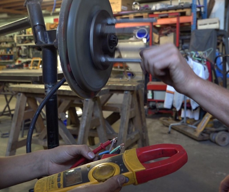
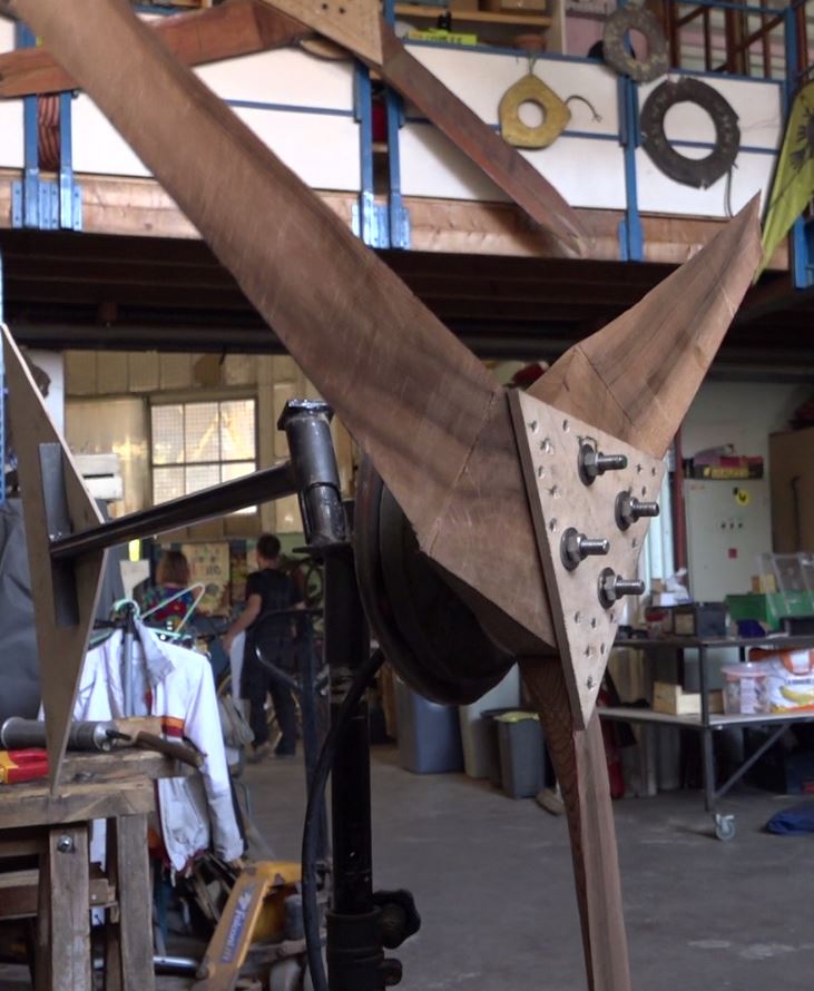
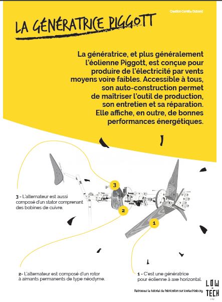
 Français
 English
 Deutsch
 Español
 Italiano
 Português