(Page créée avec « When you place your connector on a table with the plastic tab facing up, the right tab is your positive terminal, and the left tab is your negative terminal. ») |
(Mise à jour pour être en accord avec la nouvelle version de la source de la page) |
||
| (32 révisions intermédiaires par 3 utilisateurs non affichées) | |||
| Ligne 42 : | Ligne 42 : | ||
Their production is complex and the environmental impact when building | Their production is complex and the environmental impact when building | ||
a wind turbine isn't neutral at all. | a wind turbine isn't neutral at all. | ||
| − | Additionally up to today it isn't possible to repair a wind turbine for common people. | + | Additionally up to today it isn't possible to repair a wind turbine for common people. |
| Ligne 63 : | Ligne 63 : | ||
{{TutoVideo | {{TutoVideo | ||
|VideoType=Youtube | |VideoType=Youtube | ||
| − | |VideoURLYoutube=https:// | + | |VideoURLYoutube=https://youtu.be/8-WF1BH1cbs |
}} | }} | ||
{{Materials | {{Materials | ||
| Ligne 123 : | Ligne 123 : | ||
f - alligator clamps | f - alligator clamps | ||
| + | |||
| + | - Arc wielding station | ||
| Ligne 130 : | Ligne 132 : | ||
h - a soldering iron | h - a soldering iron | ||
| − | |Tuto_Attachments={{Tuto Attachments}} | + | |Tuto_Attachments={{Tuto Attachments |
| + | |Attachment=L_olienne_Eolienne_low_tech_5V___12V.pdf | ||
| + | }}{{Tuto Attachments | ||
| + | |Attachment=L_olienne_Affiche_Eolienne20W_FR.pdf | ||
| + | }} | ||
}} | }} | ||
{{Tuto Step | {{Tuto Step | ||
| Ligne 143 : | Ligne 149 : | ||
The blades rotate. | The blades rotate. | ||
| − | The rotor has 4 blades and is mounted on a mast in order to get more wind. | + | The rotor has 4 blades and is mounted on a mast in order to get more wind. |
| Ligne 161 : | Ligne 167 : | ||
| − | It consists of: | + | It consists of: |
-The rectifiers, which "rectify" the tension from the motor output | -The rectifiers, which "rectify" the tension from the motor output | ||
| Ligne 204 : | Ligne 210 : | ||
}} | }} | ||
{{Tuto Step | {{Tuto Step | ||
| − | |Step_Title= | + | |Step_Title=Wind turbine - The motor |
|Step_Content='''Choosing the motor''' | |Step_Content='''Choosing the motor''' | ||
| Ligne 215 : | Ligne 221 : | ||
The choice of motor will also be conditioned by the maximum voltage (Vmax). A motor characterized at 3V will deliver a much lower power than a motor characterized at 50V at the same rotation speed. Choose your motor (within the limit of the available choice) according to the desired application and the required power. | The choice of motor will also be conditioned by the maximum voltage (Vmax). A motor characterized at 3V will deliver a much lower power than a motor characterized at 50V at the same rotation speed. Choose your motor (within the limit of the available choice) according to the desired application and the required power. | ||
| − | |||
1 - Cut the 6 wires coming out of the stepper motor, strip and twist them. | 1 - Cut the 6 wires coming out of the stepper motor, strip and twist them. | ||
| Ligne 235 : | Ligne 240 : | ||
In fact, stepper motors are schematically made up of two or four coils: | In fact, stepper motors are schematically made up of two or four coils: | ||
| − | + | (picture 2) | |
| − | As described in the picture, in the case of a 6-wire we will not use the mid-point. In fact, we will accumulate two coils to make one and generate more tension. | + | As described in the picture, in the case of a 6-wire we will not use the mid-point. In fact, we will accumulate two coils to make one and generate more tension. |
| − | From this point, it's very simple: | + | From this point, it's very simple: |
| − | 1) Just put your multimeter in ohm meter mode, or even better in contact detection mode (you know when it does "BBIIIIPPPPP !!" when the two probes are touching ). | + | 1) Just put your multimeter in ohm meter mode, or even better in contact detection mode (you know when it does "BBIIIIPPPPP !!" when the two probes are touching ). |
| − | 2) The first step is to separate the two sets of wire for each coil. | + | 2) The first step is to separate the two sets of wire for each coil. |
| − | For a 4-wire system, it's very simple: you take one wire on one probe, and with the other probe you touch the other wires. When there is one that goes "BBBIIIIIPPPPP!!" or the measured resistance becomes low (it depends on the motor but a wide range would be 1 to 50 ohms) you are good you have found your coil and by elimination the two remaining wires are for the other coil. | + | For a 4-wire system, it's very simple: you take one wire on one probe, and with the other probe you touch the other wires. When there is one that goes "BBBIIIIIPPPPP!!" or the measured resistance becomes low (it depends on the motor but a wide range would be 1 to 50 ohms) you are good you have found your coil and by elimination the two remaining wires are for the other coil. |
For a 6 wire it is hardly more complex: we apply the same method to determine the sets of 3 wires per spool. Then we switch to ohmeter mode and look for which pair of wires per coil gives the highest pllus resistance ==> bingo you have found the right wires for one coil, repeat the operation for the other and you are good. | For a 6 wire it is hardly more complex: we apply the same method to determine the sets of 3 wires per spool. Then we switch to ohmeter mode and look for which pair of wires per coil gives the highest pllus resistance ==> bingo you have found the right wires for one coil, repeat the operation for the other and you are good. | ||
| Ligne 252 : | Ligne 257 : | ||
|Step_Picture_00=L_olienne_1_-_Tester_les_couples_de_fils.jpg | |Step_Picture_00=L_olienne_1_-_Tester_les_couples_de_fils.jpg | ||
|Step_Picture_01=Mini__olienne_30W_4ou6fils-e49e5.jpg | |Step_Picture_01=Mini__olienne_30W_4ou6fils-e49e5.jpg | ||
| + | |Step_Picture_02=L_olienne_Module5v.png | ||
}} | }} | ||
{{Tuto Step | {{Tuto Step | ||
|Step_Title=The Wind Turbine - Motor Axis | |Step_Title=The Wind Turbine - Motor Axis | ||
| − | |Step_Content=1 - Cutting a metal plate of 80x30 cm. Drill it with 5 holes of diameter 4mm. | + | |Step_Content=1 - Cutting a metal plate of 80x30 cm. Drill it with 5 holes of diameter 4mm. |
''* Tip: You can use figure 1 above to cut and drill the plate.'' | ''* Tip: You can use figure 1 above to cut and drill the plate.'' | ||
| Ligne 269 : | Ligne 275 : | ||
[[Fichier:L olienne - quipe des l phants - Hack le Lab Formule puissance vent.gif|100px]] | [[Fichier:L olienne - quipe des l phants - Hack le Lab Formule puissance vent.gif|100px]] | ||
| − | This formula can be used to calculate the length of the blades of the wind turbine: | + | This formula can be used to calculate the length of the blades of the wind turbine: |
[[Fichier:L olienne - quipe des l phants - Hack le Lab Relation longueur pale - vitesse vent.gif|200px]] | [[Fichier:L olienne - quipe des l phants - Hack le Lab Relation longueur pale - vitesse vent.gif|200px]] | ||
| Ligne 323 : | Ligne 329 : | ||
{{Tuto Step | {{Tuto Step | ||
|Step_Title=The electrical circuit - Rectifiers | |Step_Title=The electrical circuit - Rectifiers | ||
| − | |Step_Content=The electrical circuit is as shown in "Figure 4". | + | |Step_Content=The electrical circuit is as shown in "Figure 4". |
At the output of the engine, we get alternating current (AC). However, to charge a battery or light a lamp, it is necessary to have direct current (DC). Two rectifiers are used to transform alternating current into direct current: they "rectify" the voltage at the output of the motor. | At the output of the engine, we get alternating current (AC). However, to charge a battery or light a lamp, it is necessary to have direct current (DC). Two rectifiers are used to transform alternating current into direct current: they "rectify" the voltage at the output of the motor. | ||
| Ligne 348 : | Ligne 354 : | ||
|Step_Title=The electrical circuit - Capacitor | |Step_Title=The electrical circuit - Capacitor | ||
|Step_Content=The energy supplied by the wind turbine is not constant because the wind speed is constantly changing. The overload must therefore be temporarily stored in order to | |Step_Content=The energy supplied by the wind turbine is not constant because the wind speed is constantly changing. The overload must therefore be temporarily stored in order to | ||
| − | to be able to redistribute it consistently. A capacitor is used for this purpose. | + | to be able to redistribute it consistently. A capacitor is used for this purpose. |
The capacitor is a polarized component: | The capacitor is a polarized component: | ||
- the positive terminal is the longest leg | - the positive terminal is the longest leg | ||
| − | - the negative terminal is the shortest leg | + | - the negative terminal is the shortest leg |
''* Tip: It is also possible to refer to the "-" symbol written on the minus pole.'' | ''* Tip: It is also possible to refer to the "-" symbol written on the minus pole.'' | ||
| Ligne 382 : | Ligne 388 : | ||
|Step_Content=When you place your connector on a table with the plastic tab facing up, the right tab is your positive terminal, and the left tab is your negative terminal. | |Step_Content=When you place your connector on a table with the plastic tab facing up, the right tab is your positive terminal, and the left tab is your negative terminal. | ||
| − | 1 | + | 1 - Solder a red wire to the positive terminal and a black wire to the negative terminal. These will be the output wires of your wind turbine, to which you can connect a battery, a light bulb, etc, and in this case a USB port. (picture 11) |
| − | 2 | + | 2 - Solder the red wire to the regulator output and the black wire to the regulator common. (image 12)''. |
| − | + | Your circuit's ready to go. You can connect a telephone to it, provided there is wind of course.''(picture 13)' | |
| − | ''( | ||
|Step_Picture_00=L_olienne_11_-_Raccord_USB.jpg | |Step_Picture_00=L_olienne_11_-_Raccord_USB.jpg | ||
|Step_Picture_01=L_olienne_12_-_Entre_e_re_gulateur.jpg | |Step_Picture_01=L_olienne_12_-_Entre_e_re_gulateur.jpg | ||
| Ligne 393 : | Ligne 398 : | ||
}} | }} | ||
{{Tuto Step | {{Tuto Step | ||
| − | |Step_Title= | + | |Step_Title=Motor protection |
| − | |Step_Content= | + | |Step_Content=Cover the engine and the inner tube electrical circuit: this will protect them from rain or sea spray. |
| − | ''( | + | ''(picture 14)'' |
|Step_Picture_00=L_olienne_14_-_Prote_ger_syste_me.jpg | |Step_Picture_00=L_olienne_14_-_Prote_ger_syste_me.jpg | ||
}} | }} | ||
{{Tuto Step | {{Tuto Step | ||
| − | |Step_Title= | + | |Step_Title=Use |
| − | |Step_Content= | + | |Step_Content=Connect a mobile phone or other device with a USB connection to the electrical circuit and let it charge for a few hours. |
| − | + | In an average wind, allow 5 hours of charging time for a phone battery. | |
| − | + | }} | |
| + | {{Tuto Step | ||
| + | |Step_Title= | ||
| + | |Step_Content='''Got two minutes? Whether or not you would like to do this low-tech, your answer to [https://framaforms.org/votre-avis-sur-ce-tutoriel-du-low-tech-lab-1589450161 this form] would help us improve our tutorials. Thank you in advance for your help!''' | ||
| + | |||
| + | As all the work of the Low-tech Lab, ''this tutorial is participative''. Please do not hesitate to add the modifications which seem important to you, and to share your achievements in comments. | ||
| + | }} | ||
| + | {{Tuto Step | ||
| + | |Step_Title=Contenu pédagogique à télécharger | ||
| + | |Step_Content=Vous pouvez télécharger une fiche pédagogique créée par le Low-tech Lab dans la partie "Fichiers" du tutoriel (onglet au niveau de la section "Outils-Matériaux"). | ||
| + | |Step_Picture_00=L_olienne__olienne.JPG | ||
}} | }} | ||
{{Notes | {{Notes | ||
| − | |Notes= | + | |Notes=<div class="mw-translate-fuzzy"> |
| + | Feel free to comment, share, and enhance the tutorial with useful information to improve it. | ||
| + | </div> | ||
| + | <div class="mw-translate-fuzzy"> | ||
| + | FIND THE SKAVENJY TUTORIAL, inspired by this model: [https://www.skavenji.fr/wp-content/uploads/2019/09/TUTORIEL-EOLIENNE-LOW-TECH-SKAVENJI.pdf Click here] | ||
| + | </div> | ||
| − | + | <div class="mw-translate-fuzzy"> | |
| + | Find detailed information on self-built wind turbines on the website [http://www.kdwindturbines.nl/ www.kdwindturbines.nl]. Many reports are available, and the document [https://kdwindturbines.nl/wp-content/uploads/2021/05/Sequence-of-KD-reports-for-self-study.pdf Reports for self-study] provides an overview of the reports recommended for the study the different technical parts of a wind turbine. For more information about different types of safety systems which turn the rotor out of the wind in case of high winds, have a look on the [https://kdwindturbines.nl/wp-content/uploads/2020/02/KD-485.pdf public report KD 485]. | ||
| + | </div> | ||
| + | }} | ||
| + | {{PageLang | ||
}} | }} | ||
{{Tuto Status | {{Tuto Status | ||
Version actuelle datée du 6 février 2023 à 14:26
Description
Create an wind turbine from stepper motors from an old printer.
Sommaire
Sommaire
- 1 Description
- 2 Sommaire
- 3 Introduction
- 4 Video d'introduction
- 5 Étape 1 - How it Works
- 6 Étape 2 - Steps Involved in Making the System
- 7 Étape 3 - Wind turbine - The motor
- 8 Étape 4 - The Wind Turbine - Motor Axis
- 9 Étape 5 - The Wind Turbine - Blade Preparation
- 10 Étape 6 - The Wind Turbine - Fins and Blade Bases
- 11 Étape 7 - The Wind Turbine - Assembly
- 12 Étape 8 - The electrical circuit - Rectifiers
- 13 Étape 9 - The electrical circuit - Capacitor
- 14 Étape 10 - The electrical circuit - Voltage regulator or voltage booster
- 15 Étape 11 - The electrical circuit - Connecting the USB port
- 16 Étape 12 - Motor protection
- 17 Étape 13 - Use
- 18 Étape 14 -
- 19 Étape 15 - Contenu pédagogique à télécharger
- 20 Notes et références
- 21 Commentaires
Introduction
In Africa, almost 600 million people in rural areas don't have access to electricity.
Context :
Access to energy and in particular access to electricity is an indispensable condition for a country's economic and sanitary development.
Although the worldwide energy consumption has almost doubled since 1970, it hasn't increased much in poorer countries. To this day approximately 2 billion people can't rely on having access to enough energy for living under reasonable conditions and 1.6 billion people don't have access to electricity at all. Consequences for environment and sanitary conditions are enormous.
Renewable energies like the wind turbine might be a solution: A wind turbine converts kinetic energy in the form of wind into electrical energy.
Industrial wind turbines
An industrial wind turbine with a power output of 2 megawatts produces about 4400 megawatt hours per year, which is equal to the consumption of around 2000 people. Industrial wind turbines are full of sensors, movable parts, controllers and mechanical parts in general. Their production is complex and the environmental impact when building a wind turbine isn't neutral at all. Additionally up to today it isn't possible to repair a wind turbine for common people.
The low-tech wind turbine
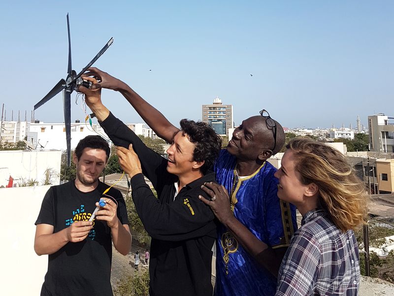
A low tech wind turbine for less than 10€, simple to build from recycled parts, that's possible. Despite their slight power output compared to industrial wind turbines, they are quite good for many local applications like charging a mobile phone, powering LEDs or a little pump. For these applications some watts will be sufficient.
This wind turbine might therefore be very useful for remote areas without an electricity grid but with favorable winds. In Senegal e.g. only 40 per cent of the population is connected connected to the electricity grid in urban zones and only 10 per cent in rural areas. The ability to generate electricity with the help of a self-built wind turbine
provides a good opportunity.Youtube
Matériaux
Wind turbine
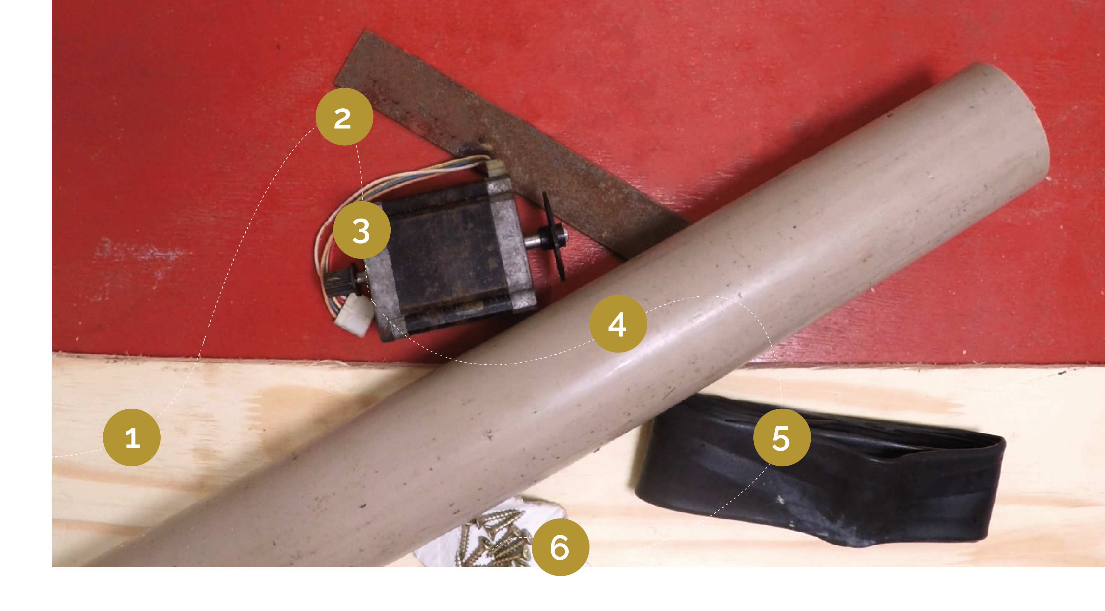
1- A wooden plank (minimum 10mm thick)
2- A piece of flat steel (minimum 2mm thick)
3- A stepper motor from a printer (with it's connectors)
4- A PVC tube (diameter between 55mm and 100mm;
wall thickness minimum 3mm)
5- A bicycle inner tube
6- Some wood screws
Electric circuit :
3- Stepper motor from a printer
8- A support made from plastic, to take the different system components
(you could e.g. use a flat part of the printer housing)
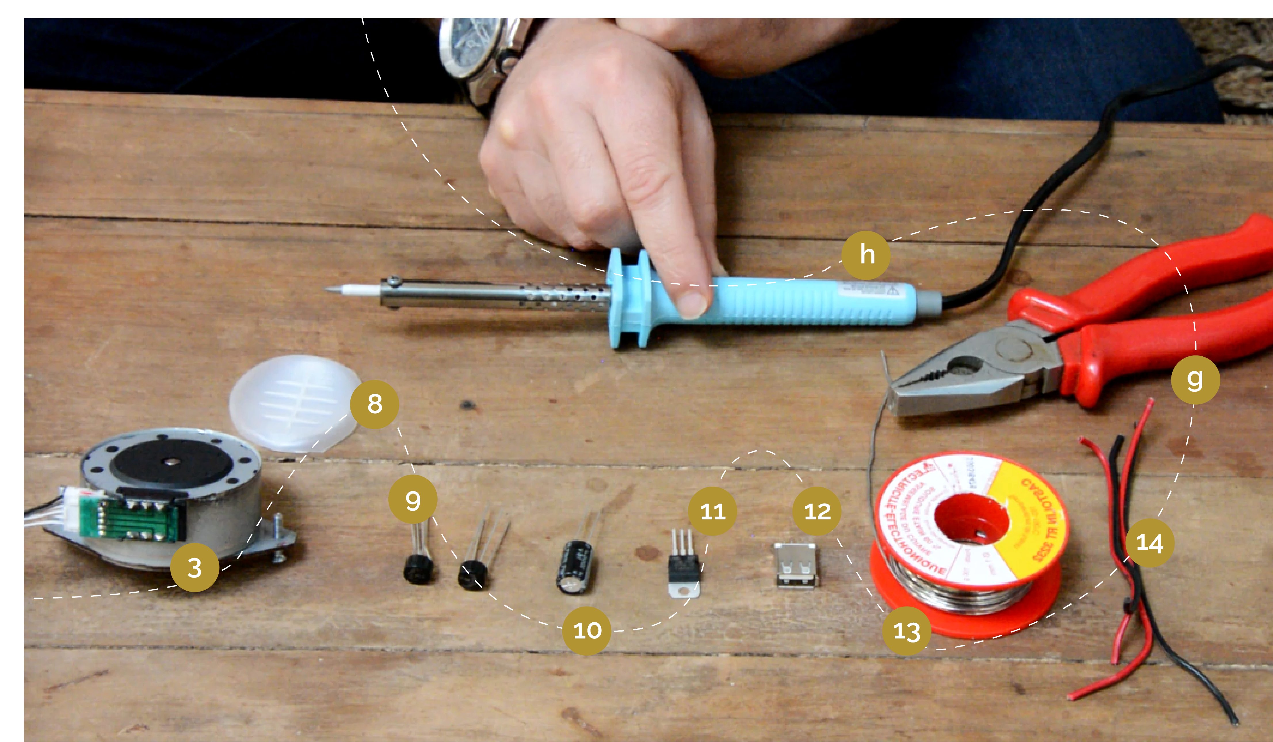
9- Two rectifier diodes or bridge rectifiers
10- One capacitor, 1000µF 16V
11- A voltage stabilizer LM7805 for fixing the voltage at 5V
or LM7812 for fixing the voltage at 12V
11'- Instead of the tension stabilizer you could also use a voltage amplifier
     or a DC/DC booster or even more advance it by supplying the USB connector
     with a voltage between 0,9 and 5 Volts.
12- An USB connector
13- solder
14- wire
Also take a look at global 3D model of this wind turbine after reading. [1]
Outils
Wind turbine
a - A vise
b - a saw for metal and wood
c - a ruler
d - a cordless screwdriver
e - a voltmeter
f - alligator clamps
- Arc wielding station
Electric circuit
g - wire cutting pliers
h - a soldering iron
Étape 1 - How it Works
This tutorial shows how to build a small wind turbine from old stepper motor
from an old printer or photocopier. It is able to e.g. charge a mobile phone.
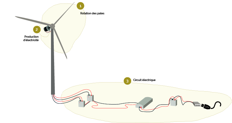
1 - Rotation of the blades
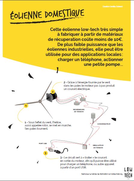
Powered by the wind, the propeller, also called rotor, starts to move. The blades rotate.
The rotor has 4 blades and is mounted on a mast in order to get more wind.
2 - Production of electricity
The rotor propels a stepper motor.
From the rotors rotation energy the stepper motor produces an alternating current (AC)
3 - Electric circuit
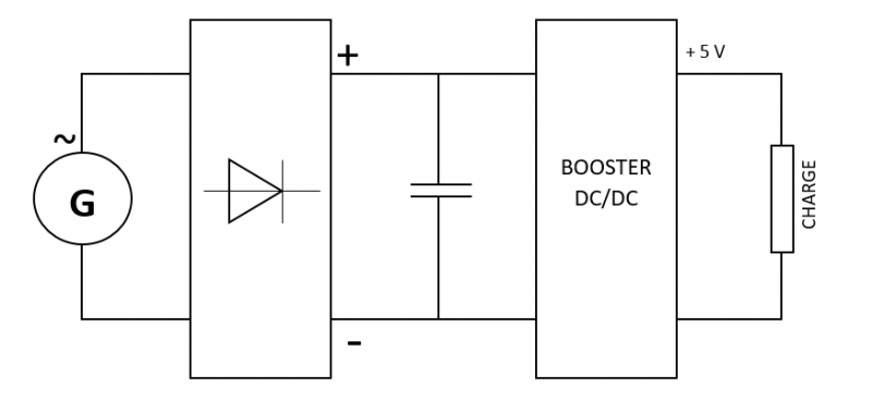
The circuit "handles" the alternating current from the motor output, so that it can be used to charge a mobile phone or another device via USB.
It consists of:
-The rectifiers, which "rectify" the tension from the motor output
in order to provide a direct current (DC).
- A capacitor which allows a continuous power supply,
although the wind doesn't blow at a constant speed.
A tension stabilizer which limits the tension produced by the motor at the desired voltage, e.g. 5V.
In order for the wind turbine to start rotating, a minimum wind speed of 10-15km/h is necessary.
Étape 2 - Steps Involved in Making the System
Wind turbine
1 - Preparing the motor
2 - Motor axis
3 - Preparing the rotor blades
4 - Aileron and base for rotor blades
5 - Assembly
Electric circuit
1 - Rectifiers
2 - Capacitors
3 - tension stabilizer
4 - Connecting the USB port
Motor protection
Étape 3 - Wind turbine - The motor
Choosing the motor
In general, the more steps the motor has, the lower the speed at constant voltage. Important technical data for the selection of the motor are : - The maximum or nominal voltage (measured in volts): Vmax - The current per phase (measured in amperes / phase): A/ph - Number of steps or step angle (measured in °)
For example, a stepper motor with an angle of 3.6° will have 360/3.6 = 100 steps, a 1.8° motor will have 360/1.8 : 200 steps . If you had to choose between two motors with identical characteristics (Vmax and A/ph), prefer the motor with the highest number of steps (here the 1.8° motor since it has 200 steps), it will require a lower rotation speed to deliver a satisfactory voltage.
The choice of motor will also be conditioned by the maximum voltage (Vmax). A motor characterized at 3V will deliver a much lower power than a motor characterized at 50V at the same rotation speed. Choose your motor (within the limit of the available choice) according to the desired application and the required power.
1 - Cut the 6 wires coming out of the stepper motor, strip and twist them.
From the two possible methods:
Method #1
In order to find out which of the 6 wires has the highest output voltage, all possible motor output torques must be tested and the two highest selected.
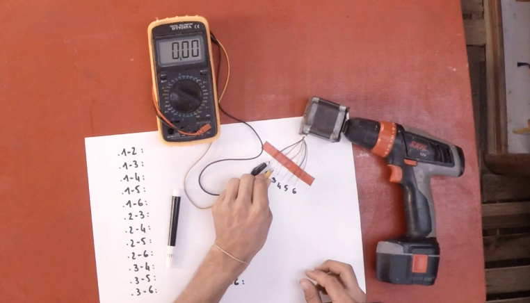
2 - Using a screwdriver, a voltmeter set to " AC " and alligator clips, test the pairs of wires. Note the tension for each pair. (picture 1)
3 - Select the two wire pairs with the highest output voltage (here 10V, this may vary depending on the motor). These will then be connected to the electrical circuit of the wind turbine.
* Tip: Mark with colored tape the two selected couples so they don't get mixed up with each other.
Method #2
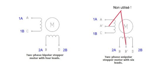
In fact, stepper motors are schematically made up of two or four coils:
(picture 2)
As described in the picture, in the case of a 6-wire we will not use the mid-point. In fact, we will accumulate two coils to make one and generate more tension.
From this point, it's very simple:
1) Just put your multimeter in ohm meter mode, or even better in contact detection mode (you know when it does "BBIIIIPPPPP !!" when the two probes are touching ).
2) The first step is to separate the two sets of wire for each coil.
For a 4-wire system, it's very simple: you take one wire on one probe, and with the other probe you touch the other wires. When there is one that goes "BBBIIIIIPPPPP!!" or the measured resistance becomes low (it depends on the motor but a wide range would be 1 to 50 ohms) you are good you have found your coil and by elimination the two remaining wires are for the other coil.
For a 6 wire it is hardly more complex: we apply the same method to determine the sets of 3 wires per spool. Then we switch to ohmeter mode and look for which pair of wires per coil gives the highest pllus resistance ==> bingo you have found the right wires for one coil, repeat the operation for the other and you are good.
Note: there are also 8 wires. In fact it is a 6-wire (so 4 coils) but with 4 independent coils (like a 4-wire so ...). So use the 4-wire method but more times.
Étape 4 - The Wind Turbine - Motor Axis
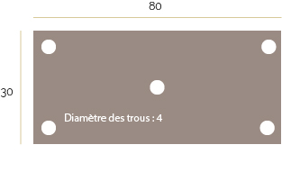
1 - Cutting a metal plate of 80x30 cm. Drill it with 5 holes of diameter 4mm.
* Tip: You can use figure 1 above to cut and drill the plate.
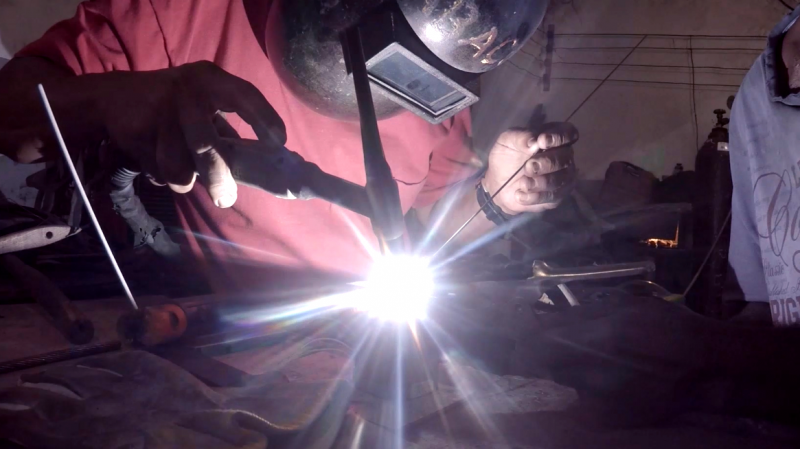
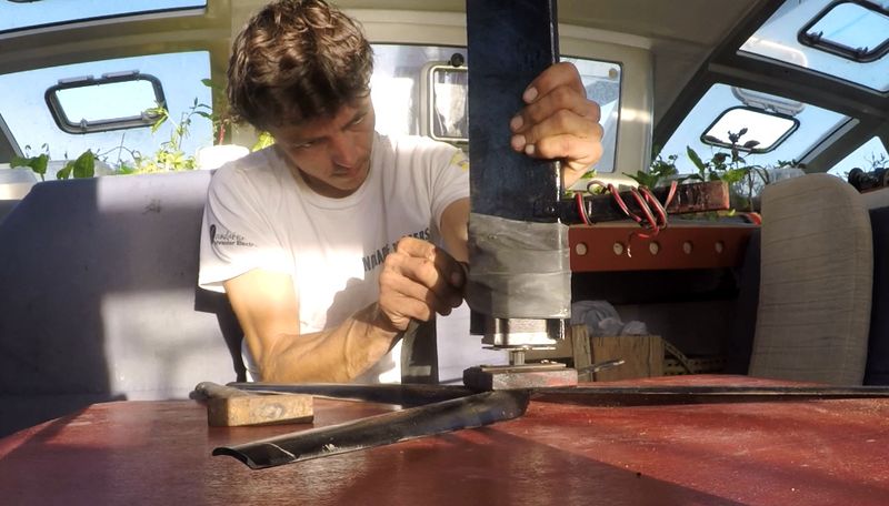
2 - Weld the motor shaft to the central hole of the metal plate (picture 2).
Étape 5 - The Wind Turbine - Blade Preparation
From the formula linking the wind speed, a given surface and the power of the wind on this surface :
This formula can be used to calculate the length of the blades of the wind turbine:
Where:
- L = blade length in m
- P = characteristic power of the motor in W
- V = wind speed in m/s (depending on location)
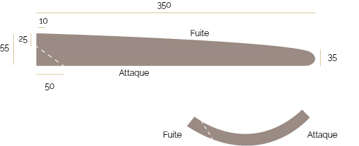
Under normal conditions, the length of the blade should be 35 cm.
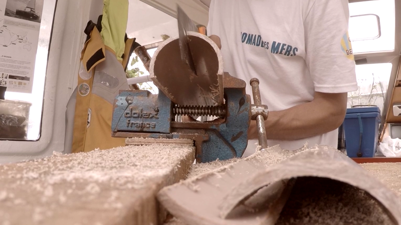
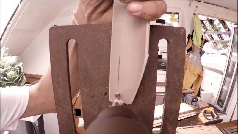
1 - Draw and cut the blades in a PVC tube. (picture 3).
* Tip: You can help yourself from the diagram 2 above to draw the shape of the blades.
Figure 3 shows the cutting direction.
2 - Sand the edges of each of the blades: the leading edge must be rounded, and the trailing edge sharpened.
3 - Drill the blades: the drilling is carried out as close as possible to the trailing edge so that the latter can be fixed flat on the plate that carries the blades. (image 4)
Your blades are ready!
Étape 6 - The Wind Turbine - Fins and Blade Bases
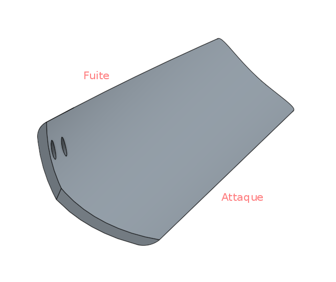
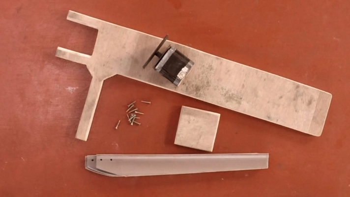
1 - In a wooden board, draw and cut out the fin. (image 5)
* Tip: You can use figure 3 above to draw the shape of the fin.
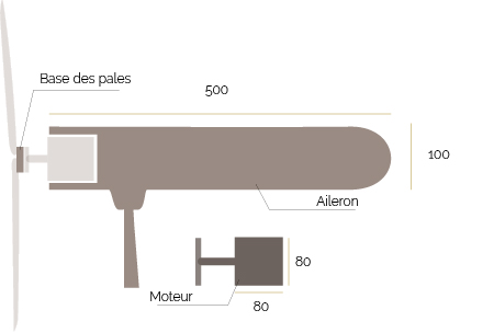
2 - In the same board, cut out a square the size of your engine (here 80x80cm) which will be used to accommodate the blades previously cut out in order to join them together. (diagram 3 - base of the blades).
3 - On the aileron, mark the location of the motor so that it can be forced into the shape. (diagram 3 - motor)
* Note: The dimensions of this part depend on the size of your motor.
4 - Sand the edges of the aileron for better aerodynamics and better rendering. (frame 5)
Étape 7 - The Wind Turbine - Assembly
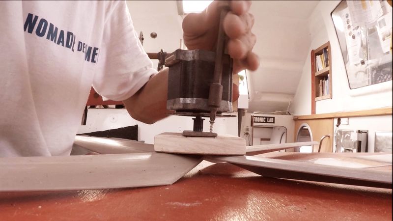
1 - Screw the blades (cut out in step 3) to their base (cut out in step 4).
2 - Screw the base of the blades to the metal plate. Use the holes drilled in the metal plate in step 2. (image 6).
3 - Check that there is the same angle between each of the blades.
Étape 8 - The electrical circuit - Rectifiers
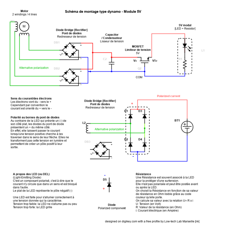
The electrical circuit is as shown in "Figure 4".
At the output of the engine, we get alternating current (AC). However, to charge a battery or light a lamp, it is necessary to have direct current (DC). Two rectifiers are used to transform alternating current into direct current: they "rectify" the voltage at the output of the motor.
Each rectifier has 4 legs: The two central legs are the alternating poles of the capacitor. The two outer legs are the positive and negative poles of the capacitor.
* Tip: on the rectifier head each of these 4 poles are marked
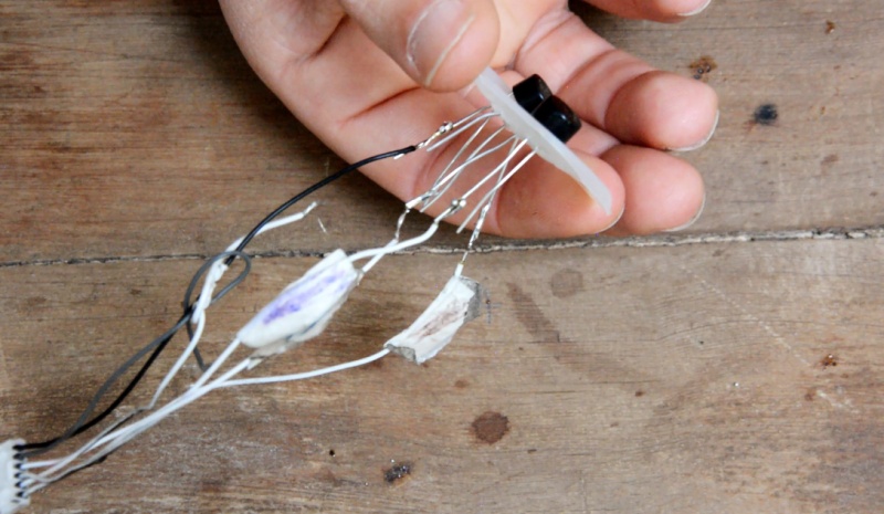
1 - Solder the stepper motor voltage outputs (previously selected) to the alternating inputs of each rectifier: the first torque with the alternating poles of the first rectifier, and the second torque with the alternating poles of the second rectifier.(image 7).
* Tip: It is possible to use heat shrink tubing to cover the connections to protect the system.
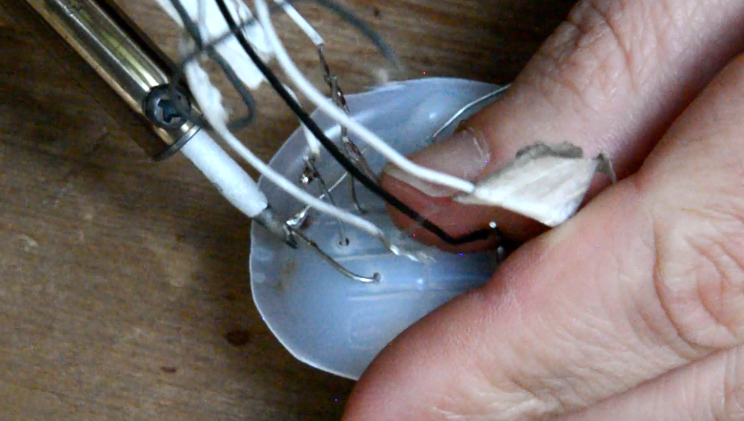
2 - Solder the negative outputs of the two rectifiers together, then solder the positive outputs of the two rectifiers together. "(picture 8).
Étape 9 - The electrical circuit - Capacitor
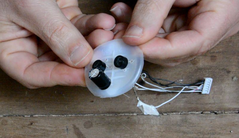
The energy supplied by the wind turbine is not constant because the wind speed is constantly changing. The overload must therefore be temporarily stored in order to to be able to redistribute it consistently. A capacitor is used for this purpose.
The capacitor is a polarized component: - the positive terminal is the longest leg - the negative terminal is the shortest leg
* Tip: It is also possible to refer to the "-" symbol written on the minus pole.
1 - Solder the negative poles together and then the positive poles together at the rectifier output. (image 9).
* Tip: If the legs of your components are too short to weld together, you can connect them with electrical wires.
Étape 10 - The electrical circuit - Voltage regulator or voltage booster
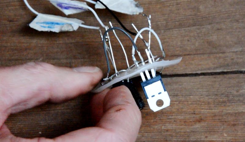
The voltage regulator makes it possible to recover a 5V output current.
*Note: Each controller is different, if you want a 12V output, for example, buy your controller accordingly. Here to connect a USB port we'll use a 5V one.
The voltage regulator has 3 different rods : - 1 entry - 1 common - 1 exit
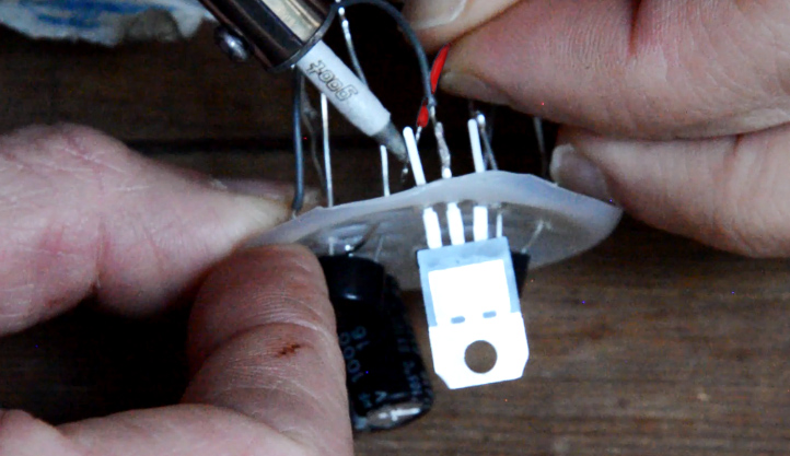
1 - Solder the negative pole of the capacitor with the common of the voltage regulator. Solder the plus of the capacitor to the input of the voltage regulator.(image 10)
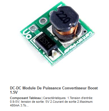
Alternative: use a voltage booster that will provide an output voltage of 5V (USB) with an input voltage ranging from 0.9 to 5V.
Étape 11 - The electrical circuit - Connecting the USB port
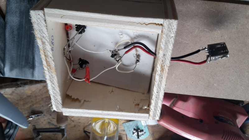
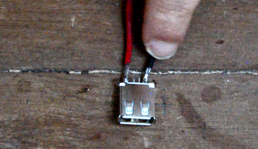
When you place your connector on a table with the plastic tab facing up, the right tab is your positive terminal, and the left tab is your negative terminal.
1 - Solder a red wire to the positive terminal and a black wire to the negative terminal. These will be the output wires of your wind turbine, to which you can connect a battery, a light bulb, etc, and in this case a USB port. (picture 11)
2 - Solder the red wire to the regulator output and the black wire to the regulator common. (image 12).
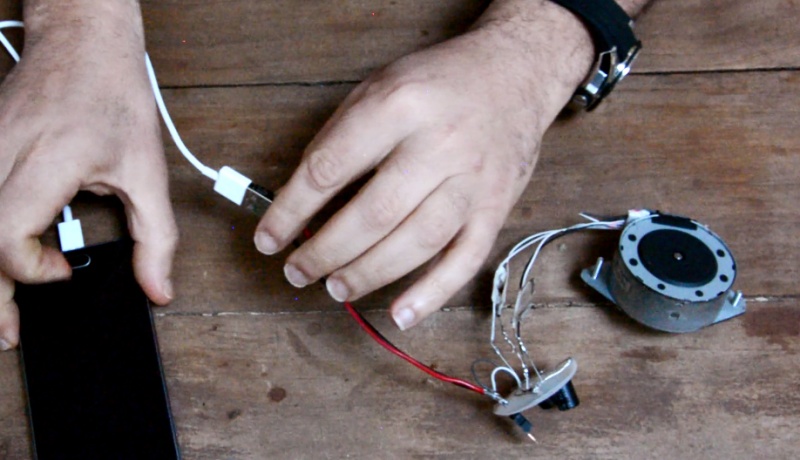
Your circuit's ready to go. You can connect a telephone to it, provided there is wind of course.(picture 13)'
Étape 12 - Motor protection
Cover the engine and the inner tube electrical circuit: this will protect them from rain or sea spray. (picture 14)
Étape 13 - Use
Connect a mobile phone or other device with a USB connection to the electrical circuit and let it charge for a few hours. In an average wind, allow 5 hours of charging time for a phone battery.
Étape 14 -
Got two minutes? Whether or not you would like to do this low-tech, your answer to this form would help us improve our tutorials. Thank you in advance for your help!
As all the work of the Low-tech Lab, this tutorial is participative. Please do not hesitate to add the modifications which seem important to you, and to share your achievements in comments.
Étape 15 - Contenu pédagogique à télécharger
Vous pouvez télécharger une fiche pédagogique créée par le Low-tech Lab dans la partie "Fichiers" du tutoriel (onglet au niveau de la section "Outils-Matériaux").
Notes et références
Feel free to comment, share, and enhance the tutorial with useful information to improve it.
FIND THE SKAVENJY TUTORIAL, inspired by this model: Click here
Find detailed information on self-built wind turbines on the website www.kdwindturbines.nl. Many reports are available, and the document Reports for self-study provides an overview of the reports recommended for the study the different technical parts of a wind turbine. For more information about different types of safety systems which turn the rotor out of the wind in case of high winds, have a look on the public report KD 485.
Published


 Français
 English
 Deutsch
 Español
 Italiano
 Português