(Page créée avec « Insert the rod in the 5mm hole, with a bit of thread lock. ») |
(Page créée avec « [https://www.youtube.com/watch?v=HZNX5r4G-cs]Watching this video will help you to understand the strain disassembly : https://www.youtube.com/watch?v=HZNX5r4G-cs ») |
||
| Ligne 255 : | Ligne 255 : | ||
Insert the rod in the 5mm hole, with a bit of thread lock. | Insert the rod in the 5mm hole, with a bit of thread lock. | ||
| − | [https://www.youtube.com/watch?v=HZNX5r4G-cs] | + | [https://www.youtube.com/watch?v=HZNX5r4G-cs]Watching this video will help you to understand the strain disassembly : https://www.youtube.com/watch?v=HZNX5r4G-cs |
'''<u>Deuxième technique à l'aide d'un clapet anti-retour (image 3):</u>''' | '''<u>Deuxième technique à l'aide d'un clapet anti-retour (image 3):</u>''' | ||
Version du 22 avril 2020 à 09:42
Description
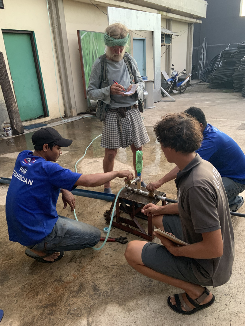
The purpose of this tutorial is to facilitate the understanding, design, manufacture and installation of a water elevation system called "Ram pump". This technology was documented during a stopover of the Sea Nomad in the Philippines, on the island of Negros. The NGO "Alternative Indigenous Development Foundation (AIFDI)", based in the city of Bacolod since 1991, helps more than 160 rural communities meet their water needs by installing hydraulic rams throughout the archipelago. The ram pump presented in this tutorial is a different version from the one used by the AIFDI because it is more accessible.
Sommaire
Sommaire
- 1 Description
- 2 Sommaire
- 3 Introduction
- 4 What is the purpose of a ram pump?
- 5 Video d'introduction
- 6 Étape 1 - How does a ram pump work?
- 7 Étape 2 - Evaluate a site and size the ram pump
- 8 Étape 3 - Choose your type of installation
- 9 Étape 4 - Air chamber
- 10 Étape 5 - Primary valve (or impact valve)
- 11 Étape 6 - Assemblage
- 12 Étape 7 - Support
- 13 Étape 8 - Mise en fonctionnement
- 14 Notes et références
- 15 Commentaires
Introduction
This tutorial was initiated by http://lowtechlab.org/wiki/Utilisateur:Basile_Sans%C3%A9au
The hydraulic ram system was invented in 1797 by Joseph-Michel Montgolfier, the man who built the first hot air balloon in 1782 with his brother, Jacques-Étienne. He was immediately criticized by his contemporaries who associated him with the theories of perpetual movement, which were considered heresies at the time.
It was not until 1857 that a patent was filed by Ernest Sylvain Bollée, which improved and made Montgolfier's invention a reality.
Since then, it has been widely used in the French and European countryside, and is now established in America and Africa in regions where fuel supplies are difficult or expensive.
What is the purpose of a ram pump?
The hydraulic ram pump is a water elevation system whose operation depends solely on the driving force of the water, without any other external intervention. In concrete terms, this makes possible to pump water from a source (river, lake, stream) and use it higher to irrigate crops, water livestock or for any other domestic use.
The ram pump has several advantages:
- It is relatively inexpensive
- It operates fully automatically, without electricity, over a long period of time, some rams have been operating for several decades
- It requires no lubrication, no maintenance other than cleanliness care
- Repairs are infrequent, only necessary due to the inevitable wear and tear of moving parts
- It can be adapted to almost any size to suit the desired flow rates and heights
Youtube
Matériaux
Do not use plastic material for the ram, whether valves or flaps, as they will wear out very quickly during operation..
To buy:
-vanne of 26/34mm
-1 elbow of 26/34
-3 male plumbing nipples in 26/34
-1 Tee of 26/34
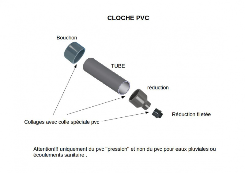
-1 strainer in 26/34 or a plastic check valve inside (see step 5)
-1 check valve in 26/34 with stainless steel/brass interior
-2 valves in 20/27 or 1 valve with drain valve
-1 cross of 20/27
-1 reduction from 26/34 to 20/27
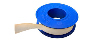
-1 or 2 teflon rollers for sealing the entire assembly
-Thread lock for fixing the threaded rod
-4 rods with wing nuts
- a dozen washers with an internal diameter of 6mm
-2 nuts for M5 threaded rod
To be recovered:
-1 extinguisher of 7 or 9 litres
-1 inner tube or other rubber to make a seal
- Nails
- 1 wooden board
-flat iron 20 or 30 mm wide, about 60 cm
-a torch (according to step 5)
Outils
- a plier
- a claw to open the strainer
- Scissors
- Hammer
- -a drill bit (here 6, 7mm)
- a tap ( here M5)
Étape 1 - How does a ram pump work?
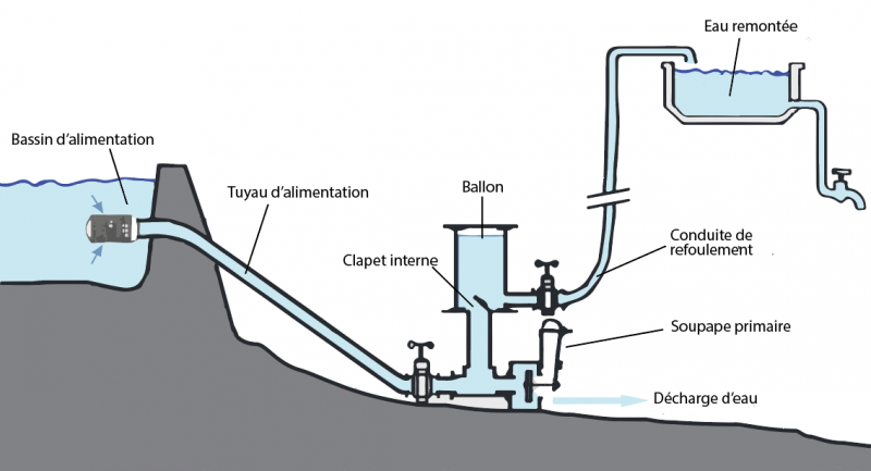
- When priming, water flowing into the inlet line flows into the weir through the primary valve.
- The acceleration of the water causes the primary valve to close suddenly.
- The water column is suddenly braked and generates an overpressure in the pump casing (water hammer), which opens the internal valve.
- Under the effect of this overpressure, water flows into the balloon (and the discharge duct), compressing the air volume until the pressures are balanced.
- The pressure reversal closes the internal valve.
- The water trapped under pressure in the balloon empties into the discharge line until the pressures are balanced (determined by the height of the pipe).
- The closing of the internal valve has caused the pressure to drop, so the primary valve opens again. A new cycle begins....
Without accident, this process is perpetually renewed as long as it is supplied with water.
Étape 2 - Evaluate a site and size the ram pump
First of all, it is necessary to find surface water that continuously flows on a sufficiently steep slope (about 10% minimum). If it's a dam or lake, make sure that there are positions below.
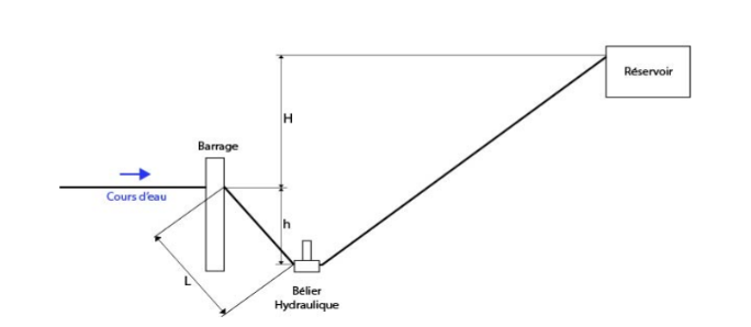
To evaluate a site, 4 parameters have to be estimated (as shown on the scheme) :
- q water flow
- H lift height
- L driving line lenght
- h fall height
Concerning the water flow, it it not necessary to be really precise, an average value would be enough to size the system. Several techniques are available, depending on your material and time : see Water flow estimation"
The lift height corresponds to the height difference between the pump height and the water reservoir. Concretely you should decide where you want the water to arrive, and measure the height difference between this point and the water source (in average). This measure will be precised later in the process. Slope measuring can be done with this website https://www.geoportail.gouv.fr/carte : Place GPS coordinates on the map, and use the function "asymetric profile". This correspond to a curve showing the elevation depending on the distance (in m).
The driving line lenght and the fall height are directly related to the river or lake slope. In this case as well, it would be interesting to establish an asymetric profile in order to take distances and elevation gradients into account.
Once the parameters of the site are identified, we will size the pump in order to retrieve the needed flow and a minimal installation coast (the smaller the pump is, the cheaper it will be).
Determine L, H and h:
General Formula: q=((h*Q)/(h + H))0.70
Where 0.70 is the pump efficiency and Q the arrival flow.
Concretely, you will need:
- H/10<h<H/2
- 3H <L<15H
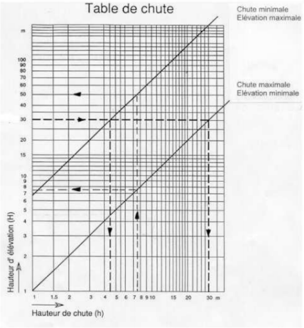
You can also use a fall diagram as shown on the picture to determine H and h.
Sizing of the pump:
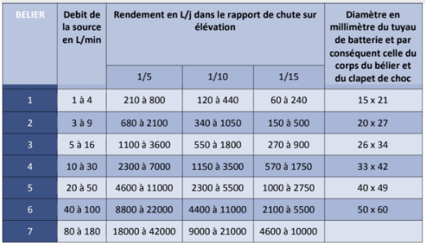
To size the pump itself, you have to chose the needed arrival flow. One of the easiest ways to do that is to use the provided table, that gives the final pipe size according to the source flow, the elevation ratio h/H and the final flow.
Using the table, you can proceed as follows:
- Choose the final flow, corresponding to you water needs
- Find the corresponding number in the table according to the elevation ratios of your site
- Do not hesitate to oversize the system in case of doubt
- Verify that you water flow is higher than indicated in the table
- On the same table line, you can read the relevant pump sizing for you situation
You obtain the battery pipe (or driving line) diameter D, which is the same for all other components of the pump.
For example: 26x34 to an internal diamter of 26mm and an external diameter of 34mm| Millimeters (mm) | Inches |
| 15x21 | 1/2 |
| 20x27 | 3/4 |
| 26x34 | 1 |
| 33x42 | 1 1/4 |
| 40x49 | 1 1/2 |
| 50x60 | 2 |
All pump components will therefore be of the same dimension, except for the outlet pipe (or delivery pipe) whose diameter D' will be half of the driving line D. D'=D/2
Étape 3 - Choose your type of installation
When building a ram pump, 2 different configurations exist that will play a role on the pump efficiency. They concern positions of the primary valve, the internal valve and the air chamber.
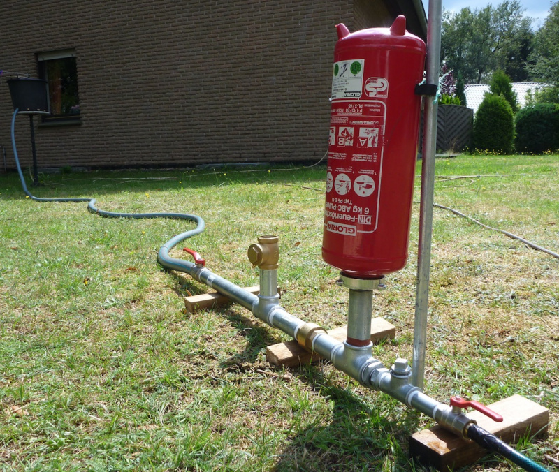
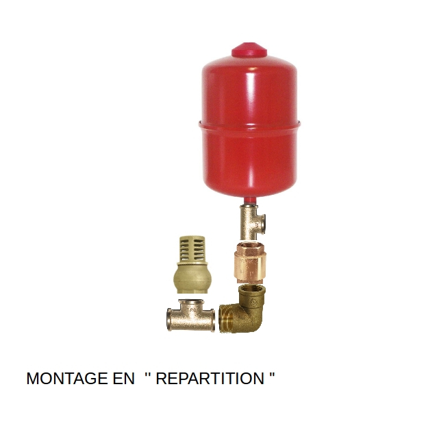
Repartition assembly (image 1):
In this case, the primary valve is before the air chamber. This position can make the pump look rather flat, as shown in the first picture of this page. Some sources state that this system can reach 20% higher performance than the other, but we have not been able to prove it yet.
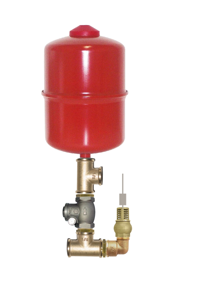
In butting assembly (image 2):
We will describe this system in the tutorial, as it is more widely used. The pump will look more vertical.
Étape 4 - Air chamber
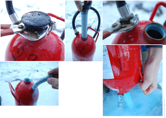
To disassemble the extinguisher, you should unscrew the mouthpiece with a wrench and take out the CO2 cartridge it contains.
Then, take out the plastic pipe and the lance.
The outer part is normalised 20x27 and will be screwed to the pump.
To obtain a functional air chamber, you should also empty it from the powder and clean the inside of the extinguisher.
The lance hole should be stuck with something that resists pressure ! If you don' find a lid, you can weld a round metallic part on it.
Souder une pièce ronde ou trouver un bouchon pour fermer le trou de la lance. Il faut que ça puisse tenir la pression.
Étape 5 - Primary valve (or impact valve)
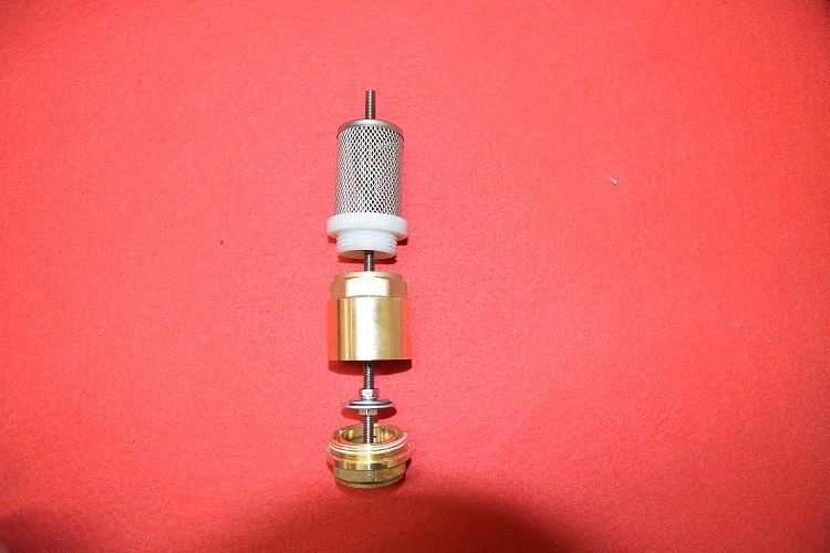
First technique using a strainer (image 1):
This version is the sturdiest, but will be a bit harder to build
Firstly, disassemble the strainer using a claw clamp.
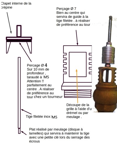
One the valve is recovered, drill a hole is the center with a 4mm drill. You might ask a turner in his workshop.
Tap at 5mm.
Drill a 6 or 7 mm hole at the top center of the strainer.
Insert the rod in the 5mm hole, with a bit of thread lock.
[1]Watching this video will help you to understand the strain disassembly : https://www.youtube.com/watch?v=HZNX5r4G-cs
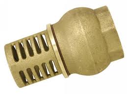
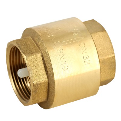
Deuxième technique à l'aide d'un clapet anti-retour (image 3):
Cette technique est moins solide mais plus accessible car ce type de clapet en plastique se trouve dans tous les magasins en france.
Pour ouvrir le clapet anti-retour:
-placer des raccords mâles de chaque côté pour éviter de l'abîmer pendant la manipulation
- Distinguer une ligne (très fine) séparant les deux partie du clapet
- Chauffer à l'aide d'un chalumeau au niveau de cette ligne pour faire fondre la colle à l'intérieur (ne pas trop chauffer non plus).
- Dévisser la clapet (à l'aide d'une pince à griffe et d 'un étau par exemple)
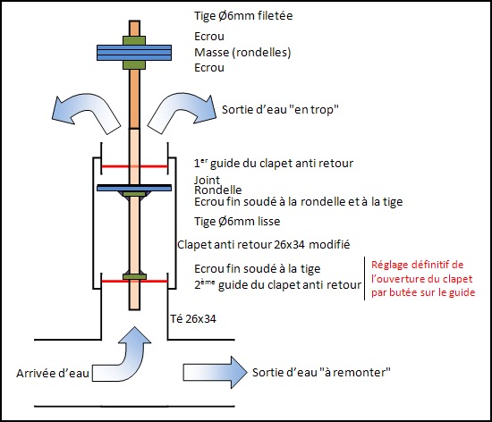
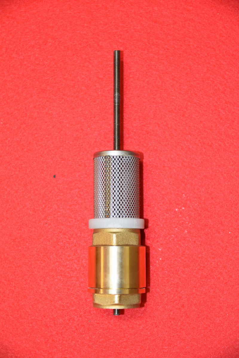
Il suffit ensuite d'enlever le clapet en plastique contenu à l'intérieur et de le remplacer par une rondelle, des écrous et une tige filetée comme sur la quatrième image.
Étape 6 - Assemblage
Avant d'assembler le système, il recouvrir les filetages de téflon ou de tout autre moyen permettant d'assurer l'étanchéité.
Voici une vidéo explicative pour la pose du téflon.
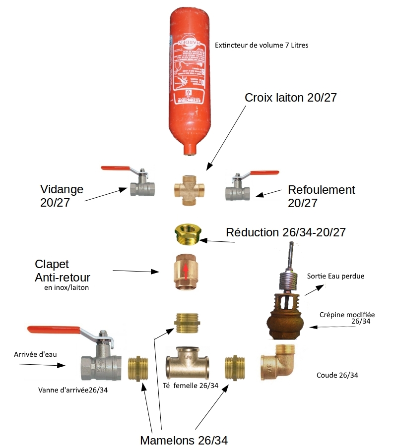
Il suffit ensuite d'assembler le bélier selon le schéma ci-contre.
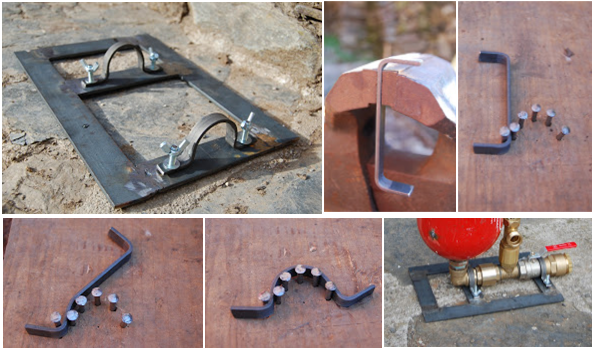
Étape 7 - Support
Pour choisir un support il faut prendre en compte la taille du dispositif et en particulier de la cloche à air car c'est elle qui risque de faire basculer l'ensemble. Le socle peut être en bois ou en métal mais pour des bélier sensés résister dans le temps l'idéal est de couler une dalle de béton pour fixer l'ensemble.
Découper les fers plats en fonction des longueurs désirées.
Fabriquer 2 ou 3 pièces en arc avec la méthode des clous (en traçant l'arc au diamètre du raccord choisi pour la fixation).
Percer les pièces en arc et le socle aux bons endroits afin d'obtenir un serrage conséquent mais pas démesuré (pour ne pas abîmer les conduites).
Fixer les pièces en arc au socle avec le bélier grâce à des tige filetées et des écrous papillon.
Étape 8 - Mise en fonctionnement
Tout d'abord, placer le bélier dans un endroit plat et régulier, s'aider d'un niveau si nécessaire. Installer en suite la conduite de chute ainsi que celle de refoulement et effectuer les branchements (sans oublier le téflon).
Initialement, le bélier est vide d'eau et toutes les vannes sont fermées. On commence par ouvrir un peu la vanne de refoulement vers la citerne, puis en totalité celle d'arrivée d'eau. Normalement l'eau va pousser sur le clapet de choc et le mettre en marche.
S'il n'est pas encore en mouvement, il est utile de l'actionner plusieurs fois à la main afin d'avoir suffisamment de contre-pression dans la conduite de refoulement pour lancer le système. Il est possible que ça ne marche pas si le poids des rondelles est trop grand ou si le réglage de la course du clapet n'est pas adapté, c'est pourquoi ce modèle vous permet de faire ces réglages en changeant la position du premier écrou et le nombre de rondelles. Le réglage impactera aussi sur la quantité d'eau remontée par rapport à celle perdue.
Vous devrez vidanger régulièrement le bélier. En effet, le principe de fonctionnement implique qu'il doit y avoir toujours de l'air sous pression, poussée par l'eau, dans la cloche, or cet air se videra au fur et à mesure. Il faudra donc couper la vanne d'arrivée et de refoulement, ouvrir celle de vidange et réamorcer comme initialement.
Notes et références
- Permatheque
- PDF sur la remontée d'eau, les conduites, les débits...
- http://www.belier-inox.fr/fabriquez-votre-belier-p867652
- http://www.pearltrees.com/apfeltheo/construction/id12619255#item125024933
- http://www.regispetit.fr/bel_pra.htm#pra7
- http://www.cluber.inter-systeme.ca/belier.html
- https://sites.google.com/site/fabricationdunepompeabelier/
- https://www.humanosphere.info/2014/07/comment-construire-une-pompe-a-eau-qui-fonctionne-sans-electricite/
Published
 Français
 English
 Deutsch
 Español
 Italiano
 Português