(Page créée avec « ====<u>Building the mold</u> :==== ») |
(Mise à jour pour être en accord avec la nouvelle version de la source de la page) |
||
| (59 révisions intermédiaires par 2 utilisateurs non affichées) | |||
| Ligne 6 : | Ligne 6 : | ||
|Type=Tutorial | |Type=Tutorial | ||
|Difficulty=Easy | |Difficulty=Easy | ||
| − | |Duration= | + | |Duration=3 |
|Duration-type=hour(s) | |Duration-type=hour(s) | ||
|Cost=10 | |Cost=10 | ||
|Currency=EUR (€) | |Currency=EUR (€) | ||
| − | |Tags=lampe, solaire, batterie lithium recyclées, récupération, batterie ordinateur portable, recyclage, cellules lithium usagées, NomadeDesMers, nomade des mers, | + | |Tags=lampe, solaire, batterie lithium recyclées, récupération, batterie ordinateur portable, recyclage, cellules lithium usagées, NomadeDesMers, nomade des mers, liter of light |
}} | }} | ||
{{Introduction | {{Introduction | ||
| − | |Introduction=Lithium is a natural resource whose stocks are increasingly used for electric cars, telephones, and computers. This resource is gradually being depleted over time. Its increased use in battery manufacturing is mainly due to its ability to store more energy than nickel and cadmium. The replacement of electrical and electronic equipment is accelerating and it is becoming an increasingly important source of waste. France currently produces 14kg to 24kg of electronic waste per inhabitant per year. This rate increases by about 4% per year. In 2009, only 32% of young French people aged between 18 and 34 years old, have once recycled their electronic waste. In the same year 2009, according to Eco-systèmes, from January to September 2009, 113,000 tonnes of CO2 were avoided through the recycling of 193,000 tonnes of DEEE | + | |Introduction=Lithium is a natural resource whose stocks are increasingly used for electric cars, telephones, and computers. This resource is gradually being depleted over time. Its increased use in battery manufacturing is mainly due to its ability to store more energy than nickel and cadmium. The replacement of electrical and electronic equipment is accelerating and it is becoming an increasingly important source of waste. France currently produces 14kg to 24kg of electronic waste per inhabitant per year. This rate increases by about 4% per year. In 2009, only 32% of young French people aged between 18 and 34 years old, have once recycled their electronic waste. In the same year 2009, according to Eco-systèmes, from January to September 2009, 113,000 tonnes of CO2 were avoided through the recycling of 193,000 tonnes of DEEE. |
| − | However, this waste has a high recycling potential. In particular, lithium | + | However, this waste has a high recycling potential. In particular, the lithium in the cells of computer batteries can be recovered and reused. When a computer battery does not work anymore, it is because one or more cells are defective, but some remain in good condition and can be reused. From these cells it is possible to create a separate battery, which can be used to power an electric drill, recharge your phone or be connected to a solar panel to operate a lamp. By associating several cells it is also possible to form batteries of storage of more important device. |
| − | |||
| − | |||
| + | The design of this lamp is inspired by a system documented by the Nomade des Mers expedition on the island of Luzong in the northern Philippines. The association Liter of Light has been installing similar systems in villages without electricity for nearly 6 years, also organizing training to allow villagers to repair the lamps independently (already 500 000 lamps installed). | ||
(Turn on subtitles for the video, you will have every details !) | (Turn on subtitles for the video, you will have every details !) | ||
| Ligne 37 : | Ligne 36 : | ||
|Step_Picture_04_annotation={"version":"2.4.6","objects":[{"type":"image","version":"2.4.6","originX":"left","originY":"top","left":-236.16,"top":-195.49,"width":800,"height":533,"fill":"rgb(0,0,0)","stroke":null,"strokeWidth":0,"strokeDashArray":null,"strokeLineCap":"butt","strokeDashOffset":0,"strokeLineJoin":"miter","strokeMiterLimit":4,"scaleX":1.4,"scaleY":1.4,"angle":0,"flipX":false,"flipY":false,"opacity":1,"shadow":null,"visible":true,"clipTo":null,"backgroundColor":"","fillRule":"nonzero","paintFirst":"fill","globalCompositeOperation":"source-over","transformMatrix":null,"skewX":0,"skewY":0,"crossOrigin":"","cropX":0,"cropY":0,"src":"https://lowtechlab.org/w/images/thumb/c/c9/Lampe_solaire_%C3%A0_batteries_lithium_r%C3%A9cup%C3%A9r%C3%A9es_59955761_1290942564386726_3445616798588731392_n.jpg/800px-Lampe_solaire_%C3%A0_batteries_lithium_r%C3%A9cup%C3%A9r%C3%A9es_59955761_1290942564386726_3445616798588731392_n.jpg","filters":[]}],"height":450,"width":600} | |Step_Picture_04_annotation={"version":"2.4.6","objects":[{"type":"image","version":"2.4.6","originX":"left","originY":"top","left":-236.16,"top":-195.49,"width":800,"height":533,"fill":"rgb(0,0,0)","stroke":null,"strokeWidth":0,"strokeDashArray":null,"strokeLineCap":"butt","strokeDashOffset":0,"strokeLineJoin":"miter","strokeMiterLimit":4,"scaleX":1.4,"scaleY":1.4,"angle":0,"flipX":false,"flipY":false,"opacity":1,"shadow":null,"visible":true,"clipTo":null,"backgroundColor":"","fillRule":"nonzero","paintFirst":"fill","globalCompositeOperation":"source-over","transformMatrix":null,"skewX":0,"skewY":0,"crossOrigin":"","cropX":0,"cropY":0,"src":"https://lowtechlab.org/w/images/thumb/c/c9/Lampe_solaire_%C3%A0_batteries_lithium_r%C3%A9cup%C3%A9r%C3%A9es_59955761_1290942564386726_3445616798588731392_n.jpg/800px-Lampe_solaire_%C3%A0_batteries_lithium_r%C3%A9cup%C3%A9r%C3%A9es_59955761_1290942564386726_3445616798588731392_n.jpg","filters":[]}],"height":450,"width":600} | ||
|Step_Picture_05=Lampe_solaire_à_batteries_lithium_récupérées_60045424_801990190183660_4606583588689805312_n.jpg | |Step_Picture_05=Lampe_solaire_à_batteries_lithium_récupérées_60045424_801990190183660_4606583588689805312_n.jpg | ||
| − | |Material=*Used laptop battery | + | |Material=*Used laptop battery (Li-ion 18650) |
| − | *Li-ion 18600 | + | *Li-ion 18600 battery holders |
*Solar panel 5V-6V / 1-3W | *Solar panel 5V-6V / 1-3W | ||
| Ligne 47 : | Ligne 46 : | ||
*DC/DC tension converter [https://www.addicore.com/MT3608-Boost-Converter-p/ad300.htm DC/DC booster] MT3608 (electrical component that will transform the 3.7 V of the batteries into 5 V) | *DC/DC tension converter [https://www.addicore.com/MT3608-Boost-Converter-p/ad300.htm DC/DC booster] MT3608 (electrical component that will transform the 3.7 V of the batteries into 5 V) | ||
| − | *High power LED Lamp (ex : [https://www.ebay.com/b/3-W-LED-Light-Bulbs/20706/bn_7115563288 LED boutons 3W] ) | + | *High power LED Lamp (ex : [https://www.ebay.com/b/3-W-LED-Light-Bulbs/20706/bn_7115563288 LED boutons 3W] max) |
* Switch (to open the circuit and cut off the light) | * Switch (to open the circuit and cut off the light) | ||
| Ligne 146 : | Ligne 145 : | ||
''' Voltage measure:''' | ''' Voltage measure:''' | ||
| + | <div class="mw-translate-fuzzy"> | ||
We start by measuring the voltage of each cells in order to check if they are working properly. Every cells that have a voltage lower than 3V will not be able to be used in this project and should be recycle. | We start by measuring the voltage of each cells in order to check if they are working properly. Every cells that have a voltage lower than 3V will not be able to be used in this project and should be recycle. | ||
| + | </div> | ||
*Using a multimeter, in DC mode, measure each cells and check the one that are usable ofr the project. | *Using a multimeter, in DC mode, measure each cells and check the one that are usable ofr the project. | ||
| Ligne 154 : | Ligne 155 : | ||
''' Measure the capacity :''' | ''' Measure the capacity :''' | ||
| + | <div class="mw-translate-fuzzy"> | ||
To measure the capacity of a cell, we have to charge it to the maximum and then discharge it. | To measure the capacity of a cell, we have to charge it to the maximum and then discharge it. | ||
Those cells are lithium based, and need a specific charge and discharge system, ususally the maximal charge is 4,2 V and the minimum is 3V. | Those cells are lithium based, and need a specific charge and discharge system, ususally the maximal charge is 4,2 V and the minimum is 3V. | ||
Going over those limits will damage the cell. | Going over those limits will damage the cell. | ||
| + | </div> | ||
*Use a PowerBank : it will alow you to charge many cells at once with a USB port. | *Use a PowerBank : it will alow you to charge many cells at once with a USB port. | ||
| Ligne 164 : | Ligne 167 : | ||
*The cells will be charge at their maximum (4,2V), now we have to discharge them. | *The cells will be charge at their maximum (4,2V), now we have to discharge them. | ||
| + | <div class="mw-translate-fuzzy"> | ||
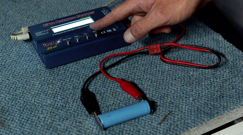
*You should use an Imax B6 : a tool that allow to discharge the cells and check their capacity. | *You should use an Imax B6 : a tool that allow to discharge the cells and check their capacity. | ||
| + | </div> | ||
*How to use the tool : | *How to use the tool : | ||
| Ligne 170 : | Ligne 175 : | ||
*the voltage : it will ask you which type of cells you would like to check, you should choose the lithium one. It will automatically regulate the discharge at 3V minimum. | *the voltage : it will ask you which type of cells you would like to check, you should choose the lithium one. It will automatically regulate the discharge at 3V minimum. | ||
| + | <div class="mw-translate-fuzzy"> | ||
*the intensity : set to 1A in order to have a quick and secure discharge. In this condition, the discharge should take between 1 hour and 1 hour and half. | *the intensity : set to 1A in order to have a quick and secure discharge. In this condition, the discharge should take between 1 hour and 1 hour and half. | ||
| + | </div> | ||
*Connect the magnet to the crocodile clips, then connect to the cell, the magnet help to let the current pass through the Imax B6 to the cells. ''(image 4)'' | *Connect the magnet to the crocodile clips, then connect to the cell, the magnet help to let the current pass through the Imax B6 to the cells. ''(image 4)'' | ||
| Ligne 196 : | Ligne 203 : | ||
* Weld the red wire (positive) with the IN+ input of the charge regulator and the black wire (negative) with the IN- input ''(image 5)''. | * Weld the red wire (positive) with the IN+ input of the charge regulator and the black wire (negative) with the IN- input ''(image 5)''. | ||
| + | {{Idea|1= If you are a beginner, you can go to this how-to, which explains the principles of the welding's basics : https://www.youtube.com/watch?v=8oGjG9uyYq8.}} | ||
'''Module 2 : Battery''' | '''Module 2 : Battery''' | ||
| Ligne 213 : | Ligne 221 : | ||
The LED has two input wires : one positive and one negative. | The LED has two input wires : one positive and one negative. | ||
| + | <div class="mw-translate-fuzzy"> | ||
''Caution:'' Wire polarity is not indicated on the LED. In order to identify it, use an ohmmeter. The wire is positive when it displays a null value. When it displays a higher value, the wire is negative. | ''Caution:'' Wire polarity is not indicated on the LED. In order to identify it, use an ohmmeter. The wire is positive when it displays a null value. When it displays a higher value, the wire is negative. | ||
| + | </div> | ||
| + | |||
| + | <div class="mw-translate-fuzzy"> | ||
| + | Wath that the tension in use of the LED is around 4V, if not, add a resistance connected in serie to lower the tension (typically, 2 Ohm allow te lower the tension from 1 V). | ||
| + | </div> | ||
*Weld the LED positive wire to the OUT+ output of the voltage converter and the LED negative wire to the OUT- output. ''(image 7)'' | *Weld the LED positive wire to the OUT+ output of the voltage converter and the LED negative wire to the OUT- output. ''(image 7)'' | ||
| Ligne 232 : | Ligne 246 : | ||
* Cut the positive wire connecting the regulator to the converter in order to open the circuit and weld the switch in series. It will be used to open and close the circuit. | * Cut the positive wire connecting the regulator to the converter in order to open the circuit and weld the switch in series. It will be used to open and close the circuit. | ||
| + | The commutation type of the switch is On-Off-On : the red wire coming from the lamp is welded on the middle electrical connection (Off), and the red wire coming from the charge regulator is welded on one of the other electrical connection (On). | ||
|Step_Picture_00=Lampe_solaire_à_batteries_lithium_récupérées_59617234_1691814157630745_3212849031642349568_n.jpg | |Step_Picture_00=Lampe_solaire_à_batteries_lithium_récupérées_59617234_1691814157630745_3212849031642349568_n.jpg | ||
}} | }} | ||
| Ligne 248 : | Ligne 263 : | ||
{{Tuto Step | {{Tuto Step | ||
|Step_Title=Building the case - Version 2 | |Step_Title=Building the case - Version 2 | ||
| − | |Step_Content='''''Version 2 : Large size thermoformed bottle''''' | + | |Step_Content='''''Version 2 : Large size thermoformed bottle'''''{{Info|This model allows the sealing of circuits but requires specific equipment presented below}} |
| − | |||
| − | {{Info|This model allows the circuits | ||
| − | * | + | *A 5L can of water |
*Plywood boards (or raw wood) between 1 and 2cm thick | *Plywood boards (or raw wood) between 1 and 2cm thick | ||
| − | *A cleat | + | *A cleat of 80 cm minimum (width between 3 and 5cm) |
| − | |||
| − | |||
| − | |||
| − | |||
| − | |||
| − | |||
| − | + | '''<u>Building of the two bases :</u>''' | |
| − | + | These are the two ends of the lamp, the upper one hosting the solar panel on one side and the electrical circuit on the other, the lower one just serving to close the lamp while sealing it. | |
| − | * | + | *Cut 2 boards of 15/13cm and 2 boards of 11/13cm. Place on each large board a small one, taking care to center them well. Each pair will be screwed later. |
| + | {{Info|For watertightness it is better to varnish the boards beforehand.}}'''<u>Making the mold</u>:'''c | ||
| − | + | *Cut 4 sections of about twenty centimeters in the cleat. Position them at the 4 corners of the small planks cut above (the 11/13 cm) and screw them in place. On the other side position the other board and screw it in the same way. We thus obtain a parallelepiped of dimensions 11/13/20 which will be used to thermoform the plastic bottle (see photo). | |
| − | + | '''<u>Thermoforming of the lamp envelopp</u>''' | |
| − | * | + | *Cut the bottom of the 5L bottle and insert the mold vertically (the 20cm side in the length of the bottle) |
| − | {{Idea|If | + | *Gently heat each side of the rectangle with a heat gun (or hair dryer) (the heat gun should be about 10 cm from the bottle). Once the bottle has taken the shape of the model, continue to heat to erase the patterns and tighten the plastic. |
| − | + | {{Idea|If a heat gun is not available, any other flame source can be used. For example, the plastic can be placed over a gas stove and rotated}}. | |
| − | *Leaving the | + | *Leaving the deformed bottle on the mold, cut the top of the bottle flush with the mold and make a clean cut about 17 cm from the first. |
| − | *Once the | + | *Once the cuts have been made, unscrew the cleats on both sides in order to be able to unmold the form (the removal of the plastic will have caused a significant tightening of the mold). |
| − | * | + | *A chaque extrémité de la bouteille déformée, replier à 90° vers l’intérieur des languettes d’une largeur d’environ 1 cm biseautées de chaque côté (voir photo). Celles-ci viendront s’immiscer entre les deux planchettes de chaque socle afin d’améliorer l’étanchéité de la lampe. Pour pouvoir plier correctement les languettes, tracer une fine ligne au cutter à l’intérieur puis plier à la main. |
| − | + | Once the body of the lamp is completed, all that is left is to integrate the electrical circuit. | |
| − | + | '''<u>Integration of the electric circuit : </u>''' | |
| − | + | *Pour cela, reprendre une des petites planchettes utilisées pour le moule (11/13cm) et y visser tous les composants comme désiré, sachant qu’un minimum de symétrie permet de garantir l’équilibre de l’objet (voici en photo un exemple de disposition). Attention à bien fixer le port USB et l'interrupteur, afin qu'ils ne bougent pas lorsqu'ils seront manipulés | |
| − | * | + | *A l’aide d’un marqueur tracer sur l’enveloppe en plastique l’emplacement du bouton ON/OFF et de la prise USB |
| + | *et faire les trous correspondant. | ||
| − | * | + | *Placer la planche avec le circuit à l’intérieur de l’enveloppe en plastique puis visser une des planches de 15/13cm dessous en prenant soin de bien coincer les languettes entre les deux planches |
| − | + | '''<u>Fixation du panneau solaire :</u>''' | |
| − | * | + | *Placer le panneau sur la grande planchette, déterminer l’emplacement des sorties + et – du panneau et faire un trou d’environ 5mm à cet endroit dans les deux planchettes (vérifier qu’aucun composant n’est à cet endroit auquel cas il faudra décaler le trou suffisamment). |
| − | * | + | *Faire passer les fils venant du contrôleur de charge dans ce trou et les souder aux sorties correspondantes. |
| − | * | + | *Pour coller l’idéal est d’utiliser un tissu fin collé à la planchette puis d’y coller le panneau (à la super glu par exemple). |
| − | * | + | *Pour le socle de la lampe faire de même de l’autre côté ; placer la petite planchette à l’intérieur de l’enveloppe puis y visser la grande en prenant soin de coincer les languettes entre les deux. |
| − | * | + | *Pour l’étanchéité de la prise USB, agrafer un petit rectangle de chambre à air de vélo sur l'extérieur, pour couvrir l'ouverture du port. |
|Step_Picture_00=Lampe_solaire_à_batteries_lithium_récupérées_MVI_0262_Moment.jpg | |Step_Picture_00=Lampe_solaire_à_batteries_lithium_récupérées_MVI_0262_Moment.jpg | ||
|Step_Picture_01=Lampe_solaire_à_batteries_lithium_récupérées_MVI_0279_Moment.jpg | |Step_Picture_01=Lampe_solaire_à_batteries_lithium_récupérées_MVI_0279_Moment.jpg | ||
| Ligne 310 : | Ligne 319 : | ||
|Step_Picture_04=Lampe_solaire_à_batteries_lithium_récupérées_MVI_0309_Moment.jpg | |Step_Picture_04=Lampe_solaire_à_batteries_lithium_récupérées_MVI_0309_Moment.jpg | ||
|Step_Picture_05=Lampe_solaire_à_batteries_lithium_récupérées_MVI_0334_Moment.jpg | |Step_Picture_05=Lampe_solaire_à_batteries_lithium_récupérées_MVI_0334_Moment.jpg | ||
| + | }} | ||
| + | {{Tuto Step | ||
| + | |Step_Title= | ||
| + | |Step_Content=Comme tout le travail du Low-tech Lab, '''ce tutoriel est participatif''', n'hésitez pas à ajouter les modifications qui vous semblent importantes, et à partager vos réalisations en commentaires. | ||
}} | }} | ||
{{Notes | {{Notes | ||
Version du 6 décembre 2023 à 10:56
Description
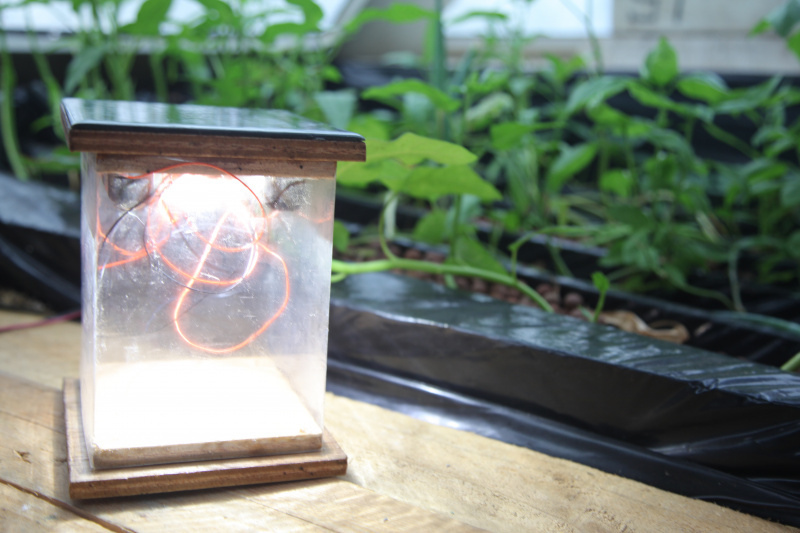
This tutorial allows you to make a solar lamp equipped with a USB charger. It uses lithium cells that are reused from a old or damaged laptop. This system, with a day of sunlight, can fully charge a smartphone and have 4 hours of light.
Sommaire
Sommaire
[masquer]- 1 Description
- 2 Sommaire
- 3 Introduction
- 4 Video d'introduction
- 5 Étape 1 - How it works
- 6 Étape 2 - Manufacturing stages
- 7 Étape 3 - Removing the cells from the computer battery
- 8 Étape 4 - Measure voltage of cells and ther capacity
- 9 Étape 5 - Realisation of the 3 different modules
- 10 Étape 6 - Connection of the 3 modules
- 11 Étape 7 - Building the case - Version 1
- 12 Étape 8 - Building the case - Version 2
- 13 Étape 9 -
- 14 Notes et références
- 15 Commentaires
Introduction
Lithium is a natural resource whose stocks are increasingly used for electric cars, telephones, and computers. This resource is gradually being depleted over time. Its increased use in battery manufacturing is mainly due to its ability to store more energy than nickel and cadmium. The replacement of electrical and electronic equipment is accelerating and it is becoming an increasingly important source of waste. France currently produces 14kg to 24kg of electronic waste per inhabitant per year. This rate increases by about 4% per year. In 2009, only 32% of young French people aged between 18 and 34 years old, have once recycled their electronic waste. In the same year 2009, according to Eco-systèmes, from January to September 2009, 113,000 tonnes of CO2 were avoided through the recycling of 193,000 tonnes of DEEE.
However, this waste has a high recycling potential. In particular, the lithium in the cells of computer batteries can be recovered and reused. When a computer battery does not work anymore, it is because one or more cells are defective, but some remain in good condition and can be reused. From these cells it is possible to create a separate battery, which can be used to power an electric drill, recharge your phone or be connected to a solar panel to operate a lamp. By associating several cells it is also possible to form batteries of storage of more important device.
The design of this lamp is inspired by a system documented by the Nomade des Mers expedition on the island of Luzong in the northern Philippines. The association Liter of Light has been installing similar systems in villages without electricity for nearly 6 years, also organizing training to allow villagers to repair the lamps independently (already 500 000 lamps installed).
(Turn on subtitles for the video, you will have every details !)Youtube
Matériaux
- Used laptop battery (Li-ion 18650)
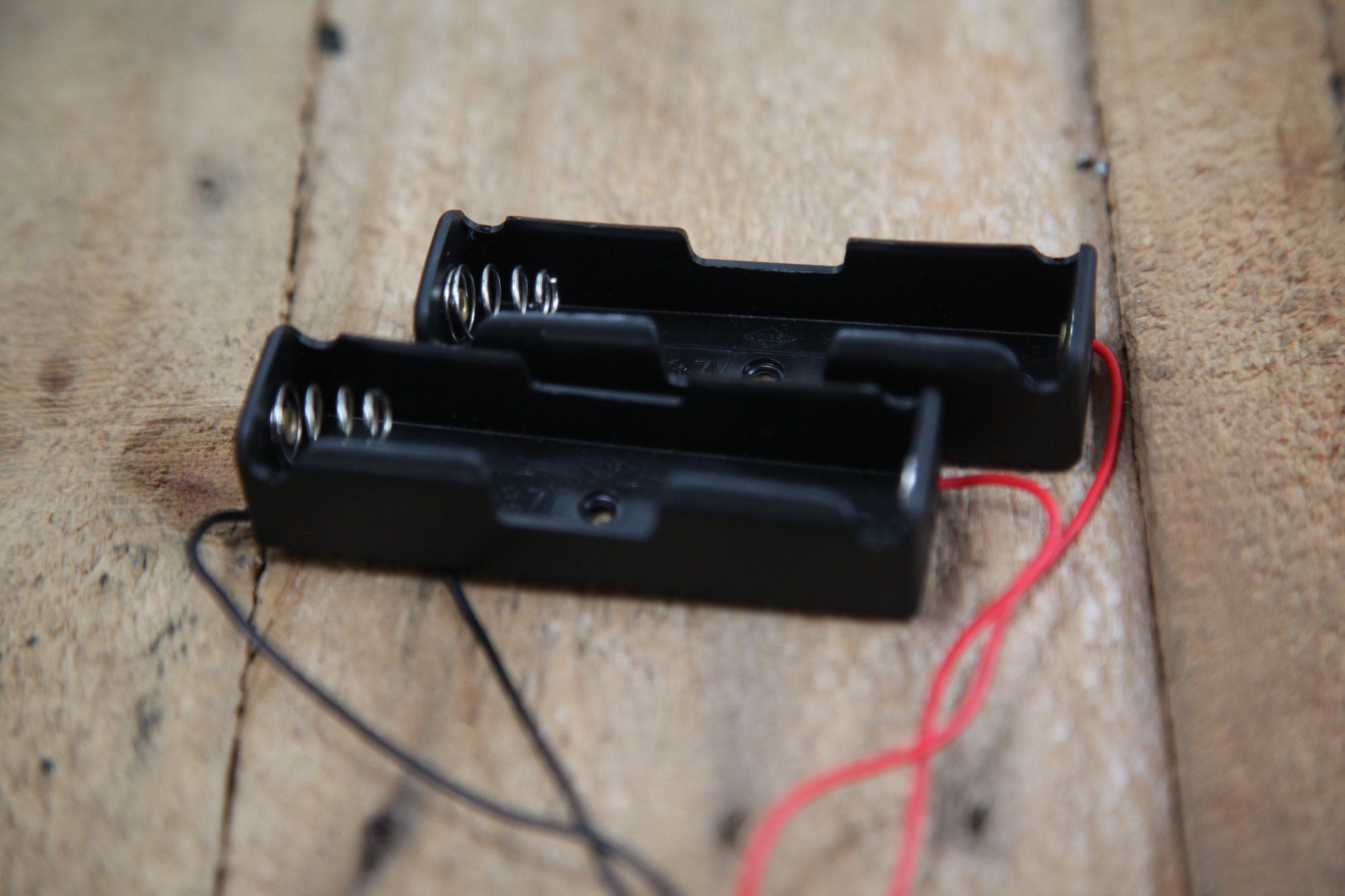
- Li-ion 18600 battery holders
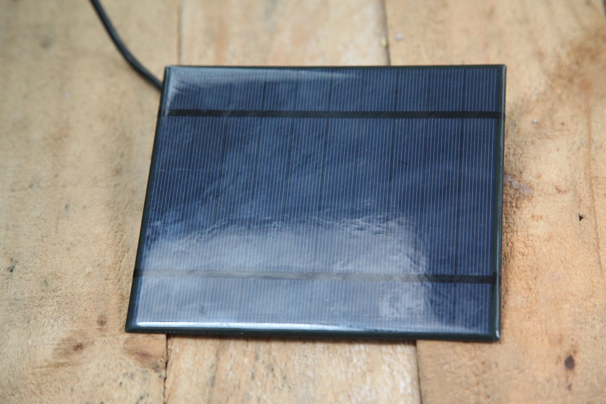
- Solar panel 5V-6V / 1-3W
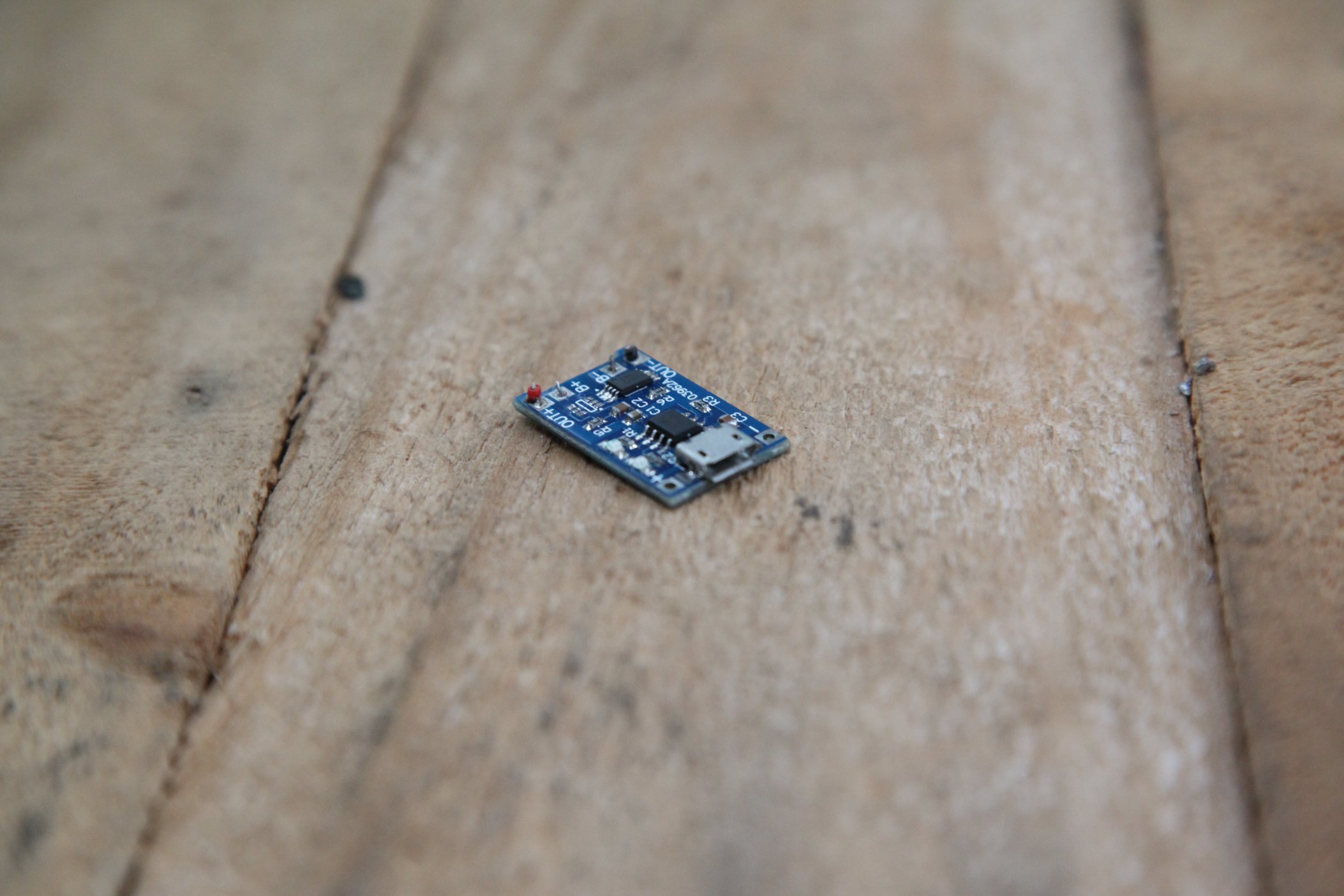
- Charge and discharge regulator (ex: 4-8V 1A Mini Li-ion USB Arduino Battery Charger TP4056)
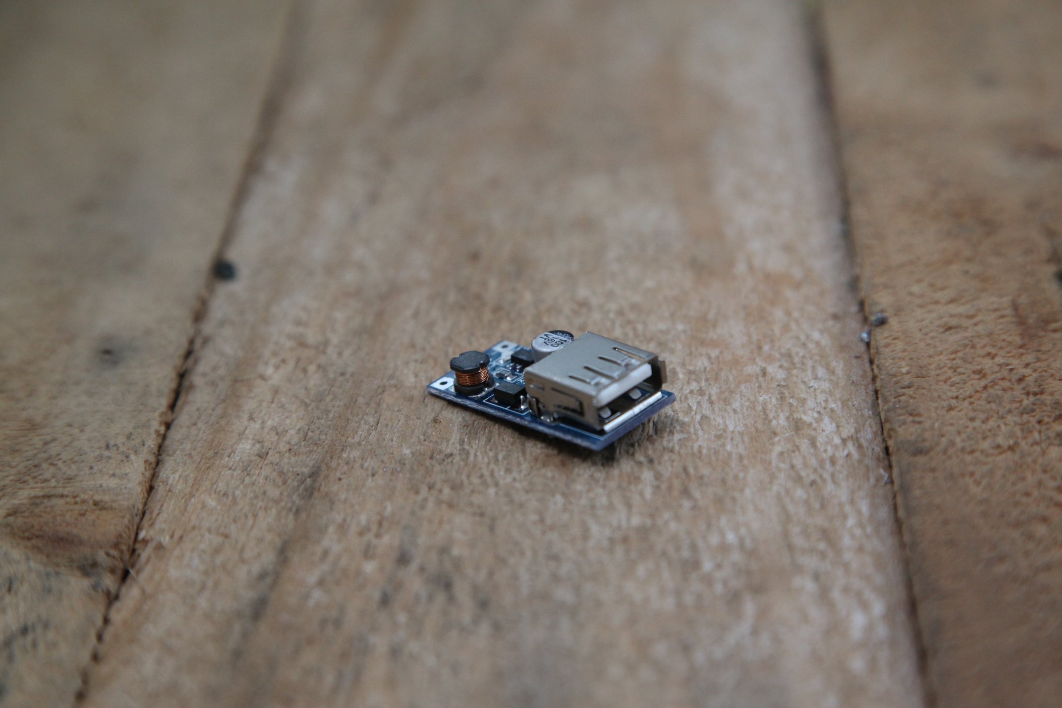
- DC/DC tension converter DC/DC booster MT3608 (electrical component that will transform the 3.7 V of the batteries into 5 V)
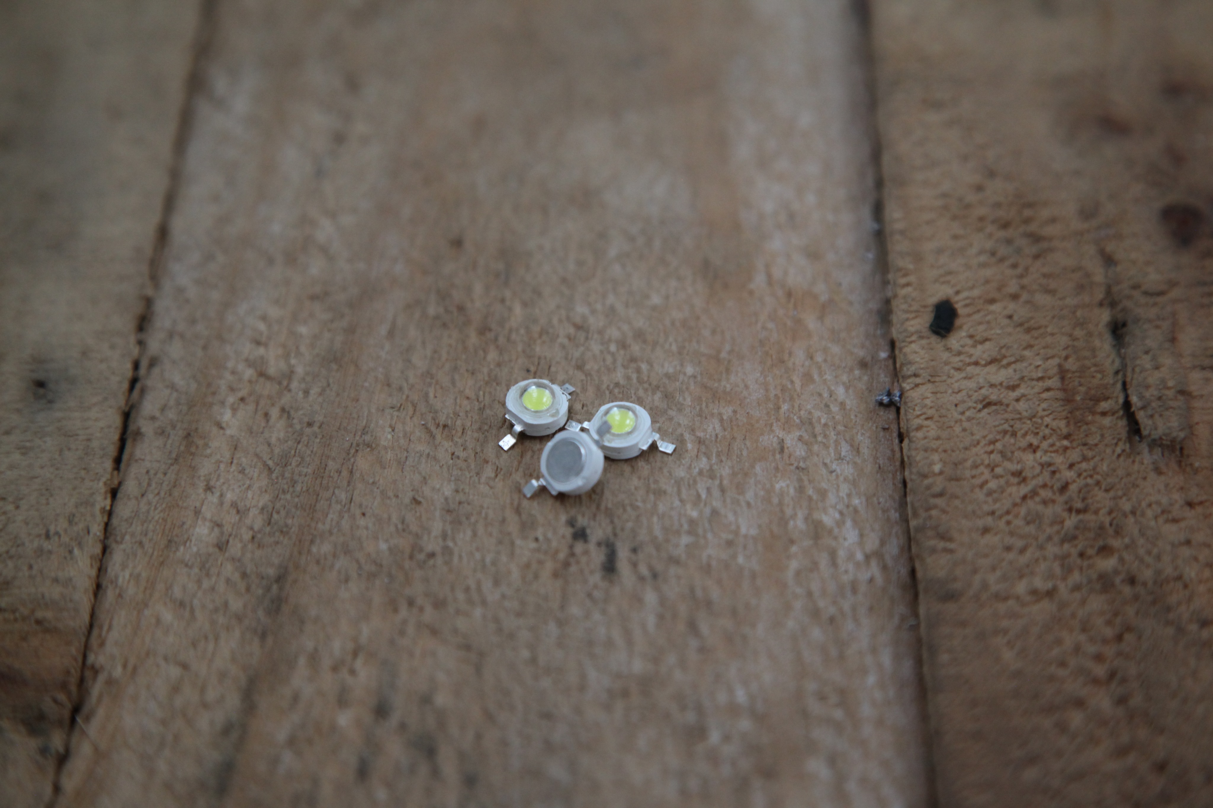
- High power LED Lamp (ex : LED boutons 3W max)
- Switch (to open the circuit and cut off the light)
- Electric tape
- Box
Outils
Cells extraction
- Gloves (to avoid cutting with the plastic of the computer battery or with the nickel ribbons that connect the cells)
- Hammer
- Chisel
- Cutting pliers
For the lamp fabrication :
- Glue gun (and glue sticks)
- Heating gun or small torch
- Wood saw
- Screw driver
Étape 1 - How it works
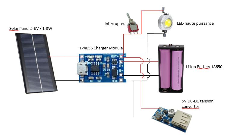
This tutorial shows how to recover computer cells to make a new battery. Powered by a solar panel, or by a USB port, it will allow you to light an LED lamp.
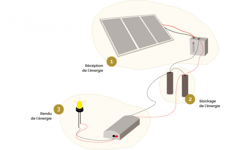
The system works around three modules:
- the energy reception module: the solar panel and its charge controller
- the energy storage module: the battery
- the module that gives back the energy: the LED lamp and its voltage regulator
Energy Receiving Module: Photovoltaic Panel & Charge Controller
The photovoltaic panel concentrates the energy of the sun. It allows to recover its energy in order to store it in the battery. But be careful, the amount of energy received by the panel is irregular depending on the time of day, the weather... it is important to install a charge/discharge regulator between the panel and the battery. This will be protected against overload, among other things.
Energy storage module: the battery
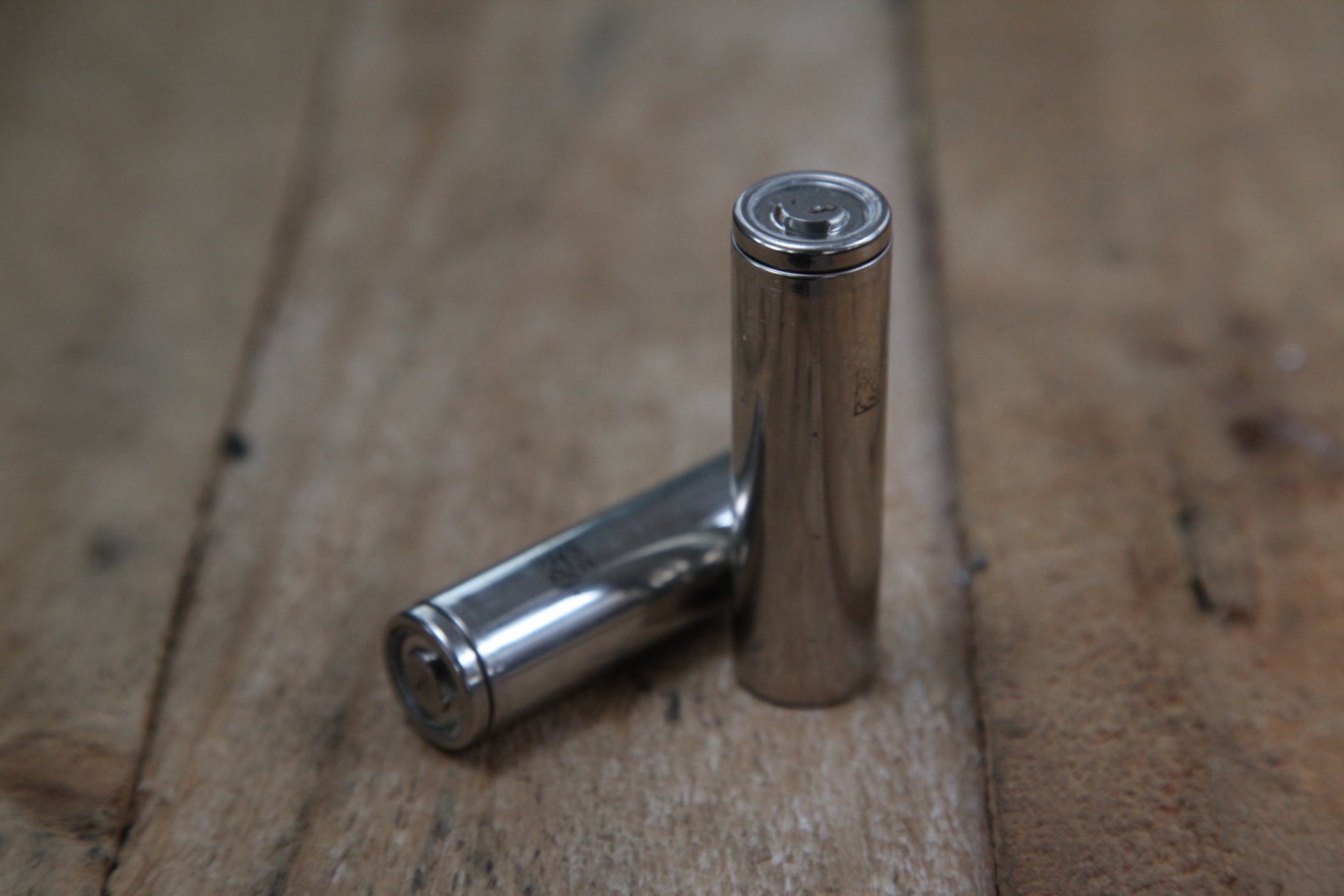
It is composed of two lithium cells recovered from a computer. To put it in a nutshell, a battery is a bit like a box containing several batteries: each of them is a cell, a unit that supplies power to the device by electrochemical reaction.
The cells found in computers are lithium cells. They all have the same capacity to store energy, but their ability to make it is different for each. To form a battery from cells it is important that they all have the same ability to deliver energy. It is therefore necessary to measure the capacity of each cell to compose homogeneous batteries.
Module that renders the energy: the LED lamp, the 5V USB port and its voltage converter
Our battery supplies us with 3.7V power and the LED lamps we used operate at the same voltage. In addition, the USB ports provide a voltage of 5V. We therefore need to transform the cell energy from 3.7V to 5V: using a voltage converter called DC/DC booster
Étape 2 - Manufacturing stages
1) Removing the cells from the computer battery
2) Measure voltage of cells
3) Realisation of the 3 modules
- solar panel + charge regulator
- battery
- LED light + charge regulator
4) Link of the 3 modules :
- solar panel + charge regulator
- the battery
- LED light + charge regulator
5) Build a box
6) Integration of modules in the box
Étape 3 - Removing the cells from the computer battery
For this part we suggest you to look at the following tutorial : Récupération de batteries
- Put on gloves to protect your hands
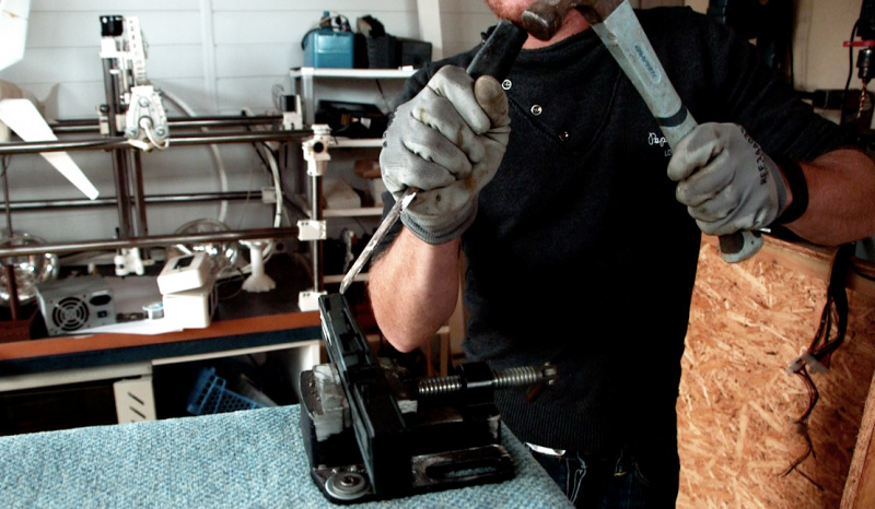
- Put in place the battery, and open it with a hammer and a chisel
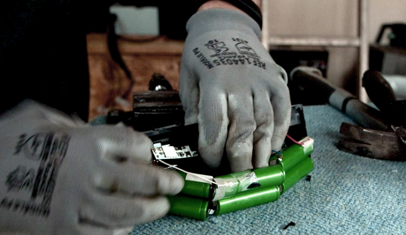
- Isolate each cells by removing every other parts. (image 2)
Étape 4 - Measure voltage of cells and ther capacity
For this part we suggest you to look at the following tutorial : Récupération de batteries
Voltage measure:
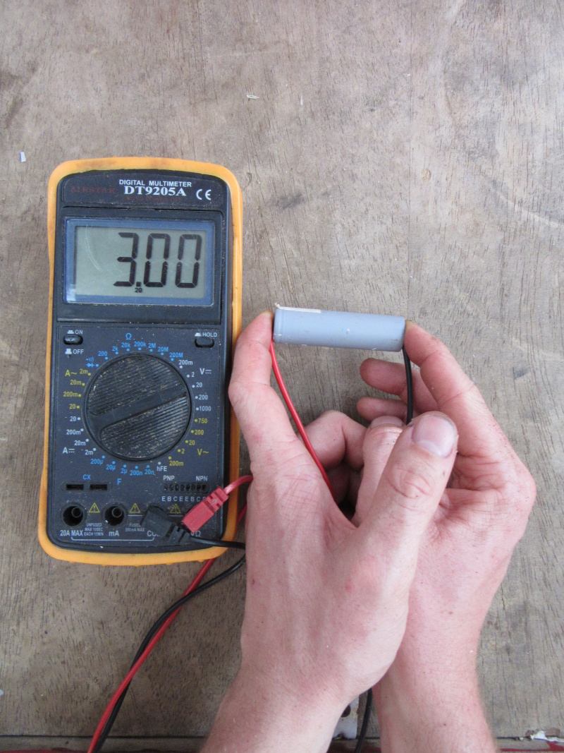
We start by measuring the voltage of each cells in order to check if they are working properly. Every cells that have a voltage lower than 3V will not be able to be used in this project and should be recycle.
- Using a multimeter, in DC mode, measure each cells and check the one that are usable ofr the project.
Be carreful : If the computer battery seems to have liquid on the outside, do not open the box, lithium is harmful in high dose.
Measure the capacity :
To measure the capacity of a cell, we have to charge it to the maximum and then discharge it. Those cells are lithium based, and need a specific charge and discharge system, ususally the maximal charge is 4,2 V and the minimum is 3V. Going over those limits will damage the cell.
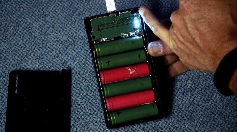
- Use a PowerBank : it will alow you to charge many cells at once with a USB port.
- Charge the cells and wait until the charge is complete (all the light should be on), it will be done in about 24 hours. (image 3)
- The cells will be charge at their maximum (4,2V), now we have to discharge them.
- You should use an Imax B6 : a tool that allow to discharge the cells and check their capacity.
- How to use the tool :
- the voltage : it will ask you which type of cells you would like to check, you should choose the lithium one. It will automatically regulate the discharge at 3V minimum.
- the intensity : set to 1A in order to have a quick and secure discharge. In this condition, the discharge should take between 1 hour and 1 hour and half.
- Connect the magnet to the crocodile clips, then connect to the cell, the magnet help to let the current pass through the Imax B6 to the cells. (image 4)
- Discharge the cells until they are completely empty.
- Note the capacity on the cell. The higher the better.
- Sort your cells by capacity : <1000 mA, between 1000-1300, 1300-1500 and >1800 mA.
Remark : It is important to do homogeneous batteries, with cells that have a similar capacity
Étape 5 - Realisation of the 3 different modules
Module 1 : Solar panel and charge regulator
- Use a black and a red wire, use a pliers to stripe the wires.
- Soldier the red wire on the positif side of the panel and the black on on the negative side.
- The charge regulator has 2 inputs : IN- and IN+ (which are indicated on the component).
- Weld the red wire (positive) with the IN+ input of the charge regulator and the black wire (negative) with the IN- input (image 5).
Module 2 : Battery
- Insert the lithium cell in the battery holder.
Module 3 : LED / USB converter
The voltage converter DC/DC has two inputs and two outputs :
Inputs : VIN + and VIN - / Outputs : OUT + and OUT -
- Take two wires (red and black).
- Weld the red wire with the VIN+ input of the voltage converter and the black wire with the VIN- input.
The LED has two input wires : one positive and one negative.
Caution: Wire polarity is not indicated on the LED. In order to identify it, use an ohmmeter. The wire is positive when it displays a null value. When it displays a higher value, the wire is negative.
Wath that the tension in use of the LED is around 4V, if not, add a resistance connected in serie to lower the tension (typically, 2 Ohm allow te lower the tension from 1 V).
- Weld the LED positive wire to the OUT+ output of the voltage converter and the LED negative wire to the OUT- output. (image 7)
Étape 6 - Connection of the 3 modules
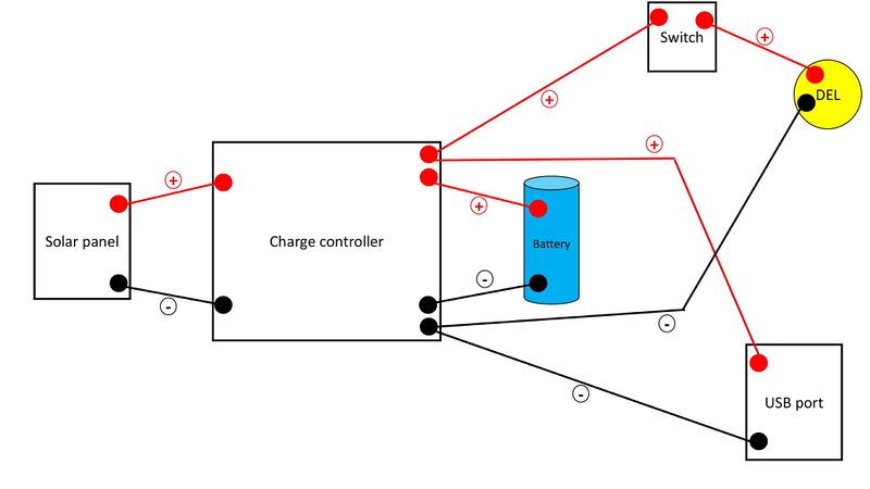
The charge regulator has 2 inputs : IN- and IN+ (which are indicated on the component).
- Weld the red wire of the solar pannel (positive) to the IN+ input of the charge regulator and the black wire (negative) to the IN- input.
- The charge regulator has 2 inputs : B- and B+ (which are indicated on the component).
- Weld the red wire of the battery holder (positive) to the B+ input of the charge regulator and the black wire (negative) to the B- input.
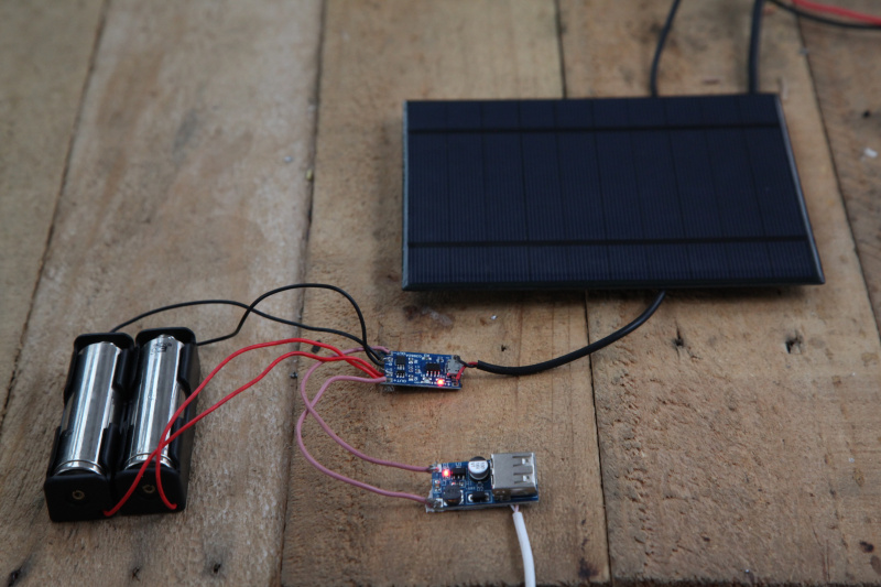
- Weld the red wire (positive) of the USB/LED converter module to the OUT+ output of the charge regulator. Weld the black wire (negative) to the OUT- output. Remark : The electric circuit is now closed and the light turns on.
- Cut the positive wire connecting the regulator to the converter in order to open the circuit and weld the switch in series. It will be used to open and close the circuit.
The commutation type of the switch is On-Off-On : the red wire coming from the lamp is welded on the middle electrical connection (Off), and the red wire coming from the charge regulator is welded on one of the other electrical connection (On).
Étape 7 - Building the case - Version 1
Version 1 : Tupperware
This design originates from Open Green Energy, do not hesitate to consult the original tutorial. We are sharing it because it seems really interesting. However, the case shall be adapted to our circuit, in particular for the USB output. We will propose soon our own model inspired from this design.
Étape 8 - Building the case - Version 2
Version 2 : Large size thermoformed bottle- A 5L can of water
- Plywood boards (or raw wood) between 1 and 2cm thick
- A cleat of 80 cm minimum (width between 3 and 5cm)
Building of the two bases :
These are the two ends of the lamp, the upper one hosting the solar panel on one side and the electrical circuit on the other, the lower one just serving to close the lamp while sealing it.
- Cut 2 boards of 15/13cm and 2 boards of 11/13cm. Place on each large board a small one, taking care to center them well. Each pair will be screwed later.
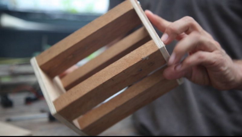
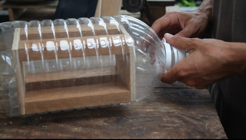
- Cut 4 sections of about twenty centimeters in the cleat. Position them at the 4 corners of the small planks cut above (the 11/13 cm) and screw them in place. On the other side position the other board and screw it in the same way. We thus obtain a parallelepiped of dimensions 11/13/20 which will be used to thermoform the plastic bottle (see photo).
Thermoforming of the lamp envelopp
- Cut the bottom of the 5L bottle and insert the mold vertically (the 20cm side in the length of the bottle)
- Gently heat each side of the rectangle with a heat gun (or hair dryer) (the heat gun should be about 10 cm from the bottle). Once the bottle has taken the shape of the model, continue to heat to erase the patterns and tighten the plastic.
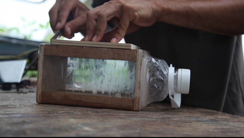
- Leaving the deformed bottle on the mold, cut the top of the bottle flush with the mold and make a clean cut about 17 cm from the first.
- Once the cuts have been made, unscrew the cleats on both sides in order to be able to unmold the form (the removal of the plastic will have caused a significant tightening of the mold).
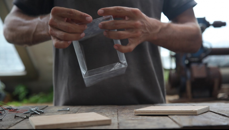
- A chaque extrémité de la bouteille déformée, replier à 90° vers l’intérieur des languettes d’une largeur d’environ 1 cm biseautées de chaque côté (voir photo). Celles-ci viendront s’immiscer entre les deux planchettes de chaque socle afin d’améliorer l’étanchéité de la lampe. Pour pouvoir plier correctement les languettes, tracer une fine ligne au cutter à l’intérieur puis plier à la main.
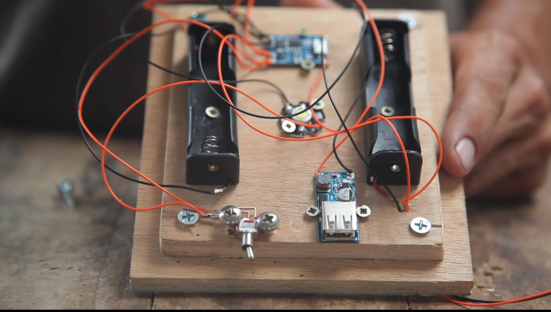
Once the body of the lamp is completed, all that is left is to integrate the electrical circuit.
Integration of the electric circuit :
- Pour cela, reprendre une des petites planchettes utilisées pour le moule (11/13cm) et y visser tous les composants comme désiré, sachant qu’un minimum de symétrie permet de garantir l’équilibre de l’objet (voici en photo un exemple de disposition). Attention à bien fixer le port USB et l'interrupteur, afin qu'ils ne bougent pas lorsqu'ils seront manipulés
- A l’aide d’un marqueur tracer sur l’enveloppe en plastique l’emplacement du bouton ON/OFF et de la prise USB
- et faire les trous correspondant.
- Placer la planche avec le circuit à l’intérieur de l’enveloppe en plastique puis visser une des planches de 15/13cm dessous en prenant soin de bien coincer les languettes entre les deux planches
Fixation du panneau solaire :
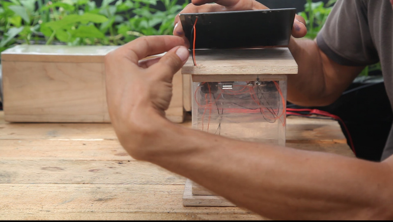
- Placer le panneau sur la grande planchette, déterminer l’emplacement des sorties + et – du panneau et faire un trou d’environ 5mm à cet endroit dans les deux planchettes (vérifier qu’aucun composant n’est à cet endroit auquel cas il faudra décaler le trou suffisamment).
- Faire passer les fils venant du contrôleur de charge dans ce trou et les souder aux sorties correspondantes.
- Pour coller l’idéal est d’utiliser un tissu fin collé à la planchette puis d’y coller le panneau (à la super glu par exemple).
- Pour le socle de la lampe faire de même de l’autre côté ; placer la petite planchette à l’intérieur de l’enveloppe puis y visser la grande en prenant soin de coincer les languettes entre les deux.
- Pour l’étanchéité de la prise USB, agrafer un petit rectangle de chambre à air de vélo sur l'extérieur, pour couvrir l'ouverture du port.
Étape 9 -
Comme tout le travail du Low-tech Lab, ce tutoriel est participatif, n'hésitez pas à ajouter les modifications qui vous semblent importantes, et à partager vos réalisations en commentaires.
Notes et références
Do not hesitate to ask any question or suggestion about this tutorial, we will open a new section to address it. If you have made the lamp, share it ! #solarlamp #lowtechlab
Published


 Français
 English
 Deutsch
 Español
 Italiano
 Português
Hello, thanks for the tutorial, I find that sometimes my batteries are less charged after putting the solar panel in the sun. Could that be because whenever there is not enough light, the current is inverted and goes out of the battery? Would it then be better to have a diode to prevent the current to change direction when the luminosity drops? Or would it be that my panel (5V) is not powerful enough? What's your experience with the setting described above (I think I have the same components)?