Description
Build a wind turbine from printer stepper engine
Sommaire
Sommaire
[masquer]- 1 Description
- 2 Sommaire
- 3 Introduction
- 4 Video d'introduction
- 5 Étape 1 - How it works
- 6 Étape 2 - Manufacturing steps
- 7 Étape 3 - The wind turbine - Motor preparation
- 8 Étape 4 - The wind turbine - Motor axis
- 9 Étape 5 - The wind turbine - Blades prep
- 10 Étape 6 - L'éolienne - Aileron et base des pales
- 11 Étape 7 - L'éolienne - Assemblage
- 12 Étape 8 - Le circuit électrique - Redresseurs
- 13 Étape 9 - Le circuit électrique – Condensateur
- 14 Étape 10 - Le circuit électrique – Régulateur de tension ou rehausseur de tension
- 15 Étape 11 - Le circuit électrique – Raccordement du port USB
- 16 Étape 12 - Protection du moteur
- 17 Étape 13 - Utilisation
- 18 Notes et références
- 19 Commentaires
Introduction
"In Africa, 600 million people in rural areas don't have access to electricity."
CONTEXT :
Access to energy, and especially access to electricity, is a prerequisite for the economic and health development of a country. While global energy consumption has almost doubled since the 1970s, the share of poor countries has steadily increased. Today, it is estimated that 2 billion people do not have sufficient access to energy to live in acceptable conditions, and 1.6 billion people do not have access to electricity at all. This has dramatic health and environmental consequences. Renewable energies such as wind could be a solution: A wind turbine converts the kinetic energy of the wind into electrical energy.
THE INDUSTRIAL WIND TURBINE :
A 2-megawatt industrial wind turbine produces approximately 4400 megawatts / hour annually, which represents the power consumption of about 2,000 people. Industrial wind turbines are filled with sensors, moving parts, regulators and mechanical parts of all kinds. They are complex in manufacturing and their environmental impact on construction is far from neutral. Moreover it is not possible today to repair these wind turbines with local means.
THE LOW-TECH WIND TURBINE :
Easily build a low-tech wind turbine from recycled materials for less than 10 € is possible! Lower in power than industrial wind turbines, it can be used for local applications: charging a phone, lighting LEDs, operating a small pump ... For such applications, a few watts are enough.
This wind turbine can therefore be very useful for remote areas with no access to grid electricity and that benefit from favorable winds. In Senegal, for example, only 40% of the population is connected to the electricity grid in urban areas and only 10% in rural areas. The possibility for people to be able to generate electricity from a self-built wind turbine would be a great opportunity.
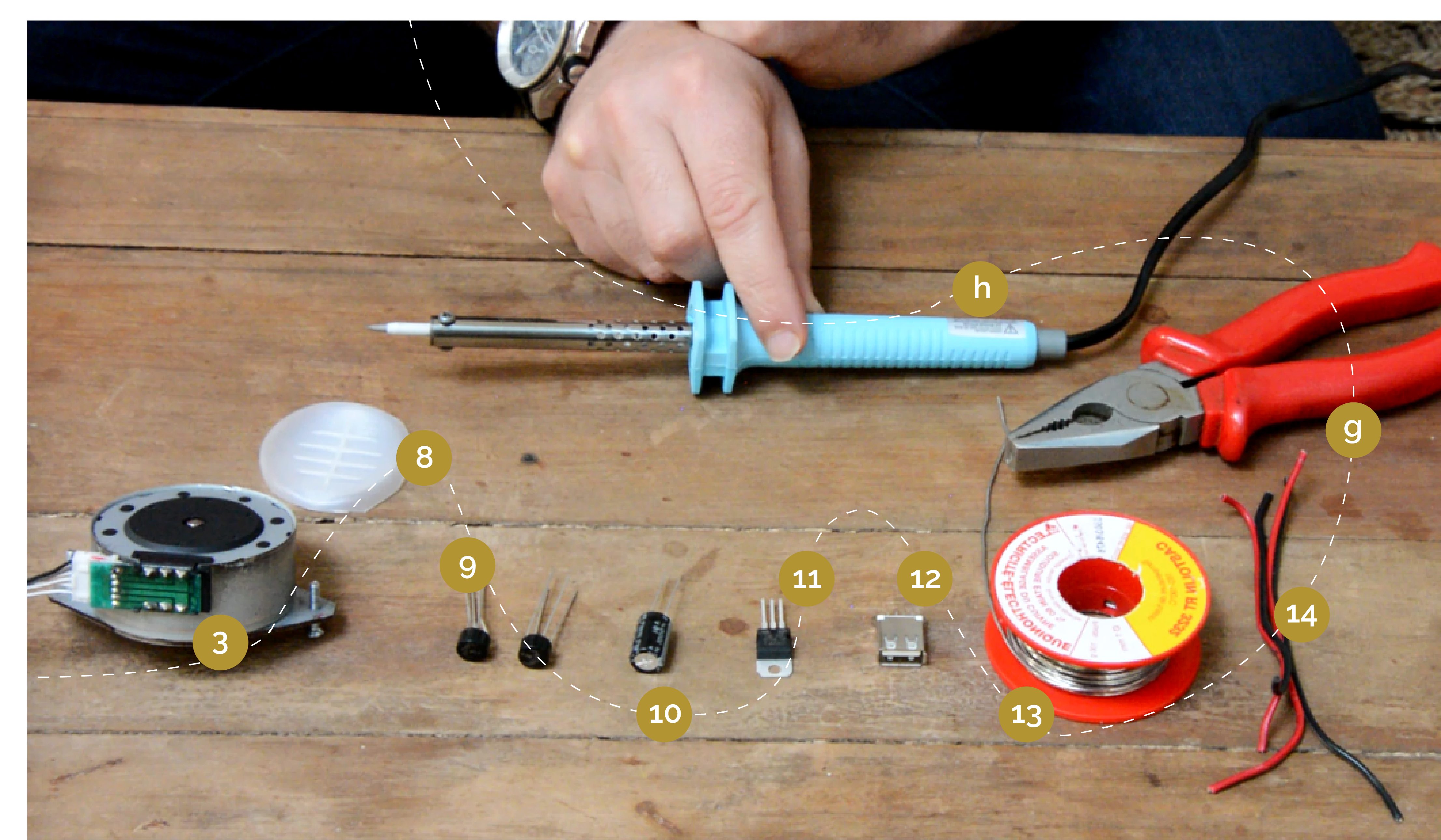
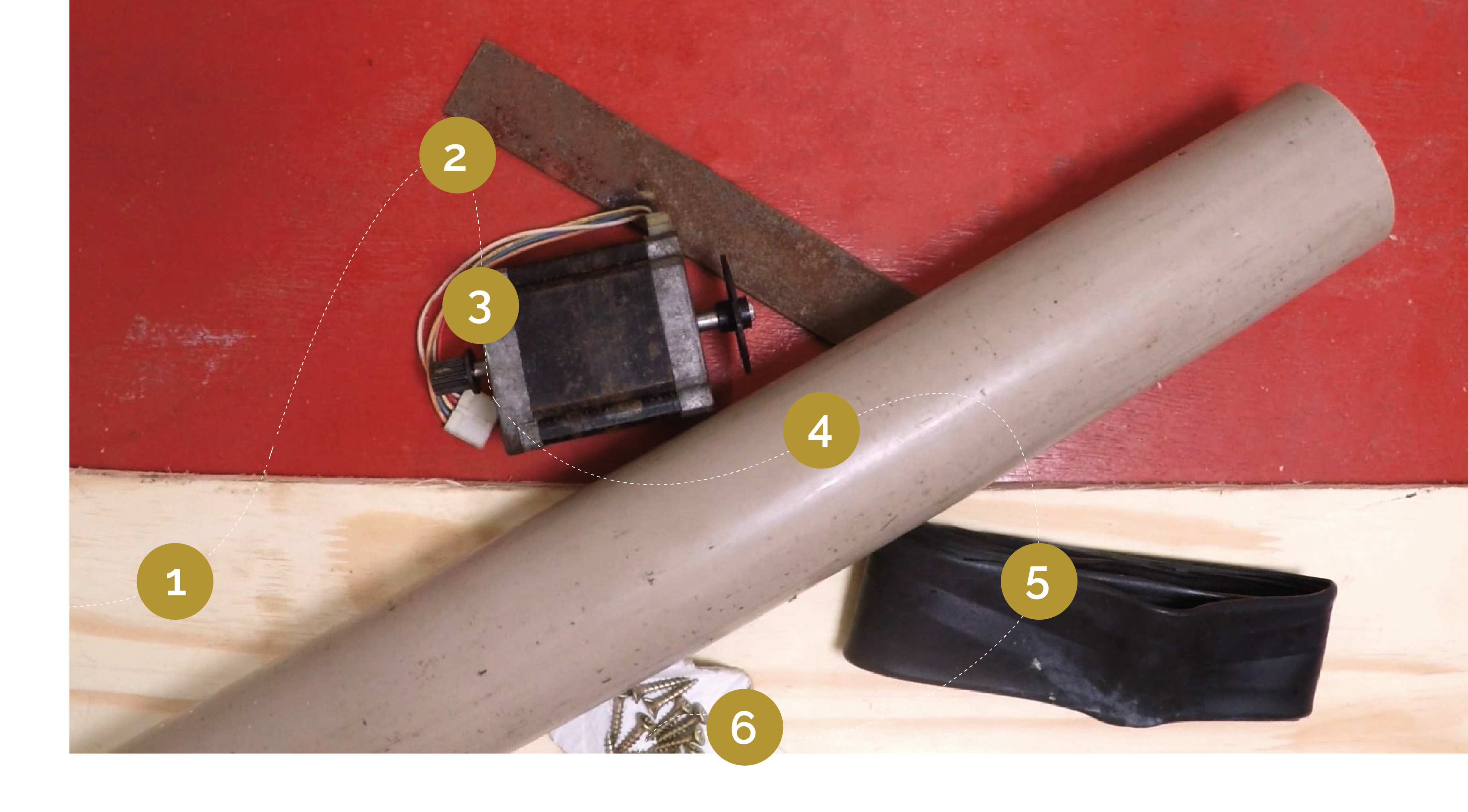
Matériaux
Wind turbine :
1 - A wooden board (at least 10 mm thick)
2 - A flat iron plate (at least 2 mm thick)
3 - A printer stepper motor (with its connection pin)
4 - A PVC tube (55 mm < diameter < 100 mm and at least 3 mm thick)
5 - A bicycle inner tube
6 - Wood screws
Electric circuit: </ u>
3 - The printer stepper motor
8 - A plastic support to accommodate the various elements of the system (recoverable on a flat part of the printer case)
9 - Two voltage rectifiers or diode bridge W
10 - A 1000μF 16V capacitor W
11 - A voltage regulator W LM7805 to set the voltage to 5V, we can also use the LM7812 to set the voltage to 12V
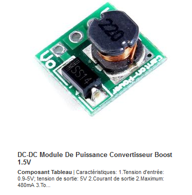
11' - Instead of the voltage regulator you can use a voltage booster or DC / DC Booster or Step Up which will provide an output voltage of 5V (USB) with an input voltage ranging from 0.9 to 5V .
12 - A USB connector
13 - Tin for soldering
14 - Electric wire
Find the 3D model of this wind turbine by following this link
Outils
Wind turbine: </ u>
a - A vice
b - Wood and metal saw
c - Ruler
d - Screwdriver
e - Voltmeter
f - Alligator clips
Electric circuit: </ u>
g - Cutting pliers
h - Soldering iron
Étape 1 - How it works
This tutorial shows how to make a small wind turbine from old stepper engine from printers or copiers. It will allow for example to recharge a mobile phone.
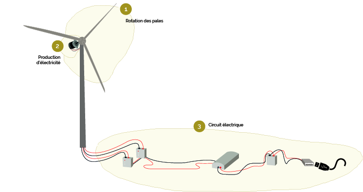
1 - The rotation of the blades
Under the effect of the wind, the propeller, also called rotor, starts up. His blades turn.
The 4 blade rotor is placed at the top of a mast to take more wind.
2 - Electricity generation
The propeller drives a printer stepper motor.
Thanks to the energy provided by the rotation of the blades, the stepper motor produces an alternating electric current.
3 - The electric circuit
The circuit "treats" the output current of the motor, so that it can be used to charge a phone, or other device from a USB port.
It is made of :
- Rectifiers that "straighten" the voltage at the output of the motor to have a continuous current.
- A capacitor to redistribute electricity constantly, because the wind provides a non-continuous energy.
- A voltage regulator that limits the voltage of the electric current produced by the motor to the desired voltage, here 5V.
The wind turbine requires a minimum wind speed of about 10 to 15 km / h to start its rotation.
Étape 2 - Manufacturing steps
The wind turbine
1 - Motor preparation
2 - Motor axis
3 - Blades preparation
4 - Fin and blades basis
5 - Assembly
The electric circuit
1 - Rectifiers
2 - Capacitors
3 - Voltage regulator
4 - USB port connection
Motor protection
Étape 3 - The wind turbine - Motor preparation
1 - Cut the 6 wires coming out of the stepping motor, strip them and twist them.
From here, two possible methods :
Method #1
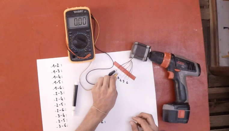
In order to know which of the 6 wires has the highest output voltage, you should test all possible motor output pairs, and select the two highest ones.
2 - Using a screwdriver, an "alternating" voltmeter and crocodile clips, test the pairs of wires. Record the voltage for each of the pairs. (image 1)
3 - Select the two wire pairs with the highest output voltage (here 10V, this may vary depending on the motor). They are the ones who will then be connected to the electric circuit of the wind turbine.
* Tip: Mark with a colored tape the two useful pairs to no longer mix them with others.
Method #2
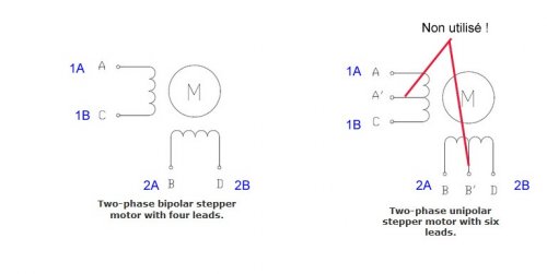
In fact the stepper motors are schematically constituted of two or four coils:
(image 2)
As shown in the picture, in the case of a 6-wire motor we will not use the midpoint. In fact, we are going to combine two coils to make one and generate more tension.
From here it's very simple :
1) Place your multimeter in ohmmeter mode, or even better in contact detection mode (you know, it makes this "BBIIIIPPPPP !!" noise when the two probes are touching).
2) First of all separate the two sets of wire for each of the coils.
For a 4-wire motor it's very simple: you take a wire on a probe, and with the other probe you touch the other wires. The one for which the meter does "BBBIIIIIPPPPP !!!" or for which the measured resistance becomes low (it depends on the motor but a wide range would be 1 to 50 ohms) you are good, you have found your coil and by elimination the two remaining wires are for the other coil.
For a 6-wire it's hardly more complex: we apply the same method to determine sets of 3 wires per coil. Then we go into ohmmeter mode and look which pair of wires per coil gives the greatest resistance ==> bingo you found the right wires for one coil, repeat the operation for the other and you are good !
Note: there are also 8-wire motors. In fact it's a 6-wire (so 4 coils) but with 4 independent coils (so pretty much like a 4-wire...). Use the same method as the 4-wire, but more times.
Étape 4 - The wind turbine - Motor axis
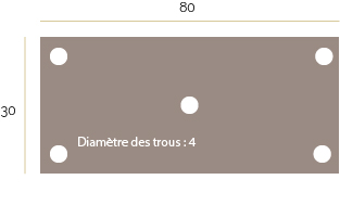
1 - Cut out a metal plate of 80x30 cm. Drill 5 holes of diameter 4.
* Tip: You can get help from diagram 1 above to cut and drill the plate.
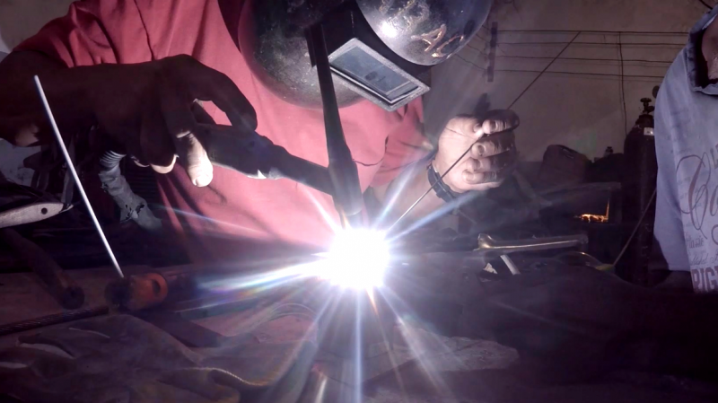
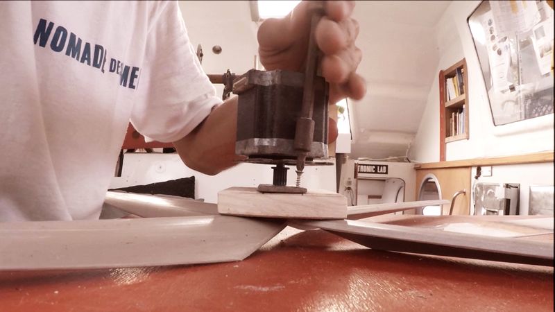
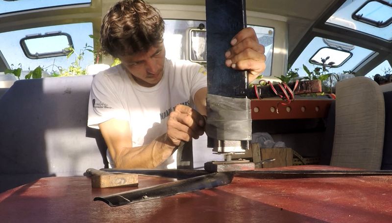
2 - Weld the metal plate to the motor axis at the plate's center hole. (image 2)
Étape 5 - The wind turbine - Blades prep
From the formula connecting the wind speed, a given surface and the power of the wind on this surface:
We can establish this formula, allowing us to calculate the length of the blades:
Where :
- L = length of the blade in m
- P = characteristic power of the motor in W
- V = wind speed in m / s (depending on the location)
Usually, the blade length must be 35 cm.
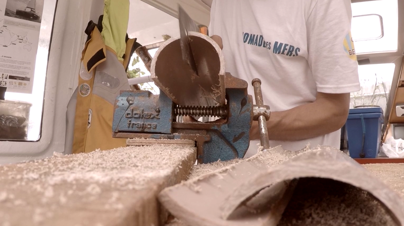
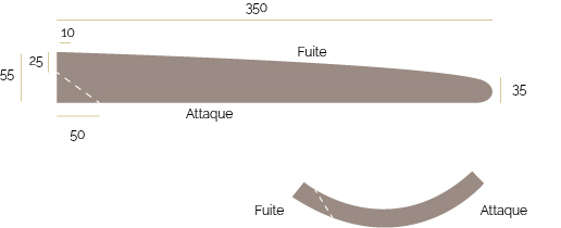
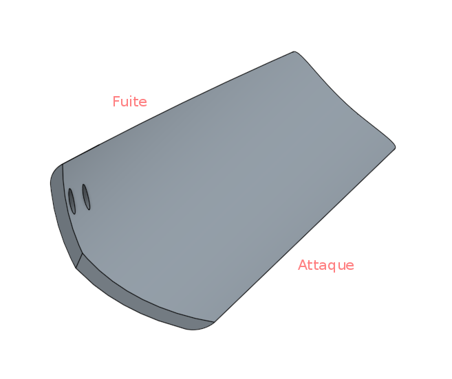
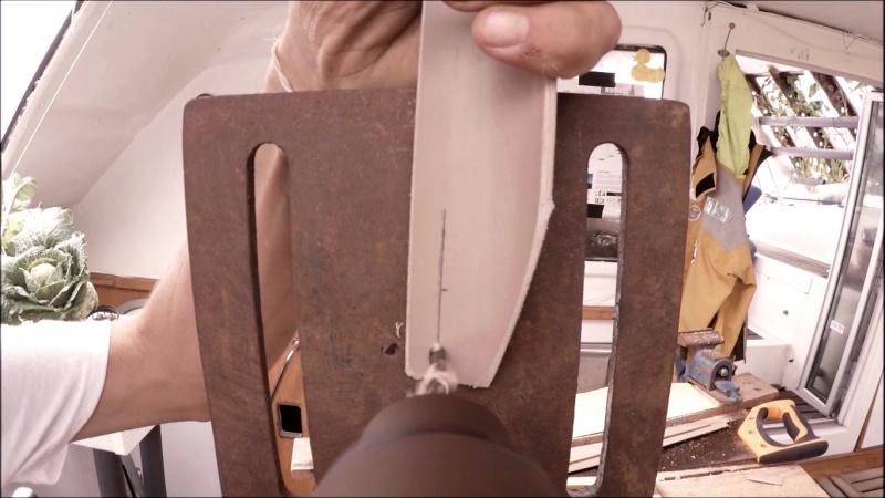
1 - Draw and cut the blades in a PVC tube. (image 3)
* Tip: You can get help from diagram 2 above to draw the shape of the blades.
Figure 3 shows the direction of the cut.
2 - Sand the edges of each blade: the leading edge must be rounded, and the trailing edge sharpened.
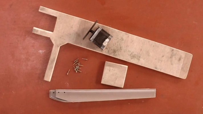
3 - Drill the blades: the drilling is done closer to the trailing edge so that it can be fixed flat on the plate that carries the blades. (Image 4)
Your blades are ready !
Étape 6 - L'éolienne - Aileron et base des pales
1 - Dans une planche de bois, dessiner et découper l’aileron. (image 5)
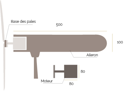
* Astuce : Vous pouvez vous aider du schéma 3 ci-dessus pour dessiner la forme de l’aileron.
2 - Dans cette même planche découper un carré de la taille de votre moteur (ici 80x80cm) qui servira à accueillir les pales précédemment découpées afin de les solidariser entre elles. (schéma 3 - base des pales)
3 - Sur l’aileron, marquer l’emplacement du moteur de façon à ce qu’il puisse s’encastrer de force dans la forme. (schéma 3 - moteur)
* Remarque : Les dimensions de cette partie dépendent de la taille de votre moteur.
4 - Poncer les rebords de l’aileron pour un meilleur aérodynamisme et un meilleur rendu. (image 5)
Étape 7 - L'éolienne - Assemblage
1 - Visser les pales (découpées à l’étape 3) sur leur base (découpée à l’étape 4).
2 - Visser la base des pales sur la plaque en métal. Utiliser les trous percés dans la plaque métallique à l’étape 2. (image 6)
3 - Vérifier qu’il y ait le même angle entre chacune des pales.
Étape 8 - Le circuit électrique - Redresseurs
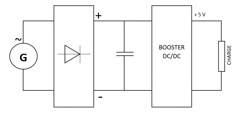
Le circuit électrique est celui du schéma 4.
En sortie du moteur, on obtient du courant alternatif. Or, pour charger une batterie ou allumer une lampe, il est nécessaire d’avoir du courant continu. Pour transformer du courant alternatif en courant continu on utilise deux redresseurs : ils « redressent » la tension à la sortie du moteur.
Chaque redresseur dispose de 4 pattes : Les deux pattes centrales sont les pôles alternatifs du condensateur Les deux pattes extérieurs sont les pôles positifs et négatifs du condensateur
* Astuce : sur la tête du redresseur chacun de ces 4 pôles sont indiqués.
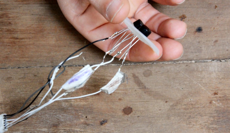
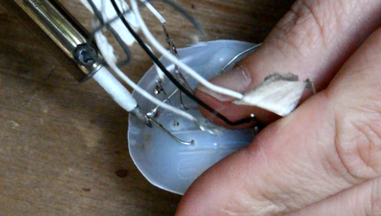
1 - Souder les sorties tension du moteur pas à pas (précédemment sélectionnées) aux entrées alternatives de chaque redresseur : le premier couple avec les pôles alternatifs du premier redresseur, et le deuxième couple avec les pôles alternatifs du deuxième redresseur. (image 7)
* Astuce : Il est possible d’utiliser de la gaine thermorétractable pour couvrir les connections afin de protéger le système.
2 – Souder les sorties négatives des deux redresseurs entre elles, puis souder les sorties positives des deux redresseurs entre elles. (image 8)
Étape 9 - Le circuit électrique – Condensateur
L’énergie fournie par l’éolienne n’est pas constante car la vitesse du vent varie en permanence. Il faut donc stocker provisoirement la surcharge afin de pouvoir la redistribuer de façon constante. On utilise pour cela un condensateur.
Le condensateur est un composant polarisé : - la borne positive est la tige la plus longue - la borne négative est la tige la plus courte
* Astuce : Il est également possible de se référer au symbole “-” inscrit sur la borne moins.
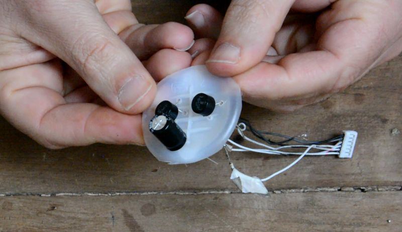
1 - Souder les pôles négatifs entre eux puis les pôles positifs entre eux en sortie de redresseur. (image 9)
* Astuce : si les tiges de vos différents composants sont trop courtes pour se souder entre elles, vous pouvez les relier à l’aide de fils électriques.
Étape 10 - Le circuit électrique – Régulateur de tension ou rehausseur de tension
Le régulateur de tension permet de récupérer un courant 5V en sortie.
*Remarque : Chaque régulateur est différent, si vous voulez une sortie en 12V, par exemple, achetez votre régulateur en conséquence. Ici pour connecter un port USB nous prendrons du 5V.
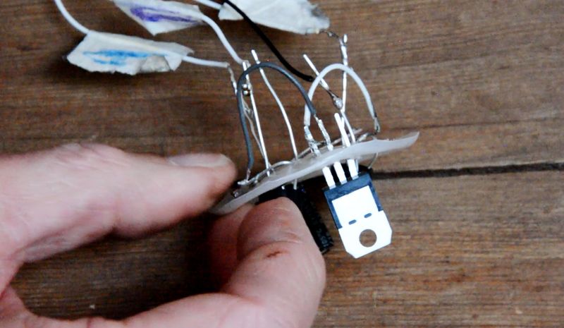
Le régulateur de tension à 3 tiges différentes : - 1 entrée - 1 commun - 1 sortie
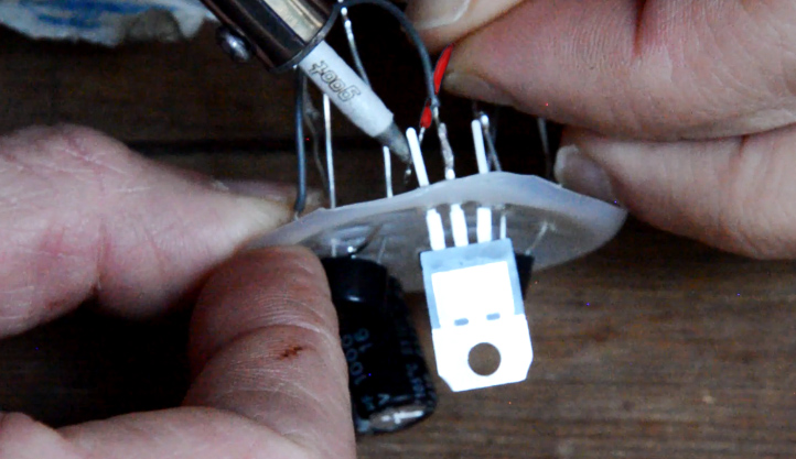
1 - Souder le pôle négatif du condensateur avec le commun du régulateur de tension. Souder le plus du condensateur à l’entrée du régulateur de tension. (image 10)
Alternative : utiliser un rehausseur de tension qui fournira une tension de sortie de 5V (USB) avec une tension d'entrée allant de 0,9 à 5V.
Étape 11 - Le circuit électrique – Raccordement du port USB
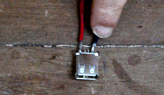
Lorsque vous posez votre connecteur sur une table avec la lamelle plastique vers le dessus, la patte de droite est votre borne positive, et la patte de gauche votre borne négative.
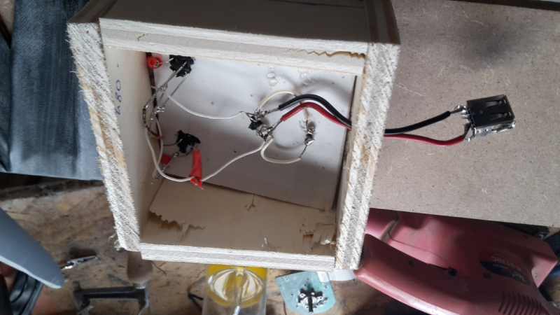
1 – Souder un fil rouge à la borne positive et un fil noir à la borne négative. Ce seront les fils de sortie de votre éolienne, auxquels vous pouvez connecter une batterie, une ampoule, etc,et dans le cas présent un port USB. (image 11)
2 – Souder le fil rouge avec la sortie du régulateur et le fil noir avec le commun du régulateur. (image 12)
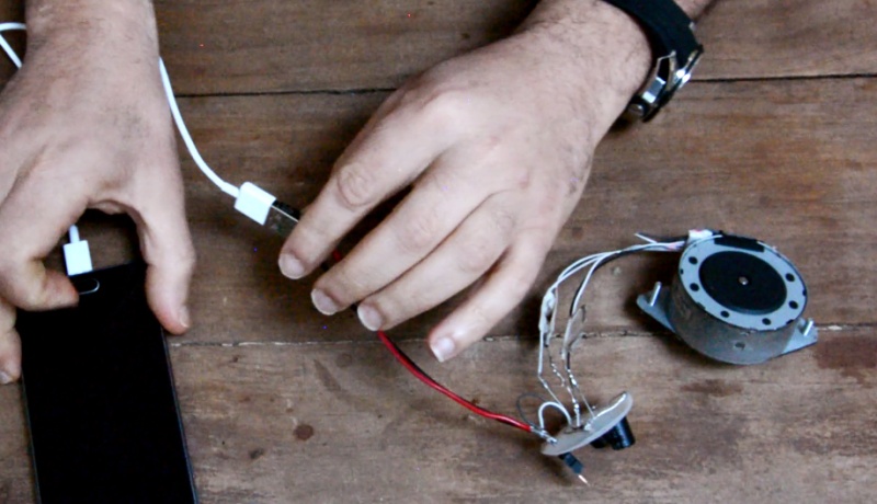
Votre circuit est prêt à fonctionner vous pouvez y brancher un téléphone, à condition qu’il y ait du vent bien sûr. (image 13)
Étape 12 - Protection du moteur
Couvrir le moteur et le circuit électrique de chambre à air : cela permettra de les protéger de la pluie ou des embruns. (image 14)
Étape 13 - Utilisation
Brancher un téléphone portable ou autre appareil comportant une connexion USB au circuit électrique et laisser recharger quelques heures. Par vent moyen compter 5 heures de charge pour une batterie de téléphone.
Notes et références
N'hésitez pas à commenter, partager, et agrémenter le tutoriel d'informations utiles à son amélioration.
Yes



 Français
 English
 Deutsch
 Español
 Italiano
 Português
Einwegoverall Kategorie III Typ 5/6
Schutzhülle mit elastischen Knöcheln, Gesicht, Manschetten und Bund zur Größenanpassung. Auch mit selbstklebender Klappe für besseren Verschluss vorne. Typ 5 & 6 mit vollständiger Übereinstimmung mit der Klassifizierung gemäß EN 14325
Material: SMS 100% Polypropylen 50 g / m2 Verfügbare Farben: weiß, Blau Größe: XL-XXL
https://einwegoverall.at/