(Page créée avec « * It is not necessary to have a solar panel, the USB charge regulator allows to recharge the cells. In this case you should not remove the bottom face of the box. ») |
(Page créée avec « Technical solution by Patrice Lelgouarch. ») |
||
| Ligne 281 : | Ligne 281 : | ||
}} | }} | ||
{{Notes | {{Notes | ||
| − | |Notes= | + | |Notes=Technical solution by Patrice Lelgouarch. |
Retrouvez la vidéo tutorielle ici : https://youtu.be/ANxmLCtGPGs | Retrouvez la vidéo tutorielle ici : https://youtu.be/ANxmLCtGPGs | ||
Version du 9 avril 2020 à 23:35
Description
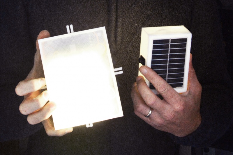
Recycle computer battery cells to create a photovoltaic lamp.
Sommaire
Sommaire
- 1 Description
- 2 Sommaire
- 3 Introduction
- 4 Video d'introduction
- 5 Étape 1 - How it works
- 6 Étape 2 - Manufacturing steps :
- 7 Étape 3 - Removing the cells from the computer battery
- 8 Étape 4 - Measuring the cells capacity
- 9 Étape 5 - Fabrication of the 3 different modules
- 10 Étape 6 - Connection of the 3 modules
- 11 Étape 7 - Making the box
- 12 Étape 8 - Fitting the modules in the box
- 13 Étape 9 - Utilisation advice
- 14 Étape 10 - Advice/Notes
- 15 Notes et références
- 16 Commentaires
Introduction
Video
CONTEXT :
Lithium is a natural ressource which is increasingly used in car batteries, phones and computers. This resource is gradually depleting. Its intensive use in batteries is mainly due to its capacity to store more energy than nickel and cadmium. As the replacement of electrical equipments and electronic devices is accelerating, these equipments become an increasingly significant source of waste (WEEE : Waste electrical and electronic equipment). At the present time, France produces 14 to 24 kg (30 to 52 pounds) of electronic waste per inhabitant per year. This rate increases by about 4% every year. In 2009, only 32% of young (18 to 34 years old) French have recycled their electronic waste. The same year, according to Eco-systèmes (https://www.ecosystem.eco), recycling 193 000 tons of WEEE between january and september would have avoided the emission of 113 000 tons of CO2.
Yet, these electronic waste have great recycling potential. One way is to reuse the lithium contained in computer battery cells. When a battery stops working, it means that one or several cells are defective but the other cells are still in working condition and therefore reusable.
We can create a separate battery from these working cells, and use it to power an electric drill, recharge a cellphone, or connect it to a solar panel and power a lamp. By connecting several cells together it is also possible to create batteries for bigger devices.Youtube
Matériaux
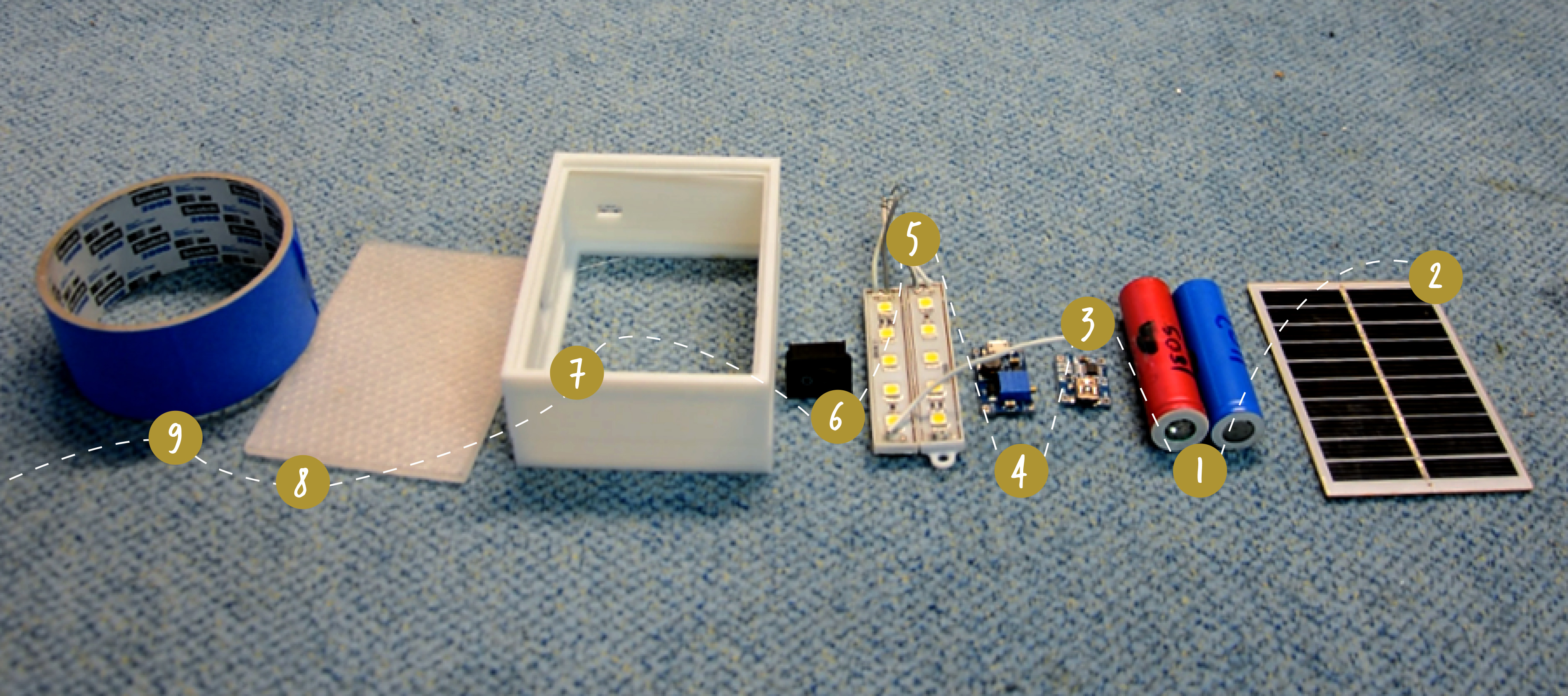
1- Computer battery
2 - Solar panel (e.g. 5V-6V mini solar panel)
3 - Charge and discharge controller (e.g. 4-8V 1A Charging Module Mini Li-ion USB Arduino)
4 - Tension regulator : DC/DC booster MT3608 (electrical component which transforms the 3.7 V current from the batteries to 12 V)
5 - LED Lamp (e.g. 2 strips of 5 SMD 5050 LEDs)
6 - Light switch (to open the circuit and cut off the light)
7 - Box (cardboard, wood, 3D printed...) with 2 openings to fit the solar panel and the light diffuser (plan to also fit the light switch and USB output)
8 - Light diffuser (for diffusing light from LEDs)
9 - Tape
Outils
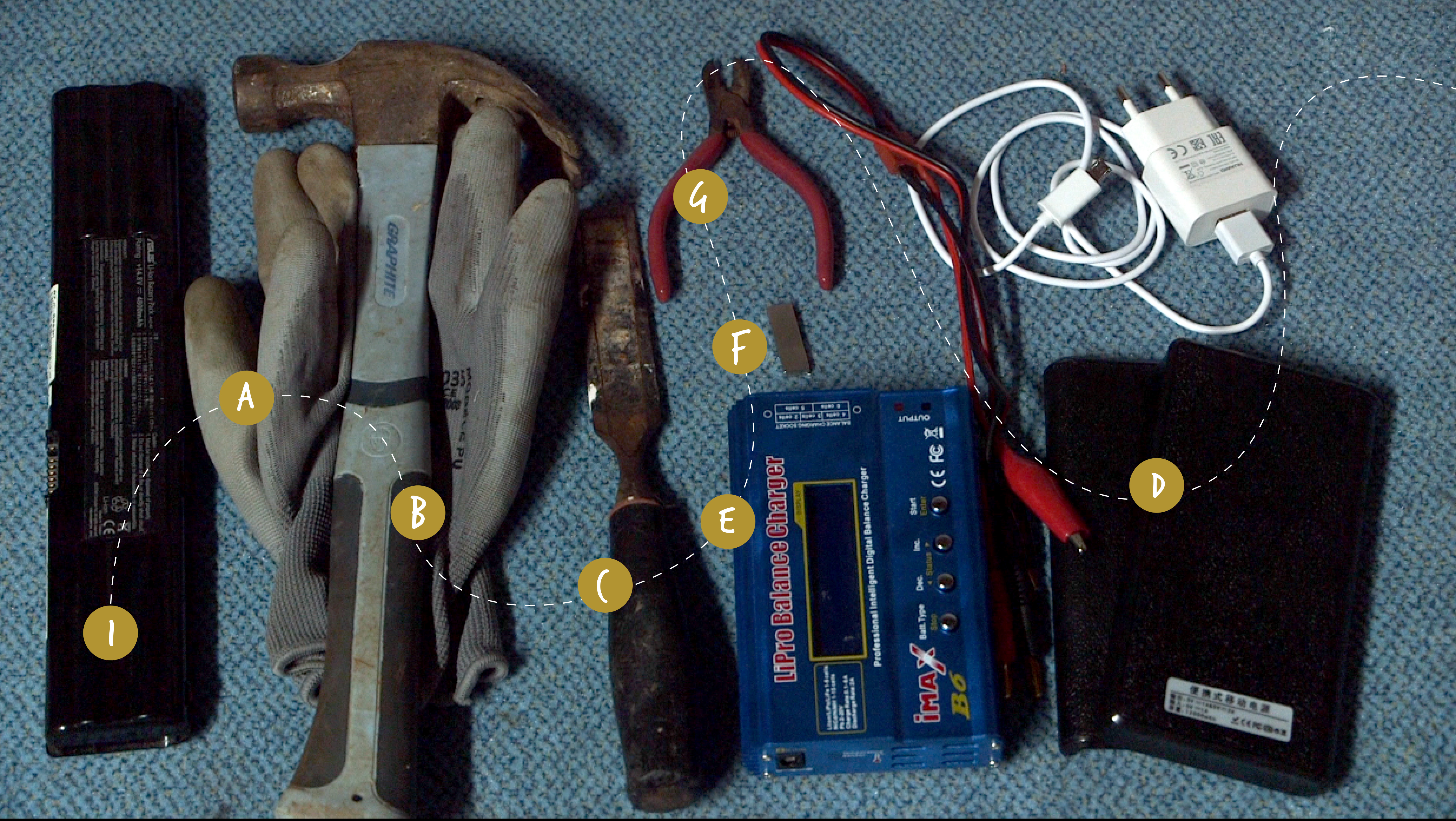
For extracting the battery cells :
a- Gloves (to avoid cutting yourself with the battery's plastic parts or with the nickel strips between the cells)
b - Hammer
c - Chisel
Power Bank (Power Bank Battery Case Box Charger Flashlight)
e - imax B6 charger
f - 2 neodymium magnets
g - Wire cutter
For making the lamp :
h - Soldering iron
i - Tin
j - Glue gun (and glue sticks)
g - Wire cutter
Étape 1 - How it works
This tutorial shows how to recover the battery cells from a computer in order to create a new battery. Powered by a solar panel or by a USB port, it will allow you to light a LED lamp.
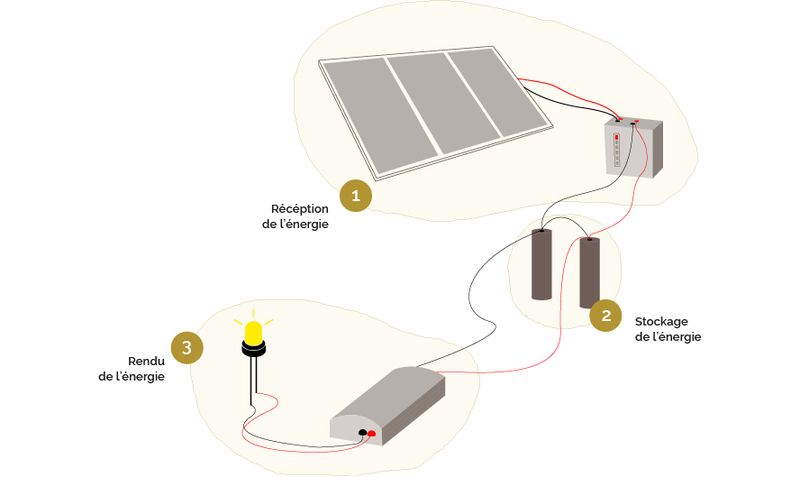
The system works around three modules:
- the energy reception module: the solar panel and its charge controller
- the energy storage module: the battery
- the module that gives back the energy: the LED lamp and its voltage regulator
Energy Receiving Module: Photovoltaic Panel & Charge Controller
The photovoltaic panel concentrates the energy of the sun. It allows to recover its energy in order to store it in the battery. But be careful, the amount of energy received by the panel is irregular depending on the time of day, the weather... It is important to install a charge/discharge regulator between the panel and the battery to protect it against overload, among other things.
Energy storage module: the battery
It is made of two lithium cells recovered from a computer. To put it in a nutshell, a battery is a bit like a box containing several batteries: each of them is a cell, a unit that supplies power to the device by electrochemical reaction.
The cells found in computers are lithium cells. They all have the same capacity to store energy, but their capacity to deliver it is different for each. To make a battery from cells it is important that they all have the same capacity to deliver energy. It is therefore necessary to measure the capacity of each cell to compose homogeneous batteries.
The module that gives back the energy: the LED lamp and its voltage regulator
Our batterie delivers a 3.7V current and our LED lamps work with 12V. So we need to transform the cell's energy from 3.7V to 12V : thanks to the voltage regulator called DC/DC booster.
A small screw on this module allows to regulate voltage. You can set it to 12V - or another voltage according to your LED's characteristics.
Étape 2 - Manufacturing steps :
1) Removing the cells from the computer battery
2) Measuring the cells capacity
3) Building the 3 modules
- solar panel + charge regulator
- battery
- LED light + charge regulator
4) Connecting the 3 modules :
- solar panel + charge regulator
- the battery
- LED light + charge regulator
5) Making the box
6) Fitting the modules in the box
Étape 3 - Removing the cells from the computer battery
1) Put on gloves to protect your hands
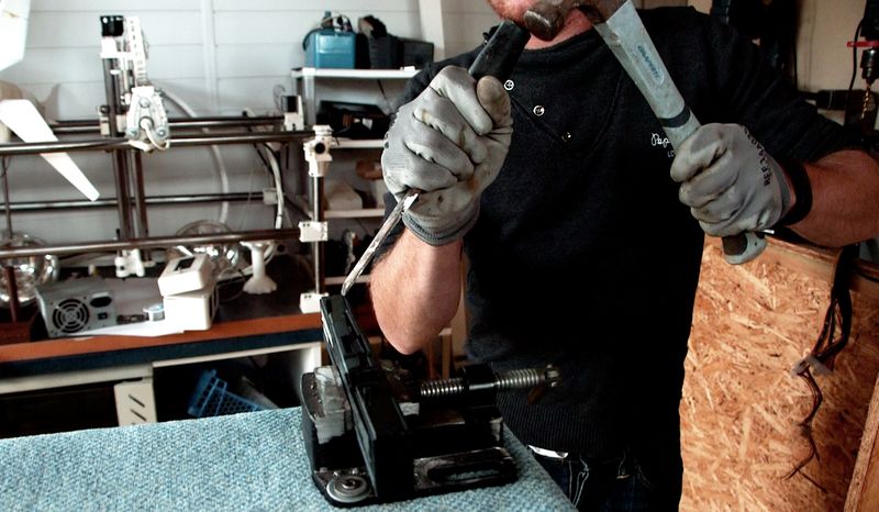
2) Fix the battery on an vice, and open it with a hammer and a chisel. (image 1)
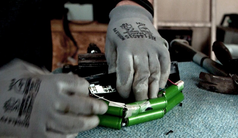
3) Isolate each cell : remove every other parts around the cells with a wire cutter (image 2)
4) Using a voltmeter (see settings on the schema), measure the cells voltage to find out which are reusable.
Note : All cells below 1V are not reusable.
Caution: If any cells have leaked (visible on the outside of the computer's battery), do not dismantle them. Lithium is toxic in high doses.
Étape 4 - Measuring the cells capacity
To measure the capacity of a cell, we have to charge it to the maximum and then discharge it. Those cells are lithium based, and lithium needs to be charged and discharged properly. Usually the maximum charge is 4,2 V and the minimum is 3V. Going over those limits will damage the cells.
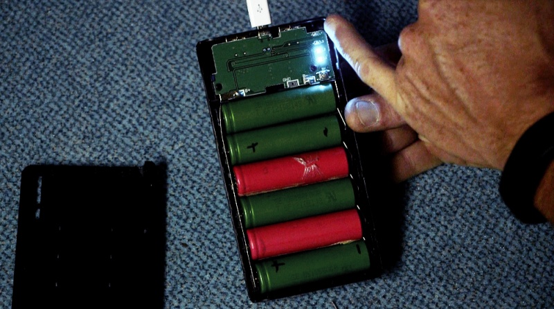
1) Use a PowerBank : it allows you to charge many cells at once with a USB port.
2) Charge the cells and wait until the charge is complete (all the lights should be on), it will be done in about 24 hours. (image 3)
The cells are charged at their maximum (4,2V), now we have to discharge them.
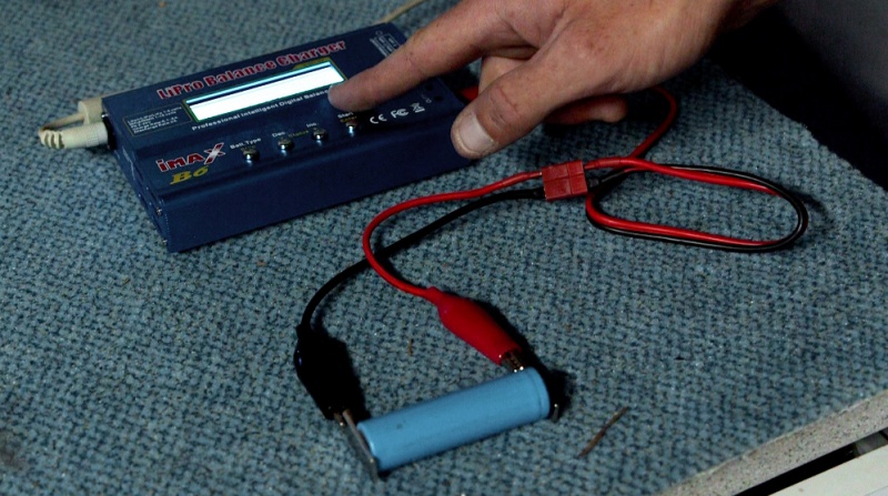
3) Use an Imax B6 : a tool that allows to discharge the cells one by one and calculate their energy delivering capacity.
4) Settings :
- voltage : it will ask you which type of cells you would like to charge, you should choose the lithium one. It will automatically regulate the discharge at 3V minimum.
- intensity : set to 1A in order to have a quick and secure discharge. In this condition, the discharge should take between 1 hour and 1 hour and half.
5) Connect the neodymium magnets to the crocodile clips, then connect to the cells, the magnet allow the current to pass between the Imax B6 and the cells. (image 4)
7) Discharge the cells until they are completely empty.
8) Note the capacity on the cell. The higher the better.
9) Sort your cells by capacity : <1000 mA, between 1000-1300, 1300-1500 and >1800 mA.
Note : It is important to do homogeneous batteries, with cells that have a similar capacity.
Étape 5 - Fabrication of the 3 different modules
Module 1 : Solar panel and charge regulator
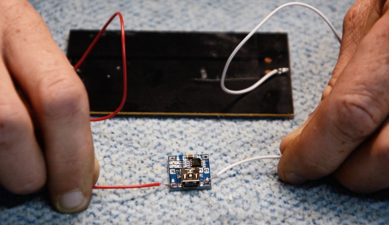
1) Use a black and a red wire, use a wire cutter to remove sleeving from the wires.
2) Solder the red wire on the (+) side of the panel and the black on on the (-) side.
The charge regulator has 2 inputs : IN- and IN+ (which are indicated on the component).
3) Solder the red wire (positive) with the IN+ input of the charge regulator and the black wire (negative) with the IN- input (image 5).
Module 2 : Battery
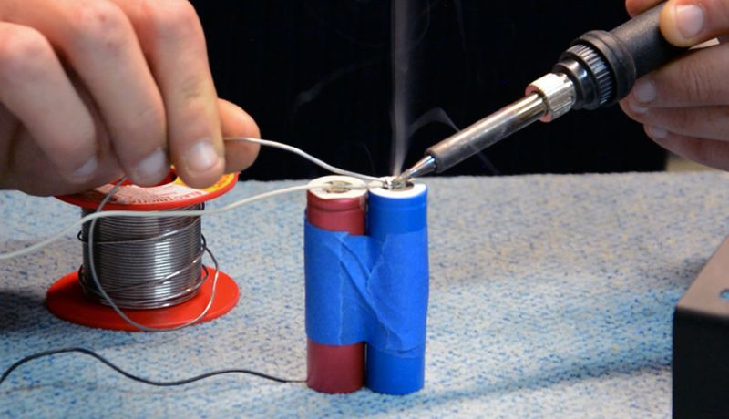
1) Tape the two cells together for easier soldering
2) Take 2 wires, one red and one black, remove sleeving on their tips on a few centimeters
3) Soldering the 2 cells in parallel : black wire to the negative poles of each cell and red wire on the positive pole of each cell. (image 6)
Caution: Isolate the welds (e.g. with tape) to avoid short-circuits .
Module 3 : Voltage regulator and LED
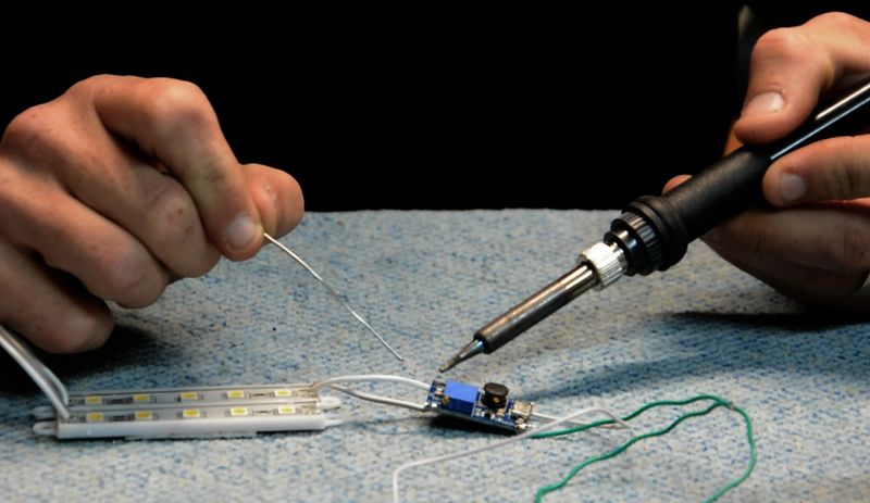
The voltage regulator has 2 inputs and 2 outputs:
Inputs : VIN + and VIN - / Outputs : OUT + and OUT -
1) Take two wires (red and black).
2) Weld the red wire with the VIN+ input of the voltage regulator and the black wire with the VIN- input.
The LED has two input wires : one positive and one negative.
Caution: Wire polarity is not indicated on the LED. In order to identify it, use an ohmmeter. The wire is positive when it displays a null value. When it displays a higher value, the wire is negative.
3) Weld the LED's positive wire to the OUT+ output of the voltage regulator and the LED's negative wire to the OUT- output. (image 7)
Étape 6 - Connection of the 3 modules
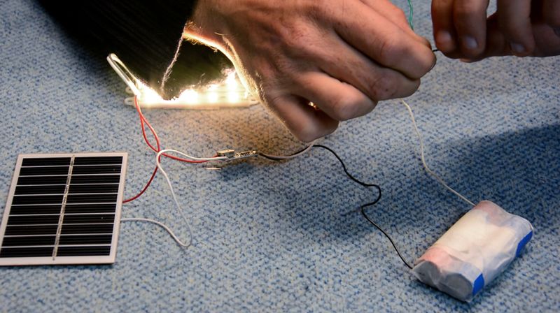
1) Connect negative cables from the battery and the converter, by twisting the wires together
2) Weld the whole to the negative pole of the regulator.
3) Repeat the same action with the positive cables of the converter and the battery, then weld the whole to the positive pole of the charge regulator. (image 8)
Note: The circuit is now closed and the light is shining.
4) Cut the positive wire connecting the regulator to the converter in order to open the circuit. We will later add the switch in series. It will be used to open and close the circuit.
Étape 7 - Making the box
1) Use a box the size of your solar panel and about 5cm deep.
2) Keep only the sides of the box, remove top and bottom.
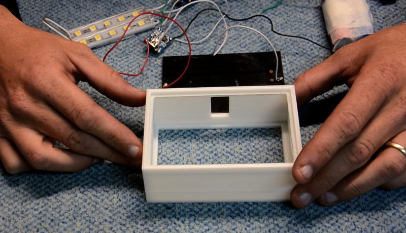
3) Pierce a hole on one side of the box to insert the switch. (image 9)
4) Pierce a second hole slightly above the place of the solar panel, in order to insert the USB output of the charge regulator.
Étape 8 - Fitting the modules in the box
1) Put the solar panel in the box first (photovoltaic side facing out)
2) Fit the light switch in its place
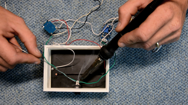
3) Weld the two tips of the positive cables from the capacitor to the switch.
4) Stick the charge regulator to the box with a glue gun, USB face towards its dedicated slot.
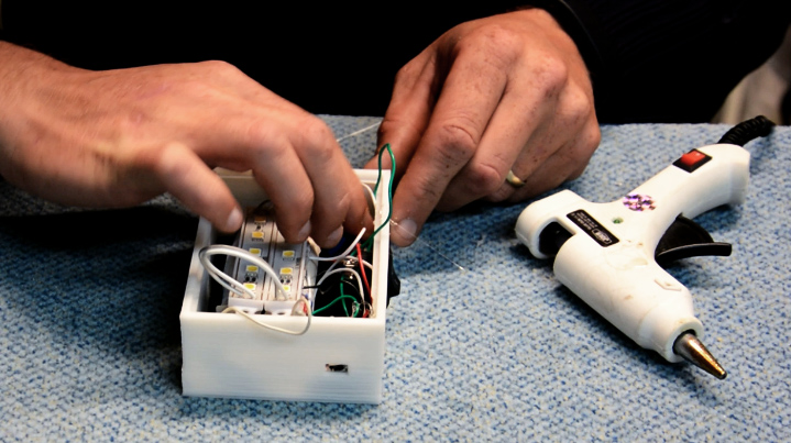
5) Stick the battery to the solar panel, stick the LED to the battery, then stick the capacitor to one of the inside faces of the box.
6) Tuck in all the wires and add the light diffuser last.
All elements are installed inside the box (image 11)
7) Switch on the switch to check everything is working.
Étape 9 - Utilisation advice
Recharge your battery in the sun during the day. Turn on the light at night.
Utilisation context
E.g. in Senegal for doing homework at night, in Morocco to keep one's shop open as long as the neighbour's who has electricity, in the desert, in transhumance...
Étape 10 - Advice/Notes
- You can shorten the cables if necessary (in order to fit the electric module inside the box) by cutting them with a wire cutter.
- It is not necessary to have a solar panel, the USB charge regulator allows to recharge the cells. In this case you should not remove the bottom face of the box.
Notes et références
Technical solution by Patrice Lelgouarch.
Retrouvez la vidéo tutorielle ici : https://youtu.be/ANxmLCtGPGs
N'hésitez pas à commenter, partager, et agrémenter le tutoriel d'informations utiles à son amélioration.
Low-tech Lab team gently invites you to check the Biblilowtech.
Published
 Français
 English
 Deutsch
 Español
 Italiano
 Português