(Page créée avec « When the piston is raised, a vacuum is created. It will attract water from the pool through the anti return system from below. The other valve is in the other direction,... ») |
(Page créée avec « When the piston is lowered, an overpressure is created, which will close the bottom check valve, and open the other valve. The water can then come out. ») |
||
| Ligne 53 : | Ligne 53 : | ||
When the piston is raised, a vacuum is created. It will attract water from the pool through the anti return system from below. The other valve is in the other direction, the water from the outlet is not sucked in. | When the piston is raised, a vacuum is created. It will attract water from the pool through the anti return system from below. The other valve is in the other direction, the water from the outlet is not sucked in. | ||
| − | + | When the piston is lowered, an overpressure is created, which will close the bottom check valve, and open the other valve. The water can then come out. | |
Ce type de pompe est appelé "pompe à refoulement". | Ce type de pompe est appelé "pompe à refoulement". | ||
Version du 14 juin 2018 à 18:01
Description
The objective is to make a manual pump to draw water from a tank for exemple.
Introduction
Matériaux
All these pieces are here in PVC for the pump : - 3 adapter 50mm-25mm - 2 couplings 50mm - 1 T 50mm-25mm
- 1 or 2 25mm elbows (depending on water outlet requirements)
- between 1 and 2 metres of 25mm tube (depending on water outlet requirements) - between 1 and 2 meters of 50mm tube - two balls over 25mm in diameter (glass balls) - 2 screws at least 50 mm long
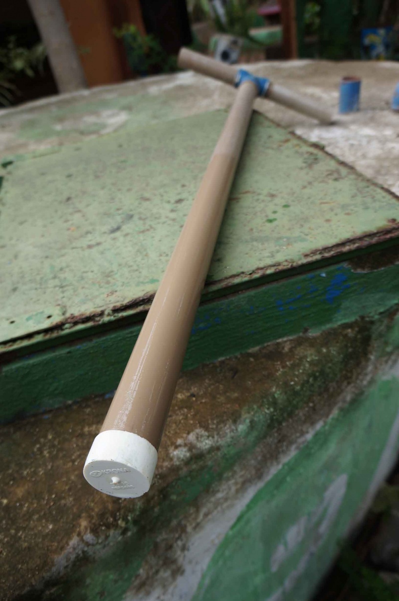
for the piston : - between 1 and 2 meters of 40mm tube - 1 T XXmm-40mm - 1 tube cap of 40mm, if possible a little wider
paint stripper (acetone type)
Outils
- Saw - Drilling machine - Screwdriver - Pvc glue - Sandpaper (glasspaper) - a cloth
Étape 1 - The principle
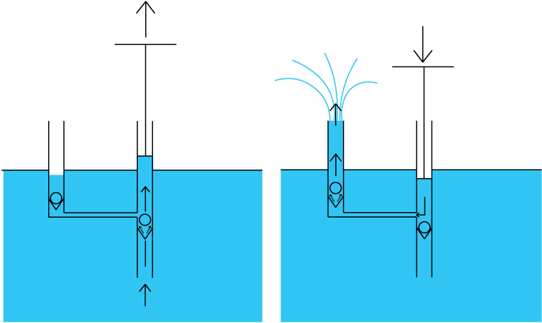
The principle of operation of this pump is very simple.
When the piston is raised, a vacuum is created. It will attract water from the pool through the anti return system from below. The other valve is in the other direction, the water from the outlet is not sucked in.
When the piston is lowered, an overpressure is created, which will close the bottom check valve, and open the other valve. The water can then come out.
Ce type de pompe est appelé "pompe à refoulement".
Étape 2 - Préparation
Sans coller les morceau, le but de cette étape est de vérifier le matériel.
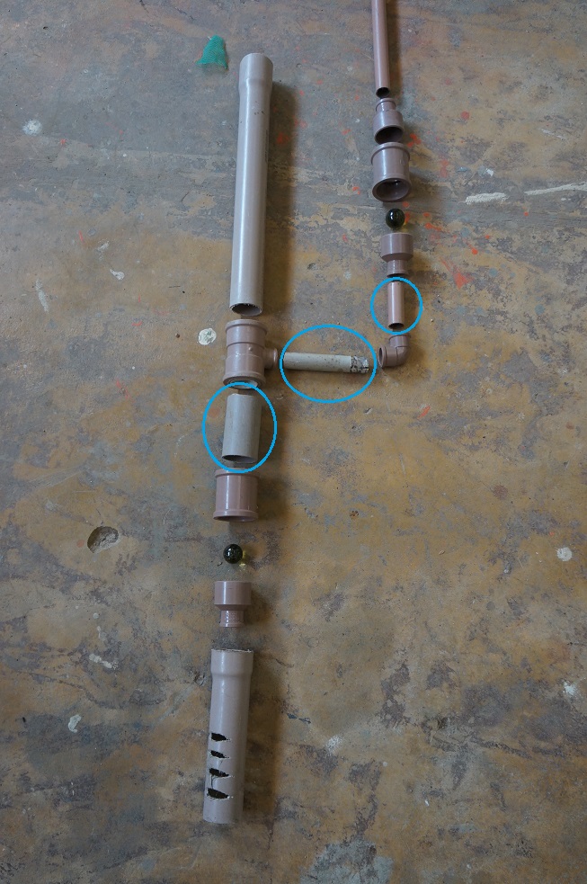
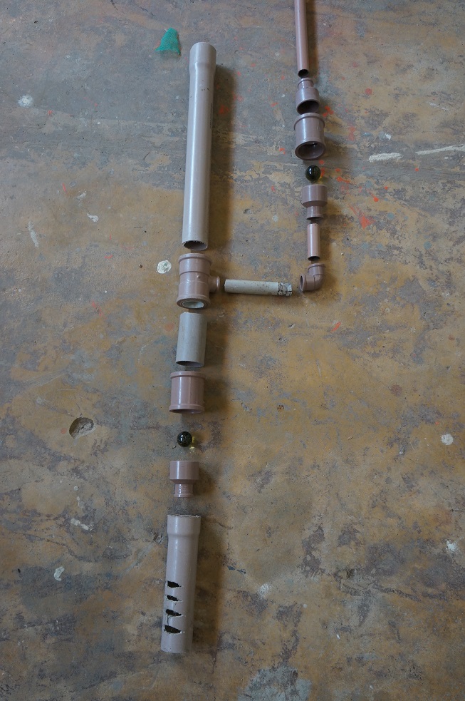
Emboitez les éléments comme sur le schéma suivant :
Vous pouvez même tester le fonctionnement.
Pour optimiser : les zones entourées en bleue doivent être les plus courtes possibles.
Étape 3 - Assemblage de la poignée
Une fois la vérification faite, l'assemblage peut commencer.
Il suffit de coller les éléments avec la colle a PVC et de bien vérifier l'étanchéité au niveau de l'embout.
Comment coller :
- Dépolir avec du papier de verre à grain fin les parties à assembler.
- Nettoyer avec un chiffon imbibé de décapant.
- Appliquer la colle à l'entrée de la partie femelle et sur la totalité de la partie mâle.
- Emboîter immédiatement à fond, sans torsion.
- Essuyer les bavures de colle.
Le temps de séchage est d'environ 1h, mais si l'eau est destinée à être consommée, il est conseillé d'attendre entre 12h et 24h pour que les solvants toxiques se dispersent.
Étape 4 - Assemblage du corps de pompe
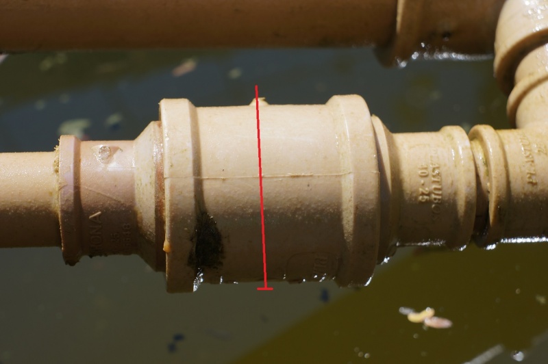
Collez tous les morceaux puis une fois sec, percez et vissez au milieu des raccord 50mm-50mm.
On peut aussi très bien clouer (voir image) en perçant avec un diamètre plus petit.
Ceci permet à la bille de se soulever suffisamment pour laisser passer l'eau, tout en l’empêchant d'aller obstruer l'autre extrémité.
/!\ Faire bien attention à ce que la bille soit du bon côté !
Étape 5 - Mise en place
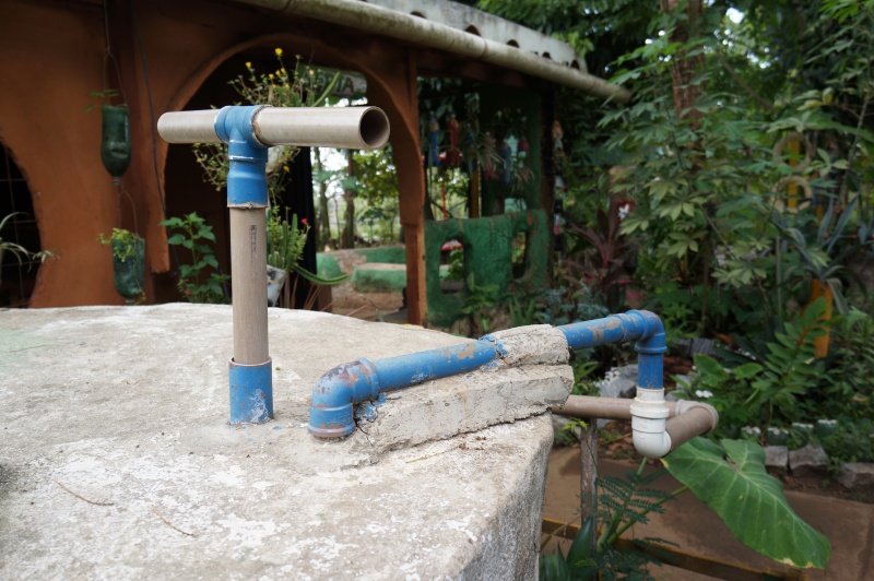
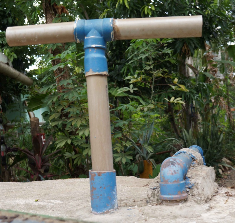
Pour une efficacité maximum, l'idéal est de sceller les tuyaux. Au SERTA, la partie non mobile est coulée dans le béton qui constitue le couvercle du réservoir.
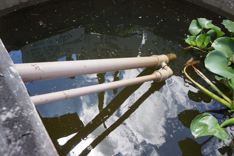
L'important est que l'allonge, par où l'eau entrera dans le circuit, ne touche pas le fond du réservoir, mais en soit cependant assez proche pour pouvoir puiser au plus profond du bassin, et que l'ensemble du système soit assez rigide pour faciliter le pompage.
Il est conseillé de positionner l'ensemble du système avant de le fixer.
Notes et références
Système installé au SERTA (Serviço de Tecnologia Alternativa) au Brésil
Améliorations : lier la pompe à une éolienne pour un pompage continu, à un vélo pour une grosse quantité.
Yes
 Français
 English
 Deutsch
 Español
 Italiano
 Português