| Ligne 162 : | Ligne 162 : | ||
2 - خازن ها | 2 - خازن ها | ||
| − | 3 - | + | 3 - تنظیم کننده ولتاژ |
4 - USB port connection | 4 - USB port connection | ||
Version du 29 mai 2018 à 15:22
Description
ساخت یک توربین بادی از موتور پله ای چاپگر
Sommaire
Sommaire
- 1 Description
- 2 Sommaire
- 3 Introduction
- 4 Video d'introduction
- 5 Étape 1 - چگونه کار می کند
- 6 Étape 2 - مراحل ساخت
- 7 Étape 3 - The wind turbine - Motor preparation
- 8 Étape 4 - The wind turbine - Motor axis
- 9 Étape 5 - The wind turbine - Blades prep
- 10 Étape 6 - The wind turbine - Aileron and base of the blades
- 11 Étape 7 - The wind turbine - Assembly
- 12 Étape 8 - The electric circuit - Rectifiers
- 13 Étape 9 - The electric circuit - Capacitor
- 14 Étape 10 - The electric circuit - Voltage Regulator or Voltage Booster
- 15 Étape 11 - The electric circuit - USB port connection
- 16 Étape 12 - Motor protection
- 17 Étape 13 - Use
- 18 Notes et références
- 19 Commentaires
Introduction
"در آفریقا، حدود 600 میلیون نفر در مناطق روستایی دسترسی به برق ندارند."
متن نوشته :
دسترسی به انرژی و به ویژه دسترسی به برق، یک پیش شرط برای توسعه اقتصادی و بهداشتی یک کشور است. در حالی که مصرف انرژی جهانی از دهه 1970 تقریبا دو برابر شده است، سهم کشورهای فقیر به طور پیوسته افزایش یافته است. امروز برآورد شده است که 2 میلیارد نفر دسترسی کافی به انرژی برای زندگی در شرایط قابل قبول ندارند و 1.6 میلیارد نفر دسترسی به برق را ندارند. این عواقب سلامت و محیط زیستی چشمگیر دارد. انرژی های تجدید پذیر مانند باد میتوانند یک راه حل باشند: توربین بادی انرژی جنبشی باد را به انرژی الکتریکی تبدیل می کند.
توربین بادی صنعتی:
توربین بادی صنعتی 2 مگاواتی تولید سالیانه حدود 4400 مگاوات ساعت دارد که نشان دهنده مصرف برق حدود 2000 نفر است. توربین های بادی صنعتی با سنسورها، قطعات متحرک، تنظیم کننده ها و قطعات مکانیکی مختلف پر می شوند. آنها در ساخت و ساز پیچیده هستند و تاثیر محیط زیستی آنها در ساخت و ساز بسیار دور از خنثی نیست. علاوه بر این، امروزه این توربین های بادی با وسایل محلی قابل تعمیر نیست.
توربین بادی کم فن آوری:
به راحتی توربین بادی کم فن آوری از مواد بازیافتی برای کمتر از 10 یورو امکان پذیر است! کاهش قدرت از توربین های بادی صنعتی، می توان آن را برای برنامه های محلی استفاده کرد: شارژ تلفن، چراغ های روشنایی، پمپ کردن یک پمپ کوچک ... برای چنین کاربردی چند وات کافی است.
بنابراین این توربین بادی می تواند بسیار مفید برای مناطق دور افتاده باشد که دسترسی به برق را ندارند و از باد مطلوب بهره مند می شوند. به عنوان مثال، در سنگال، تنها 40 درصد از جمعیت به شبکه برق در مناطق شهری متصل شده و تنها 10 درصد در مناطق روستایی. این امکان برای افراد امکان تولید برق از یک توربین بادی خود ساخته خواهد بود.
Matériaux
توربین بادی: </ u>
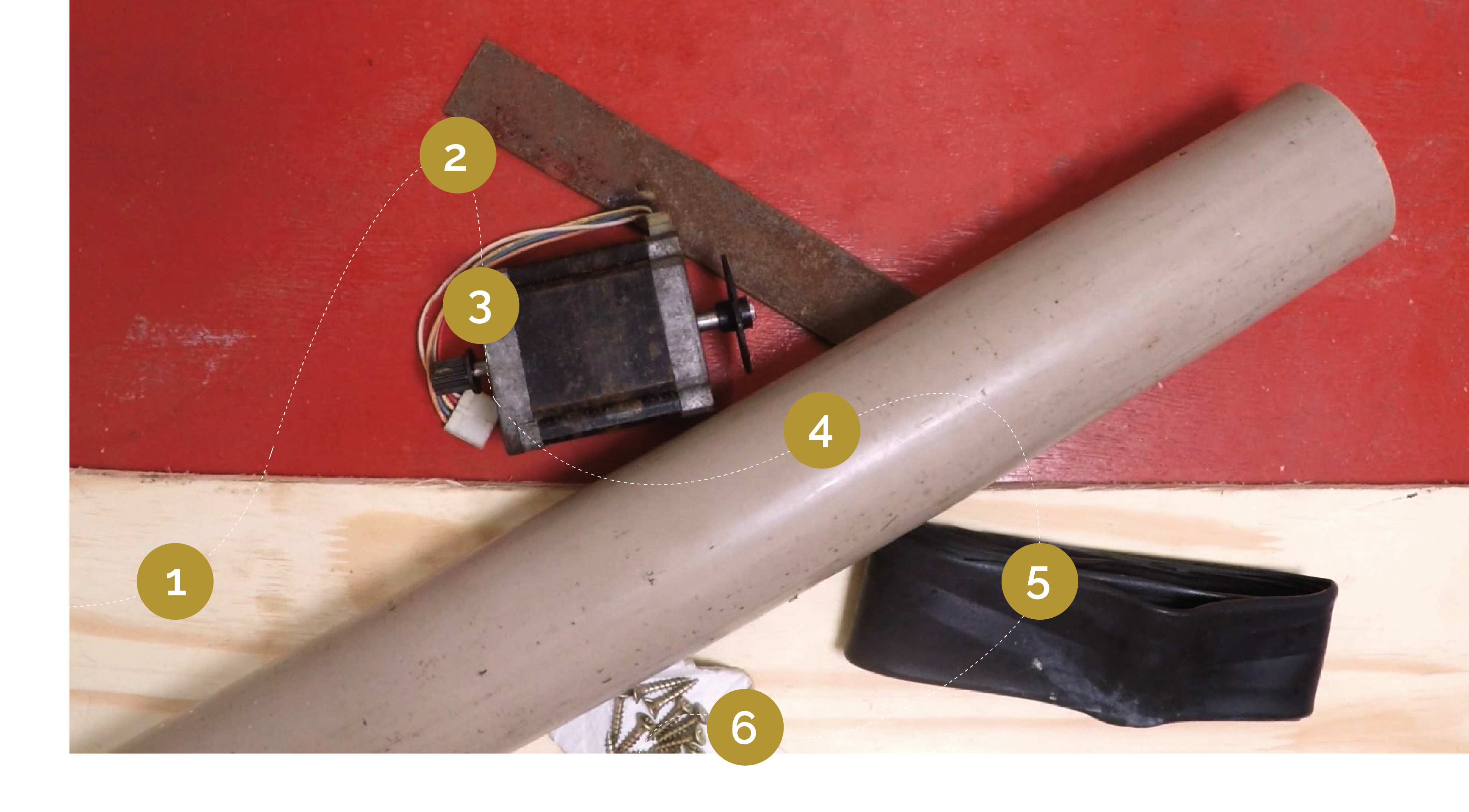
1 - هیئت مدیره چوبی (حداقل 10 میلی متر ضخامت)
2 - یک ورق آهن تخت (حداقل ضخامت 2 میلیمتر)
3 - موتور پله ای چاپگر (با پین اتصال آن)
4 - لوله پی وی سی (قطر 55 میلی متر <قطر <100 میلی متر و ضخامت 3 میلیمتر)
5 - لوله داخلی دوچرخه
6 - چوب پیچ
سیستم الکتریکی: </ u>
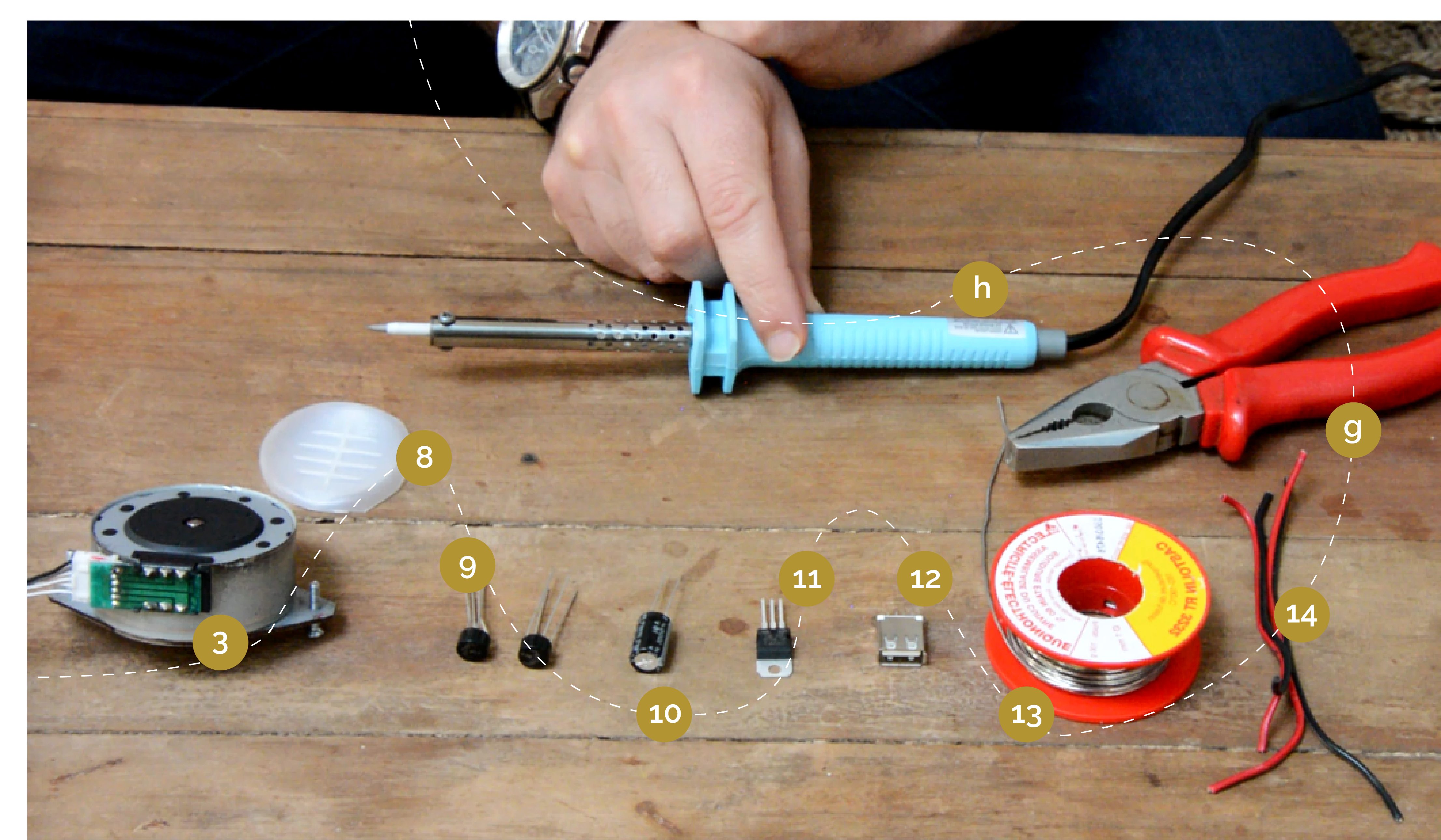
3 - موتور مرحلهنتر چاپگر
8- پشتیبانی پلاستیکی برای جابجایی عناصر مختلف سیستم (قابل بازیابی در قسمت صاف مورد چاپگر)
9 - دو ترازو ولتاژ یا پل دیود W
10 - خازن 1000μF 16V W
11 - تنظیم کننده ولتاژ W LM7805 برای تنظیم ولتاژ به 5V، ما همچنین می توانیم از LM7812 برای تنظیم ولتاژ به
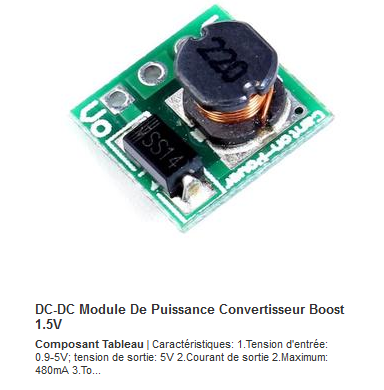
11 '- به جای تنظیم کننده ولتاژ، شما می توانید تقویت کننده ولتاژ یا DC / DC Booster یا Step Up را استفاده کنید که ولتاژ خروجی 5 ولت (USB) را با ولتاژ ورودی از 0.9 تا 5 ولت فراهم می کند.
12
-
یک
اتصال
USB
13 - قلع برای لحیم کاری
14 - سیم الکتریکی
مدل 3D این توربین بادی را پیدا کنید
Outils
توربین بادی: </ u>
a - معاون
ب - اره چوب و فلز
c - حاکم
د - پیچ گوشتی
e - ولت متر
f - کلیپ های آلتیژن
سیستم الکتریکی: </ u>
g - انبردست برش
h - آهن لحیم کاری
Étape 1 - چگونه کار می کند
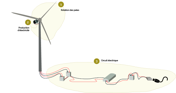
'این آموزش نشان می دهد که چگونه برای ساخت یک توربین بادی کوچک از موتور پله قدیمی از چاپگرها و یا دستگاه های کپی. این به عنوان مثال می تواند یک تلفن همراه را شارژ کند. '
1 - چرخش تیغه '
تحت تاثیر باد، پروانه، همچنین روتور نامیده می شود، شروع می شود. تیغه های خود را به نوبه خود
روتور 4 تیغه در بالای ماست قرار دارد تا باد بیشتری بگیرد.
'2 - تولید برق'
پروانه موتور موتور پمپ را درایو می کند.
با تشکر از انرژی ارائه شده توسط چرخش تیغه، موتور پله ایجاد جریان الکتریکی متناوب.
'3 - مدار الکتریکی'
مدار "رفتار" جریان خروجی موتور، به طوری که می تواند باشد برای شارژ تلفن یا دستگاه دیگر از یک پورت USB استفاده می شود.
این ساخته شده از:
- یکسو کننده هایی که "ولتاژ" را در خروجی موتور "صاف" می کنند برای داشتن یک جریان مداوم
- یک خازن به طور مداوم برق را مجددا توزیع می کند، زیرا باد یک انرژی غیر مداوم را فراهم می کند.
- تنظیم کننده ولتاژ که ولتاژ جریان الکتریکی تولید شده توسط موتور را به ولتاژ مورد نظر محدود می کند، در اینجا 5V است.
توربین باد نیاز به حداقل سرعت باد حدود 10 تا 15 کیلومتر در ساعت برای شروع چرخش آن است.
Étape 2 - مراحل ساخت
'توربین بادی'
1 - آماده سازی موتور
2 - محور موتور
3 - آماده سازی تیغه
4 - ایلئون و پایه تیغه
5 - مجمع
'مدار الکتریکی'
1 - یکسو کننده ها
2 - خازن ها
3 - تنظیم کننده ولتاژ
4 - USB port connection
Motor protection
Étape 3 - The wind turbine - Motor preparation
"Choice of the motor type"
De manière générale, plus le moteur a de pas (steps en anglais), moins la vitesse de rotation sera élevée à tension constante. Les caractéristiques techniques importantes dans le choix du moteur sont : - La tension maximale ou nominale (mesurée en volts) : Vmax - Le courant par phase (mesuré en ampères / phase) : A/ph - Le nombre de pas ou l'angle de pas (mesuré en °)
Par exemple, un moteur pas-à-pas dont l'angle est de 3.6° aura 360/3.6 = 100 pas, un moteur à 1.8° aura 360/1.8 : 200 pas... Si vous deviez choisir entre deux moteurs aux caractéristiques (Vmax et A/ph) identiques, préférez le moteur avec le plus grand nombre de pas (ici le moteur à 1.8° puisqu'il a 200 pas), il nécessitera une vitesse de rotation moins importante pour délivrer une tension satisfaisante.
The choice of the motor will also depend on the maximum voltage (Vmax). A 3V motor will deliver less power to a 50V motor at the same rotation speed. When choosing your motor (depending on what is available) consider your planned purpose and the power you need.
1 - Cut the 6 wires coming out of the stepping motor, strip them and twist them.
From here, two possible methods :
Method #1
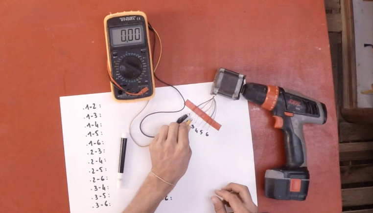
In order to know which of the 6 wires has the highest output voltage, you should test all possible motor output pairs, and select the two highest ones.
2 - Using a screwdriver, an "alternating" voltmeter and crocodile clips, test the pairs of wires. Record the voltage for each of the pairs. (image 1)
3 - Select the two wire pairs with the highest output voltage (here 10V, this may vary depending on the motor). They are the ones who will then be connected to the electric circuit of the wind turbine.
* Tip: Mark with a colored tape the two useful pairs to no longer mix them with others.
Method #2
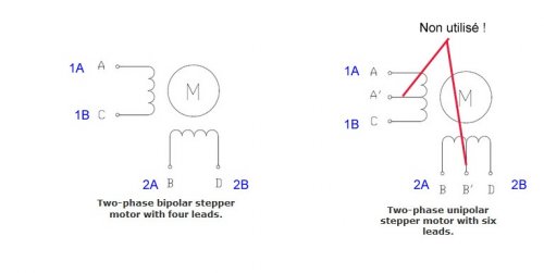
In fact the stepper motors are schematically constituted of two or four coils:
(image 2)
As shown in the picture, in the case of a 6-wire motor we will not use the midpoint. In fact, we are going to combine two coils to make one and generate more tension.
From here it's very simple :
1) Place your multimeter in ohmmeter mode, or even better in contact detection mode (you know, it makes this "BBIIIIPPPPP !!" noise when the two probes are touching).
2) First of all separate the two sets of wire for each of the coils.
For a 4-wire motor it's very simple: you take a wire on a probe, and with the other probe you touch the other wires. The one for which the meter does "BBBIIIIIPPPPP !!!" or for which the measured resistance becomes low (it depends on the motor but a wide range would be 1 to 50 ohms) you are good, you have found your coil and by elimination the two remaining wires are for the other coil.
For a 6-wire it's hardly more complex: we apply the same method to determine sets of 3 wires per coil. Then we go into ohmmeter mode and look which pair of wires per coil gives the greatest resistance ==> bingo you found the right wires for one coil, repeat the operation for the other and you are good !
Note: there are also 8-wire motors. In fact it's a 6-wire (so 4 coils) but with 4 independent coils (so pretty much like a 4-wire...). Use the same method as the 4-wire, but more times.
Étape 4 - The wind turbine - Motor axis
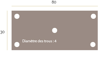
1 - Cut out a metal plate of 80x30 cm. Drill 5 holes of diameter 4.
* Tip: You can get help from diagram 1 above to cut and drill the plate.
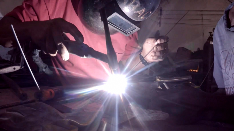
2 - Weld the metal plate to the motor axis at the plate's center hole. (image 2)
Étape 5 - The wind turbine - Blades prep
From the formula connecting the wind speed, a given surface and the power of the wind on this surface:
We can establish this formula, allowing us to calculate the length of the blades:
Where :
- L = length of the blade in m
- P = characteristic power of the motor in W
- V = wind speed in m / s (depending on the location)
Usually, the blade length must be 35 cm.
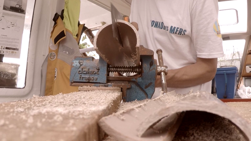
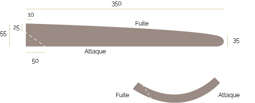
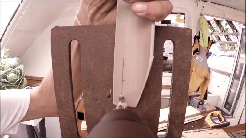
1 - Draw and cut the blades in a PVC tube. (image 3)
* Tip: You can get help from diagram 2 above to draw the shape of the blades.
Figure 3 shows the direction of the cut.
2 - Sand the edges of each blade: the leading edge must be rounded, and the trailing edge sharpened.
3 - Drill the blades: the drilling is done closer to the trailing edge so that it can be fixed flat on the plate that carries the blades. (Image 4)
Your blades are ready !
Étape 6 - The wind turbine - Aileron and base of the blades
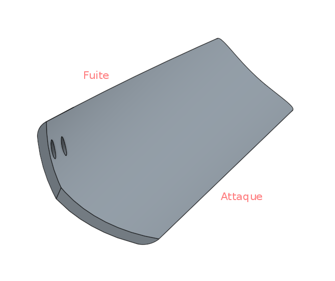
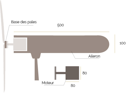
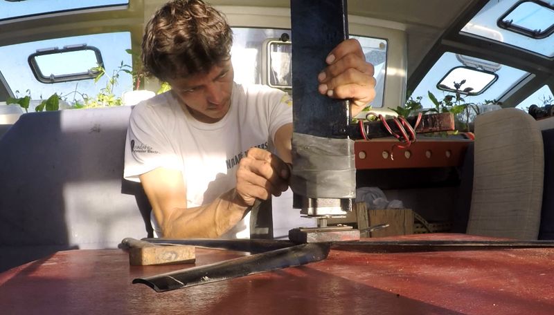
1 - In a wooden board, draw and cut the aileron. (picture 5)
* Hint: You can get help from diagram 3 above to draw the shape of the aileron.
2 - In this same board cut a square the size of your engine (here 80x80cm) which will be used to accommodate the previously cut blades and join them together. (diagram 3 - base of the baldes)
3 - On the aileron, mark the location of the engine so that it can fit into the shape. (diagram 3 - engine)
* Note: The dimensions of this part depend on the size of your engine.
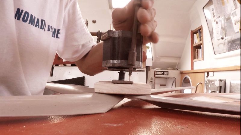
4 - Sand the edges of the aileron for better aerodynamics and better rendering. (picture 5)
Étape 7 - The wind turbine - Assembly
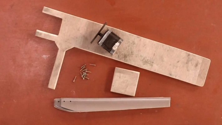
1 - Screw the blades (step 3) to their base (step 4).
2 - Screw the base of the blades onto the metal plate. Use the holes drilled in the metal plate in step 2. (image 6)
3 - Check that the angles between each blades are even.
Étape 8 - The electric circuit - Rectifiers
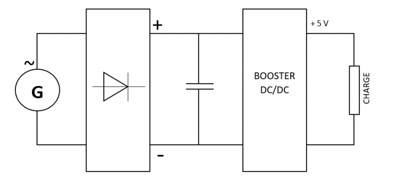
The electric circuit is shown in figure 4.
At the output of the motor, alternating current is obtained. However, to charge a battery or turn on a lamp, it is necessary to have direct current. To convert AC to DC, two rectifiers are used: they "straighten" the voltage at the output of the motor.
Each rectifier has 4 legs: The two central legs are the alternating poles of the capacitor The two outer legs are the positive and negative poles of the capacitor
* Hint : each one of these poles are marked on the rectifier's head.
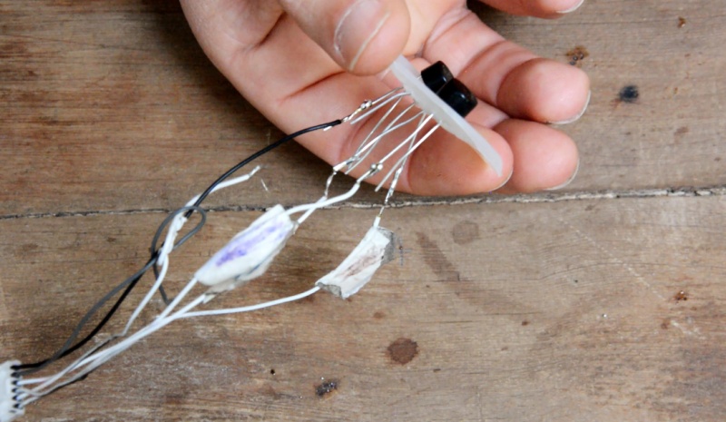
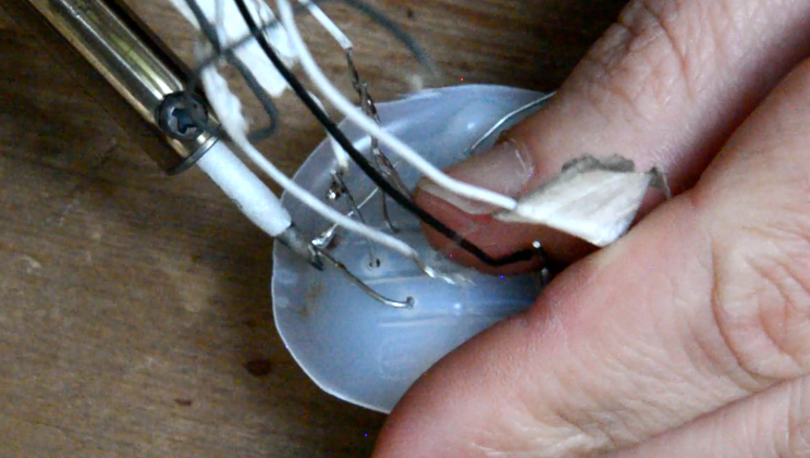
1 - Solder the voltage outputs of the stepper motor (previously selected) to the alternating inputs of each rectifier: the first pair with the alternating poles of the first rectifier, and the second pair with the alternating poles of the second rectifier. (picture 7)
*Tip: It is possible to use heat-shrink tubing to cover the connections to protect the system.
2 - Weld the negative outputs of the two rectifiers together, then weld the positive outputs of the two rectifiers together. (picture 8)
Étape 9 - The electric circuit - Capacitor
The energy supplied by the wind turbine is not constant because the wind speed varies constantly. It is therefore necessary temporarily to store the overload in order to be able to redistribute it constantly. For this purpose a capacitor is used.
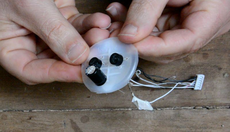
The capacitor is a polarized component: - the positive pin is the longest leg - the negative pin is the shortest leg
* Tip: It is also possible to refer to the symbol "-" written on the negative pin.
1 - Solder the negative poles to each other and then the positive poles to each other at the rectifier output. (picture 9)
* Tip: If the legs of your different components are too short to weld together, you can connect them using electrical wires.
Étape 10 - The electric circuit - Voltage Regulator or Voltage Booster
The voltage regulator allows a 5V output current.
* Note: Each controller is different, if you want a 12V output, for example, buy your controller accordingly. Here to connect a USB port we will take a 5V controller.
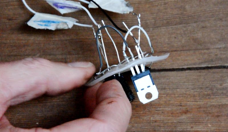
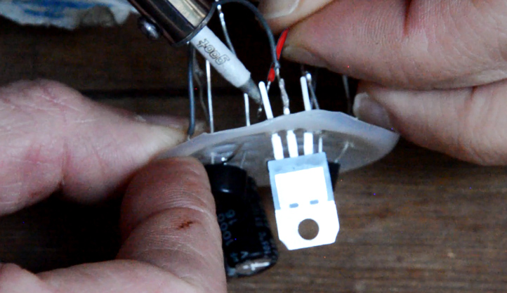
The voltage regulator has 3 different rods: - 1 input - 1 common - 1 output
1 - Solder the negative pole of the capacitor with the common rod of the voltage regulator. Solder the positive pole of the capacitor to the input of the voltage regulator. (picture 10)
Alternative: Use a voltage booster that will provide an output voltage of 5V (USB) with an input voltage ranging from 0.9 to 5V.
Étape 11 - The electric circuit - USB port connection
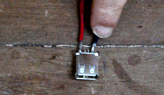
When you place your connector on a table with the plastic strip facing up, the right tab is your positive terminal, and the left tab is your negative terminal.
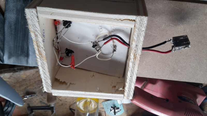
1 - Solder a red wire to the positive terminal and a black wire to the negative terminal. These will be the output wires of your wind turbine, to which you can connect a battery, a bulb, etc., and in this case a USB port. (image 11)
2 - Solder the red wire with the regulator output and the black wire with the controller common. (picture 12)
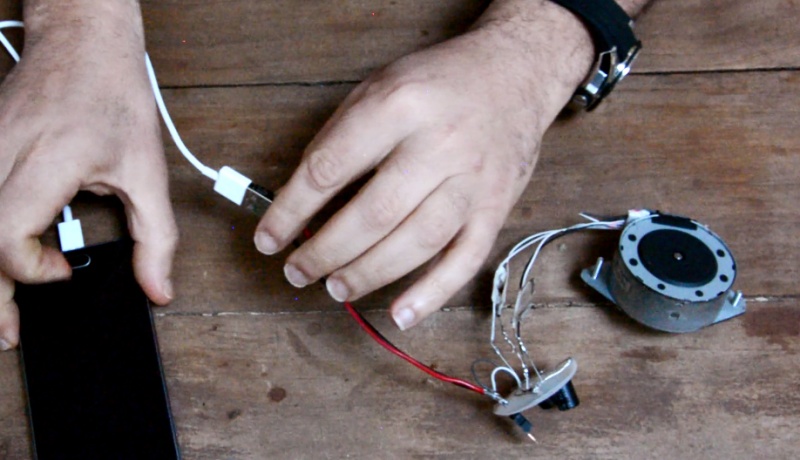
Your circuit is ready to run you can connect a phone, provided there is wind of course. (image 13)
Étape 12 - Motor protection
Cover the engine and the electrical circuit with the bike inner tube: this will protect them from rain or spray. (picture 14)
Étape 13 - Use
Connect a mobile phone or other device with a USB connection to the electrical circuit and let it charge for a few hours. In average wind, count 5 hours of charge for a phone battery.
Notes et références
Feel free to comment, share, and enhance the tutorial useful informations.
Yes



 Français
 English
 Deutsch
 Español
 Italiano
 Português