
(Page créée avec « '''Warning: '''the references in this tutorial only concern bikes with square-axle bottom brackets (which concern the majority of bikes on the market today). If your bike... ») |
(Page créée avec « Finally, you can reassemble the modified engine. ») |
||
| (75 révisions intermédiaires par le même utilisateur non affichées) | |||
| Ligne 126 : | Ligne 126 : | ||
'''Warning: '''the references in this tutorial only concern bikes with square-axle bottom brackets (which concern the majority of bikes on the market today). If your bike doesn't match, you'll need another PAS sensor. | '''Warning: '''the references in this tutorial only concern bikes with square-axle bottom brackets (which concern the majority of bikes on the market today). If your bike doesn't match, you'll need another PAS sensor. | ||
| − | + | First of all, you need to dismantle the crank, with the chainrings, on the transmission side (chainring, see image 1). | |
| − | + | Once the plate has been removed, the cover behind it must be unscrewed (see image 2). Be careful: the screw pitch may be one pitch to the left, so it must be unscrewed in the opposite direction to the usual one. | |
| − | + | Be careful not to lose the bottom bracket bearings (see image 3)! | |
| − | + | Then place the PAS sensor (a component with a metal part and a plastic part with a wire) on this shaft and screw the cover back on to secure it (see images 4 and 5). | |
| − | ''' | + | '''Warning:''' the sensor has a black plastic part, which must face outwards and the arrow indicating the direction of rotation (engraved on this same plastic part) towards the front of the bike. |
| − | + | Once the sensor has been installed, the magnetised disc needs to be placed on the pedal axle (see image 6). As the sensor is blocked by the screw, it does not move and the disc rotates as the user pedals, which makes it possible to detect whether or not the user is pedalling and at what speed. | |
| − | + | Be sure to leave a small gap between the sensor and the disc to avoid friction and thus damage to the device. | |
| − | '''Attention : ''' | + | '''Attention : '''like the sensor, the disc has a direction of assembly, you will notice arrows indicating the direction of rotation, this must correspond with the direction of pedalling as well as the direction of detection of the sensor. |
| − | + | Once the disc has been installed, the crankset needs to be reassembled. The crankset may be very sensitive (the motor turns at maximum power even when the crankset turns slowly), so you can remove a few magnetic elements from the moving part of the sensor to reduce sensitivity. | |
|Step_Picture_00=V_lo_assistance_lectrique_e21.png | |Step_Picture_00=V_lo_assistance_lectrique_e21.png | ||
|Step_Picture_01=V_lo_assistance_lectrique_e22.png | |Step_Picture_01=V_lo_assistance_lectrique_e22.png | ||
| Ligne 151 : | Ligne 151 : | ||
}} | }} | ||
{{Tuto Step | {{Tuto Step | ||
| − | |Step_Title= | + | |Step_Title=Sensor installation PAS Situation 2 |
| − | |Step_Content====='''Situation 2 :''' | + | |Step_Content====='''Situation 2:''' New-generation square-axle bottom bracket bicycle, "integrated" sensor ==== |
| − | + | Video source : https://www.youtube.com/watch?t=188&v=s1GjVU9R6Es&feature=youtu.be | |
| − | + | Tools required: Allen key, crank puller, 15 mm spanner. | |
| − | + | To start with, you'll need to remove the left-hand crank, which on this type of bike requires the use of a special tool called a "crank remover": | |
| − | Image 1 - | + | Image 1 - Unbolt the crank using the Allen key. |
| − | Image 2 - | + | Image 2 - Install the crank puller in the free thread. |
| − | Image 3 - | + | Image 3 - Using the 15 mm spanner, screw on the crank puller to release the crank. |
| − | + | This time the housing, instead of being a conventional screw, should have grooves, so the sensor must be fitted into these grooves (see image 4): | |
| − | + | Once the sensor is installed, simply reassemble the crank. | |
|Step_Picture_00=V_lo_assistance_lectrique_e27.png | |Step_Picture_00=V_lo_assistance_lectrique_e27.png | ||
|Step_Picture_01=V_lo_assistance_lectrique_e28.png | |Step_Picture_01=V_lo_assistance_lectrique_e28.png | ||
| Ligne 182 : | Ligne 182 : | ||
Solution 1 (image 1) : | Solution 1 (image 1) : | ||
| − | + | Glue the magnet to the brake lever (moving part) using a quick-setting adhesive for metal and plastic (superglue type) and place the sensor on the fixed part, the two elements should be almost in contact. | |
| − | Solution 2 : | + | Solution 2: requires the use of clamps: |
| − | + | Pass the collar through the hole in the centre of the magnet and attach it to the moving part. | |
| − | + | Fasten the sensor in the same way with a clamp around the handlebars. | |
| − | + | Once installed, the sensor detects how far away the magnet is and when it is far enough away, it cuts the electrical circuit. | |
|Step_Picture_00=V_lo_assistance_lectrique_e31.png | |Step_Picture_00=V_lo_assistance_lectrique_e31.png | ||
|Step_Picture_01=V_lo_assistance_lectrique_e32.png | |Step_Picture_01=V_lo_assistance_lectrique_e32.png | ||
}} | }} | ||
{{Tuto Step | {{Tuto Step | ||
| − | |Step_Title= | + | |Step_Title=Attaching the hoverboard wheel |
| − | |Step_Content====='''Solution 1 : | + | |Step_Content====='''Solution 1: stronger and cheaper (if you have an arc welder)'''==== |
| − | + | The metal profile must be long enough to position the hoverboard wheel in contact with the rear wheel of the bike, without it touching the saddle. | |
| − | + | Solder the motor shaft (circled in red in image 1) to one end of a mounting bar (grey in image 1). This mounting bar should preferably be a profile with an open underside to allow the motor cables to pass through. The profile can be flattened slightly to make soldering easier. | |
| − | + | Weld a bracket to the base of the stay, where it meets the seat tube, so that you can weld the attachment bar at a slight angle (see image 2), not quite perpendicular to the stay. Before welding, check that the hoverboard wheel is in contact with the bike wheel. The hoverboard wheel must rest firmly on the rear wheel of the bike to ensure that it will be driven when the electric assistance is activated (see image 3). | |
| − | ''' | + | '''Warning:''' You need to keep a small opening towards the seat tube so that you can pass the cables through and connect them to the controller. Ideally, the cables should be routed through the seat tube to avoid any problems. |
| − | ''' | + | '''Warning:''' Remember to extend the cables before attaching them if necessary. |
| − | ===='''Solution 2: Non | + | ===='''Solution 2: Non-permanent and adjustable'''==== |
| − | + | A metal tube similar to that in solution 1 can be fitted to the seatpost. Press the tube against the seatpost using metal plates and 4 bolts. Don't hesitate to deform the plates to have more surface area in contact with the seatpost and tube. If your tube is cylindrical, you can also flatten it to increase the contact area and prevent rotation. The system for attaching the wheels to the hoverboard (see photos of dismantling the hoverboard) can be used to attach the tube (both systems are available as only one wheel is used). A similar process can be used to attach the wheel to the tube. By adjusting the height of the saddle, more or less pressure can be applied to the bike wheel with the hoverboard wheel. | |
| − | + | The disadvantage of fixing to the seatpost is that the saddle will no longer be adjustable to suit the person using the bike. Depending on the proportions of the bike, it can also be fitted to the seat tube or the seat stay. | |
| − | + | The fixings should be similar to those shown in image 4. | |
| − | + | You can add a threaded rod to the shroud to adjust the pressure that the hoverboard wheel exerts on the tyre, as shown in image 5. You can weld the rod or attach it like the rest of the system. | |
|Step_Picture_00=V_lo_assistance_lectrique_e41.png | |Step_Picture_00=V_lo_assistance_lectrique_e41.png | ||
|Step_Picture_01=V_lo_assistance_lectrique_e42.png | |Step_Picture_01=V_lo_assistance_lectrique_e42.png | ||
| Ligne 224 : | Ligne 224 : | ||
}} | }} | ||
{{Tuto Step | {{Tuto Step | ||
| − | |Step_Title= | + | |Step_Title=Controller installation |
| − | |Step_Content=====''' | + | |Step_Content===== '''Wiring''' ==== |
| − | + | Reference site: [https://ebike-distribution.fr/epages/6f0ae033-c8fe-4a9d-b71d-5e69cad76385.sf/fr_FR/?ObjectPath=%2FShops%2F6f0ae033-c8fe-4a9d-b71d-5e69cad76385%2FCategories%2FMode_demplois_et_autres <u>View this link</u>] | |
| − | + | Video explanation of the controller (additional video on the same channel): https://www.youtube.com/watch?t=861&v=jiirQQv5OKU&feature=youtu.be (from 13:30 min) | |
| − | <u> | + | <u>See image 2</u> |
| − | + | First of all, locate the positive and negative poles of the power supply (Blue, 1). Above all, these poles must not be reversed. The best way to secure the connection is to solder a female XT60 connector (see image 1) (<u>see hardware section</u>). Connect the black cable to the '''-''' terminal of the XT60 and the red cable to the '''+''' terminal of the XT60. Cut the lugs already present on the cables before proceeding. | |
| − | ''' | + | '''Note:''' Check positive and negative polarity. |
| − | + | Referring to the image above, connect the PAS sensor (Violet, 5), the brushless motor power supply lines (Green, 2), the motor Hall effect sensor (Red, 3) and the brake sensor (Brown, 4). The self-adjustment lines for the Hall-effect and phase sensors (Grey, 6) are used to synchronise the motor and, if necessary, the direction of rotation. https://www.youtube.com/watch?t=861&v=jiirQQv5OKU&feature=youtu.be | |
| − | ''' | + | '''Notes :''' The direction of rotation can be reversed by inverting two phases of the motor. |
| − | ''' | + | '''Warning:''' You must check that the PAS sensor sends back a voltage, a "1", when a magnet passes in front of the sensor. If not, the use of the transistor (<u>see hardware section</u>) is necessary to invert the signal (transform the "1" into a "0"). <u>See this link from 5:44 min to 13:30 min</u> (https://www.youtube.com/watch?t=344&v=jiirQQv5OKU&feature=youtu.be<nowiki/>).See image 3 for wiring. The signal must arrive at the transistor and go back to the controller (Blue) |
| − | + | The ground is yellow in the video, the colour depends on the sensor, you need to read the datasheet to find the sensor ground. | |
===='''Isolation'''==== | ===='''Isolation'''==== | ||
| − | + | To protect the controller, it must be isolated from humidity, along with the battery. Taking into account their dimensions, a 1.5L or 2L bottle should suffice (see image 4). All you have to do is cut the bottom of the bottle a few centimetres off (4-5cm), place the neck towards the crankset to pass the cables through, and use the bottom of the bottle as a cap (slip over it to seal). | |
| − | + | LIPO batteries are sensitive to vibration. We recommend covering them with a layer of sponge. To ensure that water does not seep through the openings required for the wires, simply seal them with an insulator (silicone type). To fix the bottle to the frame (see image 5), use clamps or tape. | |
'''Optionnel :''' Vous pouvez remplacer la bouteille par une boîte en plastique spécialement conçue pour contenir une batterie. <u>[https://www.amazon.fr/Tbest-contr%C3%B4leur-Batterie-bicyclettes-%C3%A9lectriques/dp/B07D6JWQ56 Voir ce lien]</u><br /> | '''Optionnel :''' Vous pouvez remplacer la bouteille par une boîte en plastique spécialement conçue pour contenir une batterie. <u>[https://www.amazon.fr/Tbest-contr%C3%B4leur-Batterie-bicyclettes-%C3%A9lectriques/dp/B07D6JWQ56 Voir ce lien]</u><br /> | ||
| Ligne 259 : | Ligne 259 : | ||
}} | }} | ||
{{Tuto Step | {{Tuto Step | ||
| − | |Step_Title= | + | |Step_Title=Recharging the battery |
| − | |Step_Content= | + | |Step_Content=You now need to take the hoverboard's motherboard, which has been put aside, and the charging cable, which needs to be reconnected ( (2) in image 1). |
| − | + | To secure this assembly, it is possible to use available materials to make a box to store the card, leaving only the plug of the charging cable carefully reconnected to the motherboard (2) and the battery cable (1). The yellow plug must be XT60 format (see image 2) and be compatible with the XT60 male plug on the battery cable. | |
| − | ''' | + | '''Note: ''' the charging cable may need to be separated from the plastic shell of the hoverboard. All other unused cables must be inaccessible and insulated. |
|Step_Picture_00=V_lo_assistance_lectrique_e61.png | |Step_Picture_00=V_lo_assistance_lectrique_e61.png | ||
|Step_Picture_01=V_lo_assistance_lectrique_e62.png | |Step_Picture_01=V_lo_assistance_lectrique_e62.png | ||
| Ligne 270 : | Ligne 270 : | ||
{{Tuto Step | {{Tuto Step | ||
|Step_Title=Annexes | |Step_Title=Annexes | ||
| − | |Step_Content=====''' | + | |Step_Content====='''Motor modification (increased speed but higher power consumption)'''==== |
| − | + | This step is necessary if you need more speed. The operation is complicated and the regulatory limits must not be exceeded (see the section on <u>safety and legality</u>). | |
| − | + | Video sources : | |
| − | * | + | *Electronic part: <u>https://www.youtube.com/watch?v=qG8b6QkTnCU</u> |
| − | * | + | *Test part: <u>https://www.youtube.com/watch?v=P6iGSc3aIrk</u> |
| − | + | For the hoverboard motor to be able to drive the wheel correctly, its coupling must be changed from star to delta. | |
| − | + | First of all, you need to dismantle the hoverboard motor to separate the stator (fixed part with wires) and the rotor (rotating part with only magnets). | |
| − | + | The part we're interested in is the stator, the part with the windings, as these are the ones coupled in star, so we need to remove the insulation sheath (1), desolder where the windings meet (2) and separate the three main terminals of the windings connected to the phases (3), (4) and (5). | |
'''Attention :''' Il faut bien garder les fils de cuivre correspondants à la même phase ensemble, il faudra peut-être les torsader à nouveau pour bien voir apparaître les trois bornes correspondantes aux phases. Vous pouvez ressouder les brins de la même borne ensemble pour éviter qu’ils se séparent lors des futures étapes.<br /> | '''Attention :''' Il faut bien garder les fils de cuivre correspondants à la même phase ensemble, il faudra peut-être les torsader à nouveau pour bien voir apparaître les trois bornes correspondantes aux phases. Vous pouvez ressouder les brins de la même borne ensemble pour éviter qu’ils se séparent lors des futures étapes.<br /> | ||
| Ligne 291 : | Ligne 291 : | ||
}} | }} | ||
{{Tuto Step | {{Tuto Step | ||
| − | |Step_Title=Annexes | + | |Step_Title=Annexes continued |
| − | |Step_Content= | + | |Step_Content=Next, use a cutter to remove the insulating sleeves (6), (7) and (8), which are located in the centre of the motor between the shaft and the windings. |
| − | ''' | + | '''Warning: '''This step can be a little tricky because you must not cut the cables connected to the green part (Hall sensor inside the motor). |
| − | + | These internal terminals that you have discovered are the motor phases, so they are connected to the three external terminals that you disconnected earlier. | |
| − | + | You now need to identify the pairs of internal and external terminals that are connected. To do this, use a multimeter in ohmmeter mode (resistance measurement), then touch one of the external terminals with one of the probes and scan the internal terminals with the other (see image 2). | |
| − | + | When the resistance displayed is very low (note that 0L means infinity, no continuity in the circuit) or the multimeter beeps, this means that the terminals on which the probes are connected are connected. | |
| − | + | Identify the various terminals connected using upper case letters for external terminals and lower case letters for internal terminals: "A", first external terminal identified and "a", first internal terminal identified... | |
| − | Exemple : | + | Exemple : see image 3. |
| − | ''' | + | '''Caution:''' Check that the motor phase cables are not touching, otherwise your ohmmeter will detect circuit continuity between two unconnected terminals. |
| − | + | Now we need to make the delta connection: connect the windings in a special way. | |
| − | + | To do this, if you have any available, slip a piece of heat-shrink tubing over one of the terminals to cover the solder joint and insulate it electrically, then solder the terminals together as follows: | |
| − | * | + | *"a" (first internal terminal) with "B" (second external terminal) |
| − | * | + | *"b" with "C" |
| − | * | + | *"c" with "A" |
(Voir image 4). | (Voir image 4). | ||
| − | + | If you don't have heat-shrink tubing, you can use several layers of paper tape to insulate, although tubing is more recommended. | |
| − | ( | + | (This coupling is called a triangular coupling because the circuit thus created forms a triangle). |
| − | ''' | + | '''Note:''' in some cases the external terminal cannot be connected directly to the internal terminal because the wire is too short, so an intermediate wire will probably have to be added to make the connection. |
| − | + | Finally, the wires must be stored inside to prevent them getting caught in the rotor during operation. | |
| − | + | Finally, you can reassemble the modified engine. | |
|Step_Picture_00=V_lo_assistance_lectrique_e74.png | |Step_Picture_00=V_lo_assistance_lectrique_e74.png | ||
|Step_Picture_01=V_lo_assistance_lectrique_e75.png | |Step_Picture_01=V_lo_assistance_lectrique_e75.png | ||
Version actuelle datée du 9 août 2024 à 13:43

Dernière modification le 09/08/2024
Difficulté
Difficile
Durée
2 jour(s)
Coût
50 EUR (€)
Description
Modification of a bicycle to transform it into an electrically-assisted bicycle.
Sommaire
Sommaire
- 1 Description
- 2 Sommaire
- 3 Introduction
- 4 Étape 1 - Hoverboard dismantling
- 5 Étape 2 - Sensor installation PAS Situation 1
- 6 Étape 3 - Sensor installation PAS Situation 2
- 7 Étape 4 - Installation du capteur de freinage
- 8 Étape 5 - Attaching the hoverboard wheel
- 9 Étape 6 - Controller installation
- 10 Étape 7 - Recharging the battery
- 11 Étape 8 - Annexes
- 12 Étape 9 - Annexes continued
- 13 Commentaires
Introduction
In this tutorial we'll explain how to modify a conventional bike to add electric assistance. This will enable you to negotiate the steepest gradients with ease and ride faster with less effort.
Caution! The various stages involve a lot of electronics, welding and mechanics. We therefore advise you to read this tutorial carefully and to find out about the various sources provided before starting to build this electrically-assisted bike.
Legal notice
With the modifications that are going to be made, this bike will comply with European regulations for electrically-assisted bicycles. You can find them here.
It boils down to a few key points:
- The assistance must only work up to a speed of 25 km/h (it is possible to pedal faster, but without assistance).
- Motor power must not exceed 250W.
- The assistance must be activated by pedalling.
- When the user stops pedalling, the motor switches off.
- The modification must not affect safety or braking efficiency.
The bike will not be homologated, which will not pose a problem for you with the police, but you will not be insured in the event of an accident.
Matériaux
Motor + 6" hoverboard wheel: 36v
36V 4.4Ah battery
36V charger
All these elements can be found on a second-hand or used hoverboard.
A second-hand hoverboard can be found for between €50 and €100.
24V/36V 250w e-bike controller : ~€26 (Available on Aliexpress for less)
PAS sensor
Warning: Before starting/ordering anything, make sure that the gap between the frame and the crankset is at least 4.5mm, otherwise you won't be able to fit the sensor.
Hall-effect sensor to be mounted on the pedalboard + disc with magnets (usually supplied):
2 options depending on the bottom bracket :
- with square axes ("universal"): Voir ce lien ~8€
- with latest generation square axes ("integrated"): See this link ~€8
Note: unfortunately for bottom brackets with external bearings there are no PAS sensors sold individually, suitable for our tutorial. They are always adapted to the much more expensive VAE kits.
Ebike Brake sensor(to be mounted on the brake levers): ~4-7€
can be found on Ali express
Transistor
(allows you to obtain the correct signal from the pedalling sensor if it sends an inverted signal), may not be necessary depending on the PAS sensor, Reference: BS170 :~3-5€ (per 10 pieces or more)
XT60 connectors to secure the battery connection: ~€10 per 25 pairs
Open metal tube
Metal square
Clamps to secure the various components to the bike
Heat-shrink tubing (optional, to insulate against water)
Fasteners for controller, battery and wheel.
Outils
Soldering iron and arc welder
Multimeter, cutter, wire cutter
Tools for dismantling the crankset, PPE
Étape 1 - Hoverboard dismantling
Video source : https://www.youtube.com/watch?v=nikYUAnj7F0
Dismantling the hoverboard will depend on the brand and type of hoverboard. The instructions and images that follow are general but there may be details that vary.
First of all, you need to remove the plastic shell that encloses all the electronic components.
Note: Be careful with any wires connected to the plastic shells, such as the charging wire.
See image 1 a basic diagram of the inside of a hoverboard.
Unplug the cables and mark where they are connected, using marked tape if possible. In particular, keep the charging cable to one side and mark where it is connected on the motherboard.
Carefully remove the battery after disconnecting it from the motherboard and removing the wires from the central cylindrical area. Keep the battery (1) (see image 3) as it will be used to power the bike's electric assistance motor.
Caution! The battery is the most dangerous electronic component of the hoverboard. Any risk of impact, particularly with sharp objects, must be avoided. If the battery is damaged (tears, holes, etc.) or appears swollen, it must not be used, as there is a risk of explosion or flame.
The motherboard is an important element to keep to enable the battery to be recharged. You need to locate the "Charging socket" (2) on the charging cable you put aside earlier.
Next, remove the "Sensor" boards (see image 2) to gain access to the motor mountings.
At least one of the blocks of 4 screws needs to be unscrewed with an Allen key to obtain the motorised wheel that will drive the bicycle wheel (see image 4).
It is possible to keep the fixing system to make it easier to attach the wheel to the bike.


Étape 2 - Sensor installation PAS Situation 1
Situation 1 : universal square axle bottom bracket bike
PAS sensor installation video reference (from 0:00 min to 13:30 min) :https://www.youtube.com/watch?t=0&v=jiirQQv5OKU&feature=youtu.be
Warning: the references in this tutorial only concern bikes with square-axle bottom brackets (which concern the majority of bikes on the market today). If your bike doesn't match, you'll need another PAS sensor.
First of all, you need to dismantle the crank, with the chainrings, on the transmission side (chainring, see image 1).
Once the plate has been removed, the cover behind it must be unscrewed (see image 2). Be careful: the screw pitch may be one pitch to the left, so it must be unscrewed in the opposite direction to the usual one.
Be careful not to lose the bottom bracket bearings (see image 3)!
Then place the PAS sensor (a component with a metal part and a plastic part with a wire) on this shaft and screw the cover back on to secure it (see images 4 and 5).
Warning: the sensor has a black plastic part, which must face outwards and the arrow indicating the direction of rotation (engraved on this same plastic part) towards the front of the bike.
Once the sensor has been installed, the magnetised disc needs to be placed on the pedal axle (see image 6). As the sensor is blocked by the screw, it does not move and the disc rotates as the user pedals, which makes it possible to detect whether or not the user is pedalling and at what speed.
Be sure to leave a small gap between the sensor and the disc to avoid friction and thus damage to the device.
Attention : like the sensor, the disc has a direction of assembly, you will notice arrows indicating the direction of rotation, this must correspond with the direction of pedalling as well as the direction of detection of the sensor.
Once the disc has been installed, the crankset needs to be reassembled. The crankset may be very sensitive (the motor turns at maximum power even when the crankset turns slowly), so you can remove a few magnetic elements from the moving part of the sensor to reduce sensitivity.


Étape 3 - Sensor installation PAS Situation 2
Situation 2: New-generation square-axle bottom bracket bicycle, "integrated" sensor
Video source : https://www.youtube.com/watch?t=188&v=s1GjVU9R6Es&feature=youtu.be
Tools required: Allen key, crank puller, 15 mm spanner.
To start with, you'll need to remove the left-hand crank, which on this type of bike requires the use of a special tool called a "crank remover":
Image 1 - Unbolt the crank using the Allen key.
Image 2 - Install the crank puller in the free thread.
Image 3 - Using the 15 mm spanner, screw on the crank puller to release the crank.
This time the housing, instead of being a conventional screw, should have grooves, so the sensor must be fitted into these grooves (see image 4):
Once the sensor is installed, simply reassemble the crank.


Étape 4 - Installation du capteur de freinage
Pour sécuriser le freinage et s’assurer que le moteur arrête de tourner lorsque l’on freine, il faut installer des capteurs magnétiques sur les leviers de frein.
Les capteurs indiqués dans la section matériel sont simple à installer il existe deux solutions exposée dans cette vidéo : Voir ce lien
Solution 1 (image 1) :
Glue the magnet to the brake lever (moving part) using a quick-setting adhesive for metal and plastic (superglue type) and place the sensor on the fixed part, the two elements should be almost in contact.
Solution 2: requires the use of clamps:
Pass the collar through the hole in the centre of the magnet and attach it to the moving part.
Fasten the sensor in the same way with a clamp around the handlebars.
Once installed, the sensor detects how far away the magnet is and when it is far enough away, it cuts the electrical circuit.


Étape 5 - Attaching the hoverboard wheel
Solution 1: stronger and cheaper (if you have an arc welder)
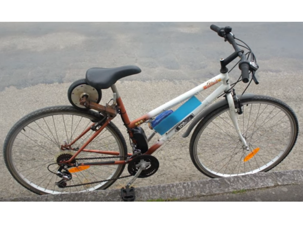
The metal profile must be long enough to position the hoverboard wheel in contact with the rear wheel of the bike, without it touching the saddle.
Solder the motor shaft (circled in red in image 1) to one end of a mounting bar (grey in image 1). This mounting bar should preferably be a profile with an open underside to allow the motor cables to pass through. The profile can be flattened slightly to make soldering easier.
Weld a bracket to the base of the stay, where it meets the seat tube, so that you can weld the attachment bar at a slight angle (see image 2), not quite perpendicular to the stay. Before welding, check that the hoverboard wheel is in contact with the bike wheel. The hoverboard wheel must rest firmly on the rear wheel of the bike to ensure that it will be driven when the electric assistance is activated (see image 3).
Warning: You need to keep a small opening towards the seat tube so that you can pass the cables through and connect them to the controller. Ideally, the cables should be routed through the seat tube to avoid any problems.
Warning: Remember to extend the cables before attaching them if necessary.
Solution 2: Non-permanent and adjustable
A metal tube similar to that in solution 1 can be fitted to the seatpost. Press the tube against the seatpost using metal plates and 4 bolts. Don't hesitate to deform the plates to have more surface area in contact with the seatpost and tube. If your tube is cylindrical, you can also flatten it to increase the contact area and prevent rotation. The system for attaching the wheels to the hoverboard (see photos of dismantling the hoverboard) can be used to attach the tube (both systems are available as only one wheel is used). A similar process can be used to attach the wheel to the tube. By adjusting the height of the saddle, more or less pressure can be applied to the bike wheel with the hoverboard wheel.
The disadvantage of fixing to the seatpost is that the saddle will no longer be adjustable to suit the person using the bike. Depending on the proportions of the bike, it can also be fitted to the seat tube or the seat stay.
The fixings should be similar to those shown in image 4.
You can add a threaded rod to the shroud to adjust the pressure that the hoverboard wheel exerts on the tyre, as shown in image 5. You can weld the rod or attach it like the rest of the system.


Étape 6 - Controller installation
Wiring
Reference site: View this link
Video explanation of the controller (additional video on the same channel): https://www.youtube.com/watch?t=861&v=jiirQQv5OKU&feature=youtu.be (from 13:30 min)
See image 2
First of all, locate the positive and negative poles of the power supply (Blue, 1). Above all, these poles must not be reversed. The best way to secure the connection is to solder a female XT60 connector (see image 1) (see hardware section). Connect the black cable to the - terminal of the XT60 and the red cable to the + terminal of the XT60. Cut the lugs already present on the cables before proceeding.
Note: Check positive and negative polarity.
Referring to the image above, connect the PAS sensor (Violet, 5), the brushless motor power supply lines (Green, 2), the motor Hall effect sensor (Red, 3) and the brake sensor (Brown, 4). The self-adjustment lines for the Hall-effect and phase sensors (Grey, 6) are used to synchronise the motor and, if necessary, the direction of rotation. https://www.youtube.com/watch?t=861&v=jiirQQv5OKU&feature=youtu.be
Notes : The direction of rotation can be reversed by inverting two phases of the motor.
Warning: You must check that the PAS sensor sends back a voltage, a "1", when a magnet passes in front of the sensor. If not, the use of the transistor (see hardware section) is necessary to invert the signal (transform the "1" into a "0"). See this link from 5:44 min to 13:30 min (https://www.youtube.com/watch?t=344&v=jiirQQv5OKU&feature=youtu.be).See image 3 for wiring. The signal must arrive at the transistor and go back to the controller (Blue)
The ground is yellow in the video, the colour depends on the sensor, you need to read the datasheet to find the sensor ground.
Isolation
To protect the controller, it must be isolated from humidity, along with the battery. Taking into account their dimensions, a 1.5L or 2L bottle should suffice (see image 4). All you have to do is cut the bottom of the bottle a few centimetres off (4-5cm), place the neck towards the crankset to pass the cables through, and use the bottom of the bottle as a cap (slip over it to seal).
LIPO batteries are sensitive to vibration. We recommend covering them with a layer of sponge. To ensure that water does not seep through the openings required for the wires, simply seal them with an insulator (silicone type). To fix the bottle to the frame (see image 5), use clamps or tape.
Optionnel : Vous pouvez remplacer la bouteille par une boîte en plastique spécialement conçue pour contenir une batterie. Voir ce lien


Étape 7 - Recharging the battery
You now need to take the hoverboard's motherboard, which has been put aside, and the charging cable, which needs to be reconnected ( (2) in image 1).
To secure this assembly, it is possible to use available materials to make a box to store the card, leaving only the plug of the charging cable carefully reconnected to the motherboard (2) and the battery cable (1). The yellow plug must be XT60 format (see image 2) and be compatible with the XT60 male plug on the battery cable.
Note: the charging cable may need to be separated from the plastic shell of the hoverboard. All other unused cables must be inaccessible and insulated.


Étape 8 - Annexes
Motor modification (increased speed but higher power consumption)
This step is necessary if you need more speed. The operation is complicated and the regulatory limits must not be exceeded (see the section on safety and legality).
Video sources :
- Electronic part: https://www.youtube.com/watch?v=qG8b6QkTnCU
- Test part: https://www.youtube.com/watch?v=P6iGSc3aIrk
For the hoverboard motor to be able to drive the wheel correctly, its coupling must be changed from star to delta.
First of all, you need to dismantle the hoverboard motor to separate the stator (fixed part with wires) and the rotor (rotating part with only magnets).
The part we're interested in is the stator, the part with the windings, as these are the ones coupled in star, so we need to remove the insulation sheath (1), desolder where the windings meet (2) and separate the three main terminals of the windings connected to the phases (3), (4) and (5).
Attention : Il faut bien garder les fils de cuivre correspondants à la même phase ensemble, il faudra peut-être les torsader à nouveau pour bien voir apparaître les trois bornes correspondantes aux phases. Vous pouvez ressouder les brins de la même borne ensemble pour éviter qu’ils se séparent lors des futures étapes.


Étape 9 - Annexes continued
Next, use a cutter to remove the insulating sleeves (6), (7) and (8), which are located in the centre of the motor between the shaft and the windings.
Warning: This step can be a little tricky because you must not cut the cables connected to the green part (Hall sensor inside the motor).
These internal terminals that you have discovered are the motor phases, so they are connected to the three external terminals that you disconnected earlier.
You now need to identify the pairs of internal and external terminals that are connected. To do this, use a multimeter in ohmmeter mode (resistance measurement), then touch one of the external terminals with one of the probes and scan the internal terminals with the other (see image 2).
When the resistance displayed is very low (note that 0L means infinity, no continuity in the circuit) or the multimeter beeps, this means that the terminals on which the probes are connected are connected.
Identify the various terminals connected using upper case letters for external terminals and lower case letters for internal terminals: "A", first external terminal identified and "a", first internal terminal identified...
Exemple : see image 3.
Caution: Check that the motor phase cables are not touching, otherwise your ohmmeter will detect circuit continuity between two unconnected terminals.
Now we need to make the delta connection: connect the windings in a special way.
To do this, if you have any available, slip a piece of heat-shrink tubing over one of the terminals to cover the solder joint and insulate it electrically, then solder the terminals together as follows:
- "a" (first internal terminal) with "B" (second external terminal)
- "b" with "C"
- "c" with "A"
(Voir image 4).
If you don't have heat-shrink tubing, you can use several layers of paper tape to insulate, although tubing is more recommended.
(This coupling is called a triangular coupling because the circuit thus created forms a triangle).
Note: in some cases the external terminal cannot be connected directly to the internal terminal because the wire is too short, so an intermediate wire will probably have to be added to make the connection.
Finally, the wires must be stored inside to prevent them getting caught in the rotor during operation.
Finally, you can reassemble the modified engine.


Published
 Français
 English
 Deutsch
 Español
 Italiano
 Português