(Page créée avec « 1.1. Building ») |
(Page créée avec « When choosing the 3.2 pump, care must be taken to use an oil pump. Such a pump may be a recovery pump and may be found on motorbikes or cars or any other machine whose ope... ») |
||
| (112 révisions intermédiaires par le même utilisateur non affichées) | |||
| Ligne 22 : | Ligne 22 : | ||
|Material=1. Solar concentrator | |Material=1. Solar concentrator | ||
| − | 1.1. | + | 1.1. Frame |
| − | * | + | *Strong wooden board, minimum size 1x2m |
| − | 1.2 | + | 1.2 Main reflector |
| − | 1.2.1. | + | 1.2.1. Main reflector support |
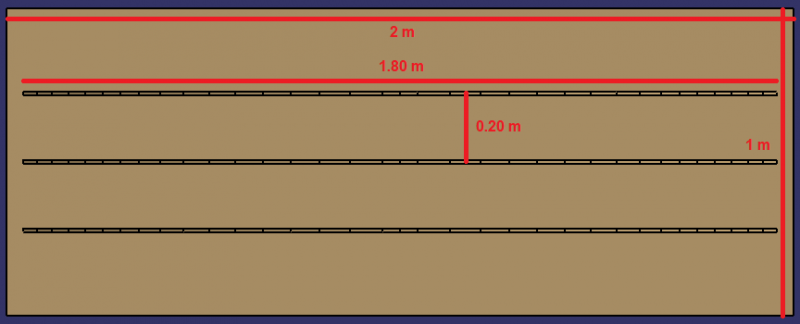
| − | * | + | *Wooden board minimum size 0.9x2m |
| − | 1.2.2. | + | 1.2.2. Mirrors |
| − | * | + | *Around 35 sheets of mirrors measuring 10x80cm |
| − | + | OR | |
| − | * | + | *Around 35 aluminium sheets, minimum size 10x80cm |
| − | * | + | *A self-adhesive mirror to cut out, approx. 0.1x1m (if possible) |
| − | 1.3. | + | 1.3. Secondary reflector |
| − | 1.3.1. | + | 1.3.1. Copper pipe and reflector support |
| − | *2 | + | *2 wooden battens, 2.4m long and 27x27mm in cross-section |
| − | * | + | *Wooden board (thickness: approx. 5mm, surface: enough to make two slabs approx. 8x8cm) |
| − | *2 | + | *2 clamps diameter 28mm |
| − | *6 | + | *6 screws |
| − | * | + | *28mm diameter copper pipe, 1m long |
| − | * | + | *2mm thick sheet metal |
| − | 1.3.2. | + | 1.3.2. Secondary reflector and copper pipe |
| − | * | + | *PVC tube: 1m long and 10cm in diameter |
| − | * | + | *Soda cans |
| − | * | + | *Black paint |
| − | 2. | + | 2. Watermaker |
| − | 2.1. | + | 2.1. Evaporation tank |
| − | 2.1.1. | + | 2.1.1. Frame |
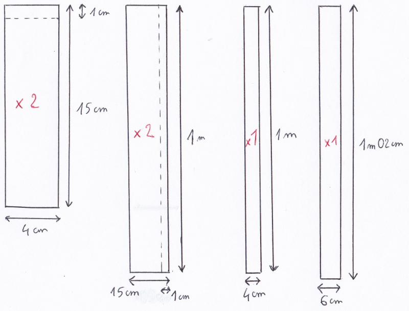
| − | *6 | + | *6 stainless steel sheets 2mm thick (2 sheets 15cmx4cm, 2 sheets 1mx1cm, 1 sheet 1mx1cm, 1 sheet 1.02mx6cm) |
| − | 2.1.2. | + | 2.1.2. Stages |
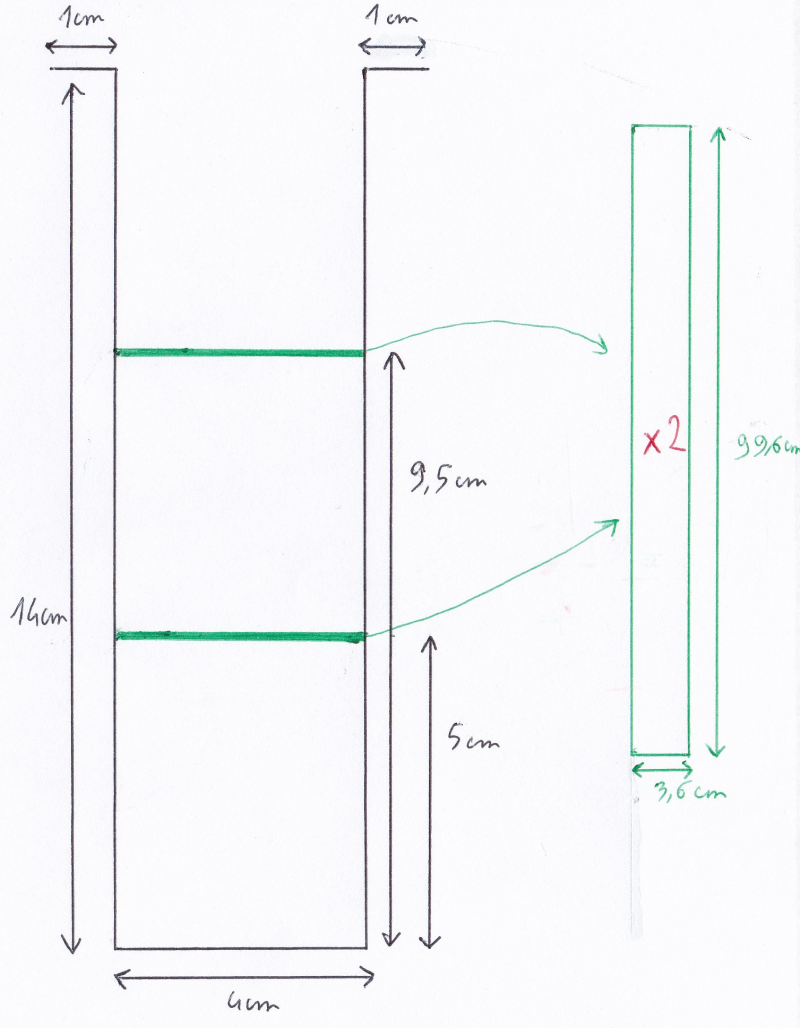
| − | *2 | + | *2 stainless steel sheets 2mm thick: 1mx3.6cm |
| − | 2.1.3. | + | 2.1.3. Copper pipe |
| − | * | + | *14mm diameter copper tube 1m long |
| − | 2.2 | + | 2.2 Condensation tank |
| − | 2.2.1. | + | 2.2.1. Frame |
| − | * | + | *2mm-thick stainless steel sheet measuring at least 200x2100mm |
| − | 2.2.2. | + | 2.2.2. Copper pipe |
| − | * | + | *14mm diameter copper tube 2,5m long |
| − | 2.2.2.1. | + | 2.2.2.1. Copper condensing coil |
| − | 2.2.2.2. | + | 2.2.2.2. Copper water inlet pipe |
| − | 2.2.2.3. | + | 2.2.2.3. Copper water outlet pipe |
| − | 2.2.3. | + | 2.2.3. Cover |
| − | *8 | + | *8 screws 6mm diameter with washers and nuts |
| − | * | + | *2mm thick stainless steel sheet: 250x250mm |
| − | 3. | + | 3. Total circuit |
| − | 3.1 | + | 3.1 Circuit-closing pipes |
| − | *20 | + | *20 rubber seals |
| − | * | + | *Valve |
| − | *5 | + | *5 flexible tubes 1m or 50 cm to close the circuit |
| − | * | + | *Any fittings |
| − | 3.2. | + | 3.2. Pump |
| − | * | + | *Oil pump |
| − | * | + | *Vegetable oil |
| − | |Tools=* | + | |Tools=* Screws |
| − | * | + | * Drills |
| − | * | + | * Saw |
| − | * | + | * Scissors |
| − | * | + | * Measuring tape |
| − | * | + | * Wood glue |
| − | * | + | * Strong glue for all materials |
| − | * | + | * Pencil |
| − | * | + | * Screwdrivers |
| − | * | + | * Welding machine |
| − | * | + | * Hacksaw |
}} | }} | ||
{{Tuto Step | {{Tuto Step | ||
|Step_Title=Nomenclature | |Step_Title=Nomenclature | ||
| − | |Step_Content=1 | + | |Step_Content=1 Solar concentrator |
| − | 1.1 | + | 1.1 Frame |
| − | 1.2 | + | 1.2 Main reflector |
| − | 1.2.1 Support | + | 1.2.1 Support for main reflector |
| − | 1.2.2 | + | 1.2.2 Mirrors |
| − | 1.3 | + | 1.3 Secondary reflector |
| − | 1.3.1 Support | + | 1.3.1 Support for secondary reflector |
| − | 1.3.2 | + | 1.3.2 Secondary reflector and copper pipe |
| − | 2 | + | 2 Watermaker |
| − | 2.1 | + | 2.1 Evaporation tank |
| − | 2.1.1 | + | 2.1.1 Frame |
| − | 2.1.2 | + | 2.1.2 Stages |
| − | 2.1.3 | + | 2.1.3 Copper pipe |
| − | 2.2 | + | 2.2 Condensation tank |
| − | 2.2.1 | + | 2.2.1 Frame |
| − | 2.2.2 | + | 2.2.2 Copper pipes |
| − | 2.2.2.1 | + | 2.2.2.1 Copper condensing coil |
| − | 2.2.2.2 | + | 2.2.2.2 Copper water inlet pipe |
| − | 2.2.2.3 | + | 2.2.2.3 Copper water outlet pipe |
| − | 2.2.3 | + | 2.2.3 Cover |
| − | 3 | + | 3 Total circuit |
| − | 3.1 | + | 3.1 Circuit closing pipes4 |
| − | 3.2 | + | 3.2 Pump |
}} | }} | ||
{{Tuto Step | {{Tuto Step | ||
| − | |Step_Title= | + | |Step_Title=General operating principle |
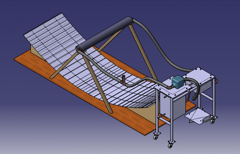
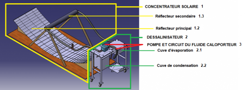
| − | |Step_Content= | + | |Step_Content=The system can be split into two sub-systems: the solar concentrator 1 and the watermaker 2. |
| − | + | In the solar concentrator 1, the sun's rays are reflected by the main reflector 1.2 and the secondary reflector 1.3 towards a copper tube 1.3.2 in which a heat transfer fluid (oil) circulates. This fluid is then heated until it boils. It circulates in a closed circuit thanks to a pump 3.2. | |
| − | + | This circuit goes through an evaporation tank 2.1 filled with dirty water, which is heated to boiling point by the heat transfer fluid. This water vapour then goes through two successive distillation stages 2.1.2 in the evaporation tank 2.1, before reaching the condensation tank 2.2 in which the water vapour is condensed by a coil 2.2.2.1 through which it travels before emerging as clean liquid water. | |
|Step_Picture_00=Dessalinisateur_solaire_autonome_L_gende_r_f_renc_e_proto_total_2.png | |Step_Picture_00=Dessalinisateur_solaire_autonome_L_gende_r_f_renc_e_proto_total_2.png | ||
}} | }} | ||
{{Tuto Step | {{Tuto Step | ||
| − | |Step_Title= | + | |Step_Title=Solar concentrator 1 - Presentation |
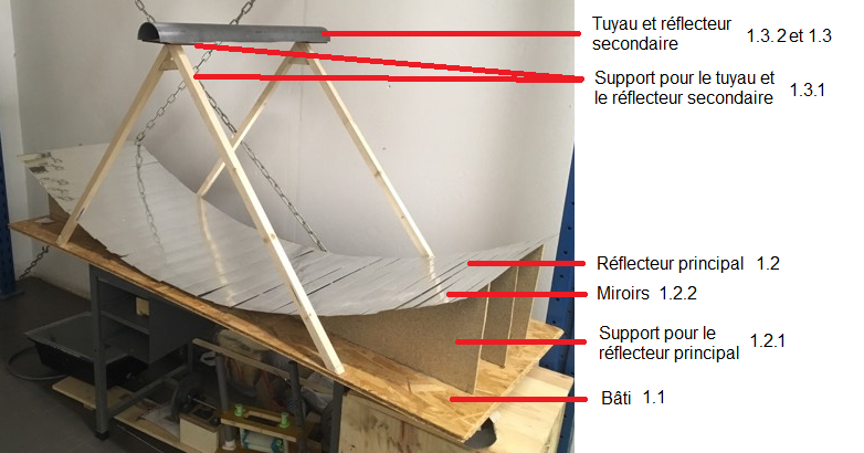
| − | |Step_Content=* | + | |Step_Content=* Name of the different parts of the solar concentrator 1 |
| − | * | + | * Material: wood |
| − | * | + | * Copper tubes |
| − | * | + | * Mirrors (or aluminium plates) |
|Step_Picture_00=Dessalinisateur_solaire_autonome_Dessalinisateur_solaire_autonome_Opensol_r_f_renc_3.png | |Step_Picture_00=Dessalinisateur_solaire_autonome_Dessalinisateur_solaire_autonome_Opensol_r_f_renc_3.png | ||
|Step_Picture_01=Ebauche_Dessalinisateur_solaire_autonome_support1.png | |Step_Picture_01=Ebauche_Dessalinisateur_solaire_autonome_support1.png | ||
}} | }} | ||
{{Tuto Step | {{Tuto Step | ||
| − | |Step_Title= | + | |Step_Title=Solar concentrator 1 - Main reflector 1.2 - Step 1 |
| − | |Step_Content= | + | |Step_Content=Step 1: Frame 1.1 |
| − | * | + | * Cut the frame 1.1 out of the strong wooden board: 1mx2m |
|Step_Picture_00=Dessalinisateur_solaire_autonome_bati1.png | |Step_Picture_00=Dessalinisateur_solaire_autonome_bati1.png | ||
}} | }} | ||
{{Tuto Step | {{Tuto Step | ||
| − | |Step_Title= | + | |Step_Title=Solar concentrator 1 - Main reflector 1.2 - Step 2 |
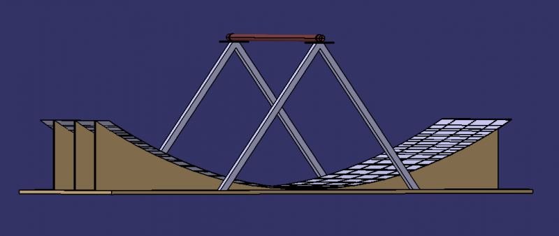
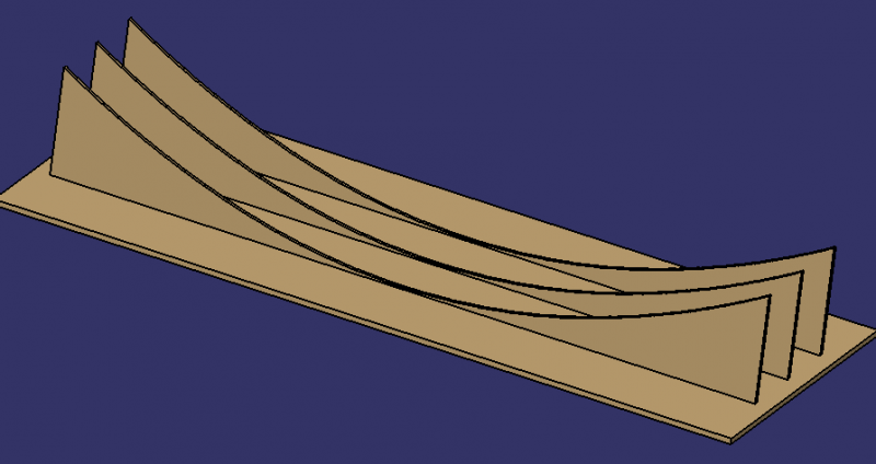
| − | |Step_Content= | + | |Step_Content=Step 2: Main reflector brackets 1.2.1 |
| − | * | + | * Cut out the 3 1.2.1 supports for the main reflector using wooden planks. |
| − | * | + | * For the parabolic shape: see dimensions in the table. |
|Step_Picture_00=Dessalinisateur_solaire_autonome_bati6.png | |Step_Picture_00=Dessalinisateur_solaire_autonome_bati6.png | ||
|Step_Picture_01=Dessalinisateur_solaire_autonome_bati_2.png | |Step_Picture_01=Dessalinisateur_solaire_autonome_bati_2.png | ||
| Ligne 181 : | Ligne 181 : | ||
}} | }} | ||
{{Tuto Step | {{Tuto Step | ||
| − | |Step_Title= | + | |Step_Title=Solar concentrator 1 - Main reflector 1.2 - Step 3 |
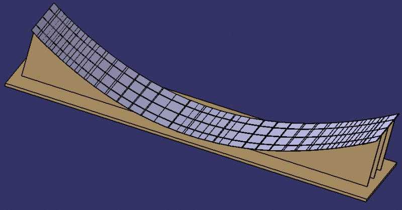
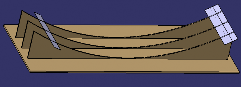
| − | |Step_Content= | + | |Step_Content=Step 3: Mirrors 1.2.2 |
| − | * | + | * Main reflector 1.2: cut the mirror plates 1.2.2 into rectangular shapes (dimensions from previous table). |
| − | * | + | * Fix the plates 1.2.2 with glue to the support 1.2.1 and check that they are correctly oriented: the sun's rays should converge towards a pipe located at a height of 80cm. |
| − | + | Note: The 1.2.2 mirror can be replaced by an aluminium plate that can be covered with self-adhesive mirror. | |
|Step_Picture_00=Dessalinisateur_solaire_autonome_bati4.png | |Step_Picture_00=Dessalinisateur_solaire_autonome_bati4.png | ||
|Step_Picture_01=Dessalinisateur_solaire_autonome_bati3.png | |Step_Picture_01=Dessalinisateur_solaire_autonome_bati3.png | ||
}} | }} | ||
{{Tuto Step | {{Tuto Step | ||
| − | |Step_Title= | + | |Step_Title=Solar concentrator 1 - Pipe support 1.3.1 - Step 1 |
| − | |Step_Content= | + | |Step_Content=Step 1: Cutting the battens |
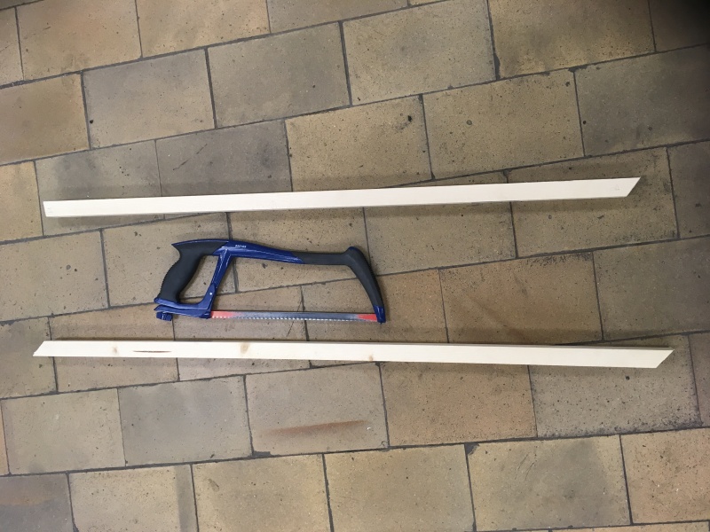
| − | * | + | * Cut the battens into four pieces approximately 65 cm long. |
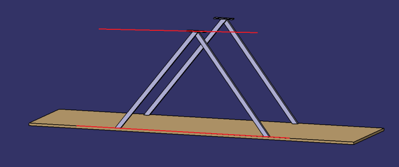
| − | * | + | * Cut inclined planes at the end of the 4 pieces so that they can be glued together 2 by 2 (see photo). After gluing, the top should be 80cm above the frame. |
| − | * | + | * Cut other inclined surfaces on the other side of the 4 pieces so that they can be fixed to the 1.1 frame. |
|Step_Picture_00=_Ebauche__Dessalinisateur_solaire_autonome_IMG_1215.jpg | |Step_Picture_00=_Ebauche__Dessalinisateur_solaire_autonome_IMG_1215.jpg | ||
|Step_Picture_01=_Ebauche__Dessalinisateur_solaire_autonome_ljhhi.png | |Step_Picture_01=_Ebauche__Dessalinisateur_solaire_autonome_ljhhi.png | ||
}} | }} | ||
{{Tuto Step | {{Tuto Step | ||
| − | |Step_Title= | + | |Step_Title=Solar concentrator 1 - Pipe support 1.3.1 - Step 2 |
| − | |Step_Content= | + | |Step_Content=Step 2: Secondary reflector support 1.3.1 and clamps |
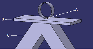
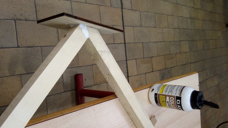
| − | * | + | * Grind the cut surfaces to make the glue more effective. |
| − | * | + | * Glue the cleats C from the previous step in pairs. Board B must be 80cm above the frame. |
| − | * | + | * Screw the two boards B to the battens C (see photo) using the clamp support A. |
|Step_Picture_00=Dessalinisateur_solaire_autonome_ABC.png | |Step_Picture_00=Dessalinisateur_solaire_autonome_ABC.png | ||
|Step_Picture_01=Ebauche_Dessalinisateur_solaire_autonome_20171003_134905.jpg | |Step_Picture_01=Ebauche_Dessalinisateur_solaire_autonome_20171003_134905.jpg | ||
}} | }} | ||
{{Tuto Step | {{Tuto Step | ||
| − | |Step_Title= | + | |Step_Title=Solar concentrator 1 - Pipe support 1.3.1 - Step 4 |
| − | |Step_Content= | + | |Step_Content=Step 4: Consolidation |
| − | * | + | * Using the off-cuts of battens, cut pieces and glue them to the supports, taking care to sand them as before, so as to consolidate the structure. |
|Step_Picture_00=_Ebauche__Dessalinisateur_solaire_autonome_IMG_1237.jpg | |Step_Picture_00=_Ebauche__Dessalinisateur_solaire_autonome_IMG_1237.jpg | ||
}} | }} | ||
{{Tuto Step | {{Tuto Step | ||
| − | |Step_Title= | + | |Step_Title=Solar concentrator 1 - Pipe support 1.3.1 - Step 5 |
| − | |Step_Content= | + | |Step_Content=Step 5: Screwing |
| − | * | + | * All that remains is to screw the two pieces of the pipe support structure 1.3.1 to the frame 1.1 from underneath the structure. |
|Step_Picture_00=_Ebauche__Dessalinisateur_solaire_autonome_support1.png | |Step_Picture_00=_Ebauche__Dessalinisateur_solaire_autonome_support1.png | ||
}} | }} | ||
{{Tuto Step | {{Tuto Step | ||
| − | |Step_Title= | + | |Step_Title=Solar concentrator 1 - Secondary reflector 1.3 - Presentation |
| − | |Step_Content= | + | |Step_Content=The secondary reflector 1.3 reflects light rays not intercepted by the copper tube 1.3.2 back onto it. It is located above the tube 1.3.2. |
|Step_Picture_00=_Ebauche__Dessalinisateur_solaire_autonome_canettes5.png | |Step_Picture_00=_Ebauche__Dessalinisateur_solaire_autonome_canettes5.png | ||
|Step_Picture_01=_Ebauche__Dessalinisateur_solaire_autonome_canettes3.png | |Step_Picture_01=_Ebauche__Dessalinisateur_solaire_autonome_canettes3.png | ||
}} | }} | ||
{{Tuto Step | {{Tuto Step | ||
| − | |Step_Title= | + | |Step_Title=Solar concentrator 1 - Main reflector 1.3 - Step 1 |
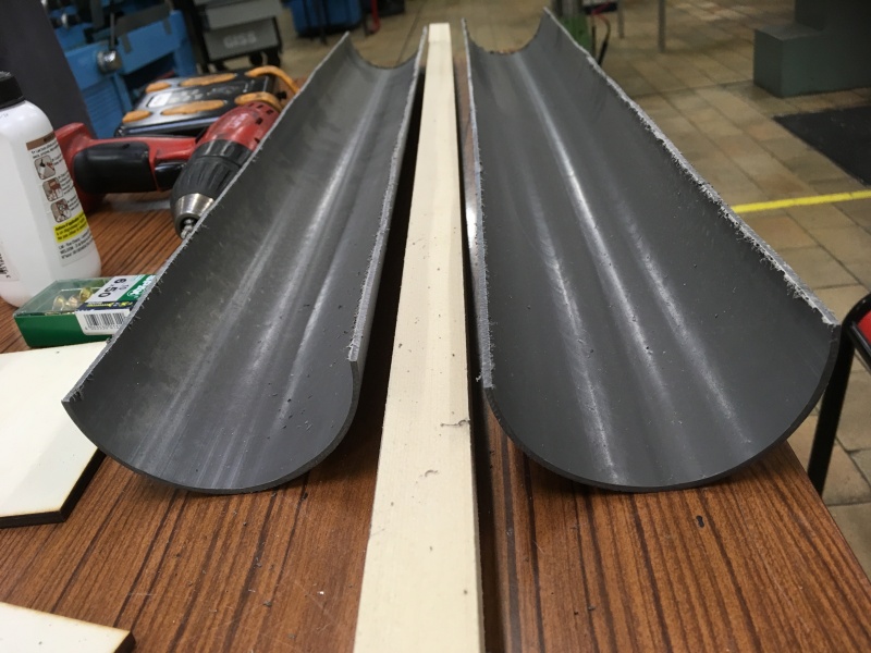
| − | |Step_Content= | + | |Step_Content=Step 1: Cutting the PVC pipe |
| − | + | The PVC tube is what supports the secondary reflector 1.3. It holds the soda cans that reflect the light rays. | |
| − | * | + | * Cut the PVC pipe in half lengthways. |
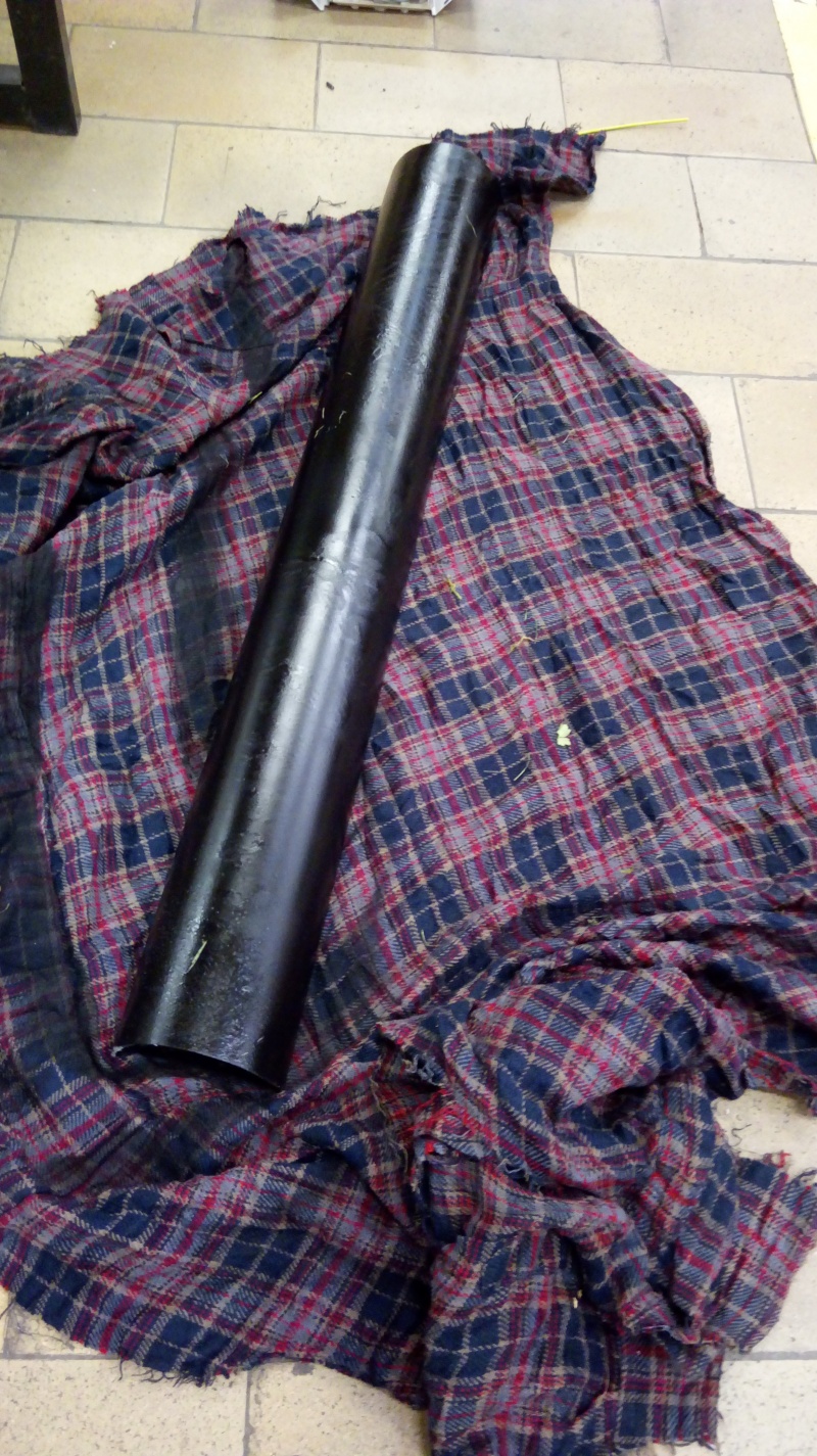
| − | * | + | * Colour the outside of the PVC pipe black with paint. |
|Step_Picture_00=_Ebauche__Dessalinisateur_solaire_autonome_IMG_1211.jpg | |Step_Picture_00=_Ebauche__Dessalinisateur_solaire_autonome_IMG_1211.jpg | ||
|Step_Picture_01=_Ebauche__Dessalinisateur_solaire_autonome_IMG_1214_1_.jpg | |Step_Picture_01=_Ebauche__Dessalinisateur_solaire_autonome_IMG_1214_1_.jpg | ||
| Ligne 244 : | Ligne 244 : | ||
}} | }} | ||
{{Tuto Step | {{Tuto Step | ||
| − | |Step_Title= | + | |Step_Title=Solar concentrator 1 - Main reflector 1.3 - Step 2 |
| − | |Step_Content= | + | |Step_Content=Step 2: Cutting and gluing the cans |
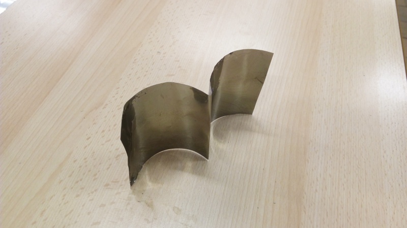
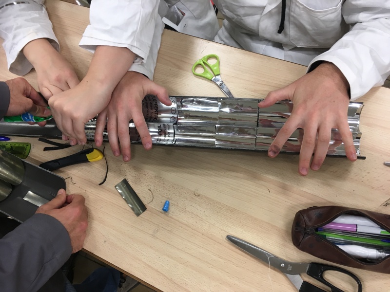
| − | + | As the cans are made of aluminium, the inside of the can proved to be a good alternative for reflecting light rays. | |
| − | * | + | * Cut the cans into rectangles 9cm wide, there are no length constraints for the other sides. |
| − | * | + | * Fold in half widthways to make two parts 4.5cm wide. |
| − | * | + | * Glue the cans into the PVC tube (they will have a rounded W shape) using strong glue. |
| − | * | + | *Note: you can stick self-adhesive mirrors in the cans to improve reflection. |
|Step_Picture_00=_Ebauche__Dessalinisateur_solaire_autonome_20171003_140552.jpg | |Step_Picture_00=_Ebauche__Dessalinisateur_solaire_autonome_20171003_140552.jpg | ||
|Step_Picture_01=_Ebauche__Dessalinisateur_solaire_autonome_IMG_1239.jpg | |Step_Picture_01=_Ebauche__Dessalinisateur_solaire_autonome_IMG_1239.jpg | ||
}} | }} | ||
{{Tuto Step | {{Tuto Step | ||
| − | |Step_Title= | + | |Step_Title=Watermaker 2 - Presentation |
| − | |Step_Content=* | + | |Step_Content=* Name of the different parts of the watermaker 2 |
| − | * | + | * Material: steel |
| − | * | + | * Copper tubes |
| − | * | + | * The condensation tank 2.2 is used to store brackish water before the evaporation tank 2.1. In this tank, the steam created by the evaporation tank 2.1 circulates in a coil 2.2.2.1. |
| − | * | + | * The evaporation vat 2.1, consisting of 2 stages 2.1.2, is used to convert brackish water into steam. The vapour created circulates through a coil 2.2.2.1 in the condensation tank 2.2 in order to cool it and convert it into a liquid state. |
| − | * | + | * Desalinated water is thus obtained. |
|Step_Picture_00=Dessalinisateur_solaire_autonome_Delta_l_gende_r_f_renc_.png | |Step_Picture_00=Dessalinisateur_solaire_autonome_Delta_l_gende_r_f_renc_.png | ||
}} | }} | ||
{{Tuto Step | {{Tuto Step | ||
| − | |Step_Title= | + | |Step_Title=Watermaker 2 - Evaporation tank 2.1 - Step 1 |
| − | |Step_Content= | + | |Step_Content=Step 1: Manufacture of the frame 2.1.1 |
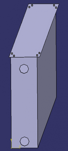
| − | * | + | * Cut the metal sheet into 6 rectangles (2 rectangles of 4cm*15cm; 2 of 1m*15cm; 1 of 1m*4cm; 1 of 6cm*1.02m). See photo. |
| − | * | + | * Fold at right angles over 1 cm as shown in the dotted lines in the photo, then make holes in the folded part to fit the screws. |
| − | * | + | * Note 1: Be careful to ensure that the walls of tank 2.1 are watertight (soldering is required)! |
| − | * | + | * Note 2: Be careful to seal between the lid and the folded walls (use a bicycle inner tube, for example, before screwing)! |
|Step_Picture_00=Ebauche_Dessalinisateur_solaire_autonome_6_plaques.png | |Step_Picture_00=Ebauche_Dessalinisateur_solaire_autonome_6_plaques.png | ||
|Step_Picture_01=Dessalinisateur_solaire_autonome_aaa.png | |Step_Picture_01=Dessalinisateur_solaire_autonome_aaa.png | ||
}} | }} | ||
{{Tuto Step | {{Tuto Step | ||
| − | |Step_Title= | + | |Step_Title=Watermaker 2 - Evaporation tank 2.1 - Step 2 |
| − | |Step_Content= | + | |Step_Content=Stage 2: Manufacture of stages 2.1.2 |
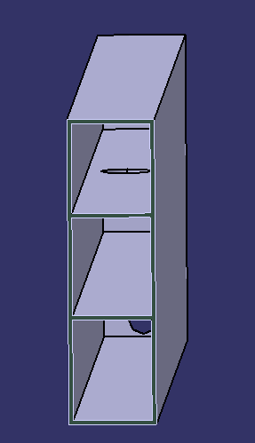
| − | * | + | * Cut out 2 trays measuring 99.6cm*3.6cm. |
| − | * | + | * Add material by welding to the side walls of vat 2.1 so that the trays can be placed on them (see photo for the height of the 2 trays and therefore the height of the 2 additions of material). |
| − | * | + | * Drill 5 cm diameter holes at one end of each tray (so that steam can circulate through all the levels) and place the 2 trays in vat 2.1 with their holes located at opposite ends. |
|Step_Picture_00=Ebauche_Dessalinisateur_solaire_autonome_Hauteur_2_plateaux.png | |Step_Picture_00=Ebauche_Dessalinisateur_solaire_autonome_Hauteur_2_plateaux.png | ||
|Step_Picture_02=Ebauche_Dessalinisateur_solaire_autonome_4.png | |Step_Picture_02=Ebauche_Dessalinisateur_solaire_autonome_4.png | ||
}} | }} | ||
{{Tuto Step | {{Tuto Step | ||
| − | |Step_Title= | + | |Step_Title=Watermaker 2 - Evaporation tank 2.1 - Step 3 |
| − | |Step_Content= | + | |Step_Content=Step 3: Making the 3 holes for the copper pipes inlet to the condensing coil 2.2.2.1 and pipe 2.2.2.3 which passes through the tank 2.1 at the bottom. |
| − | * | + | * In the 2 side walls furthest from tank 2.1: make a 14 mm diameter hole (see photo for position) in the bottom tier for pipe 2.2.2.3. |
| − | * | + | * In one of these same side walls, make a 14 mm diameter hole in the top tier (for the 2.2.2.1 pipe used to evacuate the steam). |
| − | * | + | * Solder to make a seal between the pipes and the tank! |
|Step_Picture_00=Ebauche_Dessalinisateur_solaire_autonome_5.png | |Step_Picture_00=Ebauche_Dessalinisateur_solaire_autonome_5.png | ||
|Step_Picture_01=Ebauche_Dessalinisateur_solaire_autonome_Cuve_evap_1.png | |Step_Picture_01=Ebauche_Dessalinisateur_solaire_autonome_Cuve_evap_1.png | ||
| Ligne 301 : | Ligne 301 : | ||
}} | }} | ||
{{Tuto Step | {{Tuto Step | ||
| − | |Step_Title= | + | |Step_Title=Watermaker 2 - Evaporation tank 2.2 - Step 1 |
| − | |Step_Content= | + | |Step_Content=Step 1: Cutting the sheet into 5 sections |
| − | * | + | * 5-sided cut-out |
| − | * | + | * Base side: 200x200mm |
| − | * 4 | + | * 4 side panels: 200x355mm |
| − | * | + | * Fold the side faces on top to create edges for screwing on a lid (using the same system as in the previous step). |
| − | * | + | * Welding of the base and 4 sides |
|Step_Picture_00=_Ebauche__Dessalinisateur_solaire_autonome_Capture_d_e_cran_2017-11-26_a_14.49.13.png | |Step_Picture_00=_Ebauche__Dessalinisateur_solaire_autonome_Capture_d_e_cran_2017-11-26_a_14.49.13.png | ||
|Step_Picture_01=Ebauche_Dessalinisateur_solaire_autonome_Capture_d_e_cran_2017-11-08_a_22.36.25.png | |Step_Picture_01=Ebauche_Dessalinisateur_solaire_autonome_Capture_d_e_cran_2017-11-08_a_22.36.25.png | ||
}} | }} | ||
{{Tuto Step | {{Tuto Step | ||
| − | |Step_Title= | + | |Step_Title=Watermaker 2 - Evaporation tank 2.2 - Step 2 |
| − | |Step_Content= | + | |Step_Content=Step 2 : Holes |
| − | + | Four holes to drill: | |
| − | * | + | * A water inlet hole from the storage tank, which accommodates a flow regulator (such as a flush valve for autonomous use, but a simple manual valve may suffice). This hole should be at the top of the tank. The 2.2.2.2 pipe passes through it. |
| − | * | + | * An outlet hole for brackish water preheated by steam condensation, at the bottom of tank 2.2, towards evaporation tank 2.1. Pipe 2.2.2.3 passes through. |
| − | * | + | * A steam inlet hole from the evaporation tank 2.1 (condensation coil inlet 2.2.2.1), located below the water level in tank 2.2. |
| − | * | + | * A drinking water outlet hole (condensing coil outlet 2.2.2.1), lower than the previous hole. |
| − | * | + | * Note: these holes must be made in relation to the other parts of the prototype (particularly for the condensation coil 2.2.2.1 where it is advisable to manufacture it before drilling the holes: see next step). |
| − | * | + | * See image where the brackish water outlet hole is not shown (water inlet: top right and the 2 ends of the condensing coil 2.2.2.1 are top left and bottom right). |
|Step_Picture_00=Ebauche_Dessalinisateur_solaire_autonome_Capture_d_e_cran_2017-11-26_a_14.35.54.png | |Step_Picture_00=Ebauche_Dessalinisateur_solaire_autonome_Capture_d_e_cran_2017-11-26_a_14.35.54.png | ||
}} | }} | ||
{{Tuto Step | {{Tuto Step | ||
| − | |Step_Title= | + | |Step_Title=Watermaker 2 - Evaporation tank 2.2 - Step 3 |
| − | |Step_Content= | + | |Step_Content=Step 3: Condensing coil 2.2.2.1 (where the steam condenses) |
| − | * | + | * Surround the copper tube 2.2.2.1 with a rigid spring (to obtain a circular shape). |
| − | * | + | * If the copper is not annealed, heat it to a red colour and immerse it in cold water immediately. |
| − | * | + | * Then give it a helical shape by gradually winding it around a cylinder. |
| − | * | + | * Insert the coil 2.2.2.1 into the tank 2.2 through the 2 holes previously made. |
|Step_Picture_00=_Ebauche__Dessalinisateur_solaire_autonome_15.png | |Step_Picture_00=_Ebauche__Dessalinisateur_solaire_autonome_15.png | ||
|Step_Picture_01=_Ebauche__Dessalinisateur_solaire_autonome_11.png | |Step_Picture_01=_Ebauche__Dessalinisateur_solaire_autonome_11.png | ||
| Ligne 341 : | Ligne 341 : | ||
}} | }} | ||
{{Tuto Step | {{Tuto Step | ||
| − | |Step_Title= | + | |Step_Title=Watermaker 2 - Evaporation tank 2.2 - Step 4 |
| − | |Step_Content= | + | |Step_Content=Step 4: Lid 2.3 of tank 2.2 |
| − | * | + | * Drill at least 8 holes on the edges of the tank 2.2 for the screws that will secure the lid 2.3. |
| − | * | + | * Cut a 250x250mm square sheet to serve as the lid 2.3 and drill at least 8 holes in it corresponding to the previous ones so that the lid can be screwed on; |
| − | * | + | * A bicycle inner tube can be inserted between the edges of tank 2.2 and lid 2.3 for a better seal. |
}} | }} | ||
{{Tuto Step | {{Tuto Step | ||
| − | |Step_Title= | + | |Step_Title=Total circuit 3 |
| − | |Step_Content= | + | |Step_Content=Now that the two main parts have been built, all that remains is to close the circuit where the heat transfer fluid will circulate! The heat transfer fluid is vegetable oil, which will be circulated by the 3.2 pump built into the circuit. 3.1 pipes should be well insulated (insulate yourself if necessary) and flexible (so you can move the prototype easily). |
}} | }} | ||
{{Tuto Step | {{Tuto Step | ||
| − | |Step_Title= | + | |Step_Title=Pump 3.2 |
| − | |Step_Content= | + | |Step_Content=When choosing the 3.2 pump, care must be taken to use an oil pump. Such a pump may be a recovery pump and may be found on motorbikes or cars or any other machine whose operation requires an oil pump. |
}} | }} | ||
{{Notes | {{Notes | ||
Version actuelle datée du 5 juillet 2024 à 16:29
Description
A project by engineering students to build a low-tech solar watermaker to help disadvantaged communities.
Sommaire
Sommaire
- 1 Description
- 2 Sommaire
- 3 Introduction
- 4 Étape 1 - Nomenclature
- 5 Étape 2 - General operating principle
- 6 Étape 3 - Solar concentrator 1 - Presentation
- 7 Étape 4 - Solar concentrator 1 - Main reflector 1.2 - Step 1
- 8 Étape 5 - Solar concentrator 1 - Main reflector 1.2 - Step 2
- 9 Étape 6 - Solar concentrator 1 - Main reflector 1.2 - Step 3
- 10 Étape 7 - Solar concentrator 1 - Pipe support 1.3.1 - Step 1
- 11 Étape 8 - Solar concentrator 1 - Pipe support 1.3.1 - Step 2
- 12 Étape 9 - Solar concentrator 1 - Pipe support 1.3.1 - Step 4
- 13 Étape 10 - Solar concentrator 1 - Pipe support 1.3.1 - Step 5
- 14 Étape 11 - Solar concentrator 1 - Secondary reflector 1.3 - Presentation
- 15 Étape 12 - Solar concentrator 1 - Main reflector 1.3 - Step 1
- 16 Étape 13 - Solar concentrator 1 - Main reflector 1.3 - Step 2
- 17 Étape 14 - Watermaker 2 - Presentation
- 18 Étape 15 - Watermaker 2 - Evaporation tank 2.1 - Step 1
- 19 Étape 16 - Watermaker 2 - Evaporation tank 2.1 - Step 2
- 20 Étape 17 - Watermaker 2 - Evaporation tank 2.1 - Step 3
- 21 Étape 18 - Watermaker 2 - Evaporation tank 2.2 - Step 1
- 22 Étape 19 - Watermaker 2 - Evaporation tank 2.2 - Step 2
- 23 Étape 20 - Watermaker 2 - Evaporation tank 2.2 - Step 3
- 24 Étape 21 - Watermaker 2 - Evaporation tank 2.2 - Step 4
- 25 Étape 22 - Total circuit 3
- 26 Étape 23 - Pump 3.2
- 27 Commentaires
Introduction
L'EauTech is a project run by six students from the Ecole Centrale de Lille in collaboration with the Gold Of Bengal association. The aim of the project is to build a low-tech solar watermaker, based on two projects already carried out at the Ecole Centrale de Lille: the Opensol project, which created a low-tech solar concentrator, and the Delta project, which created a low-tech watermaker.
You can find and download a summary of this tutorial in PDF format by clicking on this link: https://drive.google.com/open?id=1aqvStMdIfSuhj4bioxSa0Zk8wiuJO1vL .
Matériaux
1. Solar concentrator
1.1. Frame
- Strong wooden board, minimum size 1x2m
1.2 Main reflector
1.2.1. Main reflector support
- Wooden board minimum size 0.9x2m
1.2.2. Mirrors
- Around 35 sheets of mirrors measuring 10x80cm
OR
- Around 35 aluminium sheets, minimum size 10x80cm
- A self-adhesive mirror to cut out, approx. 0.1x1m (if possible)
1.3. Secondary reflector
1.3.1. Copper pipe and reflector support
- 2 wooden battens, 2.4m long and 27x27mm in cross-section
- Wooden board (thickness: approx. 5mm, surface: enough to make two slabs approx. 8x8cm)
- 2 clamps diameter 28mm
- 6 screws
- 28mm diameter copper pipe, 1m long
- 2mm thick sheet metal
1.3.2. Secondary reflector and copper pipe
- PVC tube: 1m long and 10cm in diameter
- Soda cans
- Black paint
2. Watermaker
2.1. Evaporation tank
2.1.1. Frame
- 6 stainless steel sheets 2mm thick (2 sheets 15cmx4cm, 2 sheets 1mx1cm, 1 sheet 1mx1cm, 1 sheet 1.02mx6cm)
2.1.2. Stages
- 2 stainless steel sheets 2mm thick: 1mx3.6cm
2.1.3. Copper pipe
- 14mm diameter copper tube 1m long
2.2 Condensation tank
2.2.1. Frame
- 2mm-thick stainless steel sheet measuring at least 200x2100mm
2.2.2. Copper pipe
- 14mm diameter copper tube 2,5m long
2.2.2.1. Copper condensing coil 2.2.2.2. Copper water inlet pipe 2.2.2.3. Copper water outlet pipe
2.2.3. Cover
- 8 screws 6mm diameter with washers and nuts
- 2mm thick stainless steel sheet: 250x250mm
3. Total circuit
3.1 Circuit-closing pipes
- 20 rubber seals
- Valve
- 5 flexible tubes 1m or 50 cm to close the circuit
- Any fittings
3.2. Pump
- Oil pump
- Vegetable oil
Outils
- Screws
- Drills
- Saw
- Scissors
- Measuring tape
- Wood glue
- Strong glue for all materials
- Pencil
- Screwdrivers
- Welding machine
- Hacksaw
Étape 1 - Nomenclature
1 Solar concentrator
  1.1 Frame
  1.2 Main reflector
     1.2.1 Support for main reflector
     1.2.2 Mirrors
  1.3 Secondary reflector
     1.3.1 Support for secondary reflector
     1.3.2 Secondary reflector and copper pipe
2 Watermaker
  2.1 Evaporation tank
     2.1.1 Frame
     2.1.2 Stages
     2.1.3 Copper pipe
  2.2 Condensation tank
     2.2.1 Frame
     2.2.2 Copper pipes
        2.2.2.1 Copper condensing coil
        2.2.2.2 Copper water inlet pipe
        2.2.2.3 Copper water outlet pipe
  2.2.3 Cover
3 Total circuit
  3.1 Circuit closing pipes4
  3.2 Pump
Étape 2 - General operating principle
The system can be split into two sub-systems: the solar concentrator 1 and the watermaker 2.
In the solar concentrator 1, the sun's rays are reflected by the main reflector 1.2 and the secondary reflector 1.3 towards a copper tube 1.3.2 in which a heat transfer fluid (oil) circulates. This fluid is then heated until it boils. It circulates in a closed circuit thanks to a pump 3.2.
This circuit goes through an evaporation tank 2.1 filled with dirty water, which is heated to boiling point by the heat transfer fluid. This water vapour then goes through two successive distillation stages 2.1.2 in the evaporation tank 2.1, before reaching the condensation tank 2.2 in which the water vapour is condensed by a coil 2.2.2.1 through which it travels before emerging as clean liquid water.
Étape 3 - Solar concentrator 1 - Presentation
- Name of the different parts of the solar concentrator 1
- Material: wood
- Copper tubes
- Mirrors (or aluminium plates)
Étape 4 - Solar concentrator 1 - Main reflector 1.2 - Step 1
Step 1: Frame 1.1
- Cut the frame 1.1 out of the strong wooden board: 1mx2m
Étape 5 - Solar concentrator 1 - Main reflector 1.2 - Step 2
Step 2: Main reflector brackets 1.2.1
- Cut out the 3 1.2.1 supports for the main reflector using wooden planks.
- For the parabolic shape: see dimensions in the table.
Étape 6 - Solar concentrator 1 - Main reflector 1.2 - Step 3
Step 3: Mirrors 1.2.2
- Main reflector 1.2: cut the mirror plates 1.2.2 into rectangular shapes (dimensions from previous table).
- Fix the plates 1.2.2 with glue to the support 1.2.1 and check that they are correctly oriented: the sun's rays should converge towards a pipe located at a height of 80cm.
Note: The 1.2.2 mirror can be replaced by an aluminium plate that can be covered with self-adhesive mirror.
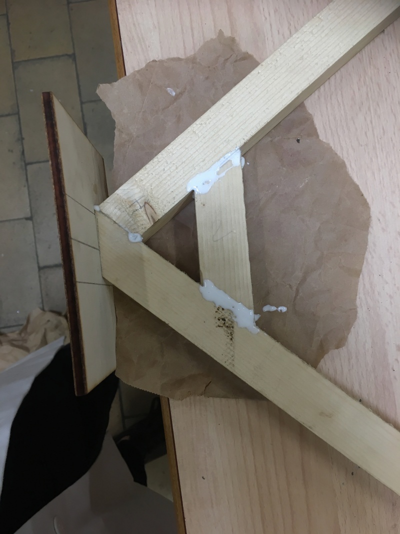
Étape 7 - Solar concentrator 1 - Pipe support 1.3.1 - Step 1
Step 1: Cutting the battens
- Cut the battens into four pieces approximately 65 cm long.
- Cut inclined planes at the end of the 4 pieces so that they can be glued together 2 by 2 (see photo). After gluing, the top should be 80cm above the frame.
- Cut other inclined surfaces on the other side of the 4 pieces so that they can be fixed to the 1.1 frame.
Étape 8 - Solar concentrator 1 - Pipe support 1.3.1 - Step 2
Step 2: Secondary reflector support 1.3.1 and clamps
- Grind the cut surfaces to make the glue more effective.
- Glue the cleats C from the previous step in pairs. Board B must be 80cm above the frame.
- Screw the two boards B to the battens C (see photo) using the clamp support A.
Étape 9 - Solar concentrator 1 - Pipe support 1.3.1 - Step 4
Step 4: Consolidation
- Using the off-cuts of battens, cut pieces and glue them to the supports, taking care to sand them as before, so as to consolidate the structure.
Étape 10 - Solar concentrator 1 - Pipe support 1.3.1 - Step 5
Step 5: Screwing
- All that remains is to screw the two pieces of the pipe support structure 1.3.1 to the frame 1.1 from underneath the structure.
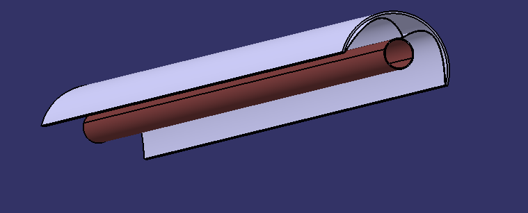
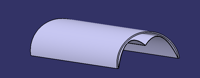
Étape 11 - Solar concentrator 1 - Secondary reflector 1.3 - Presentation
The secondary reflector 1.3 reflects light rays not intercepted by the copper tube 1.3.2 back onto it. It is located above the tube 1.3.2.
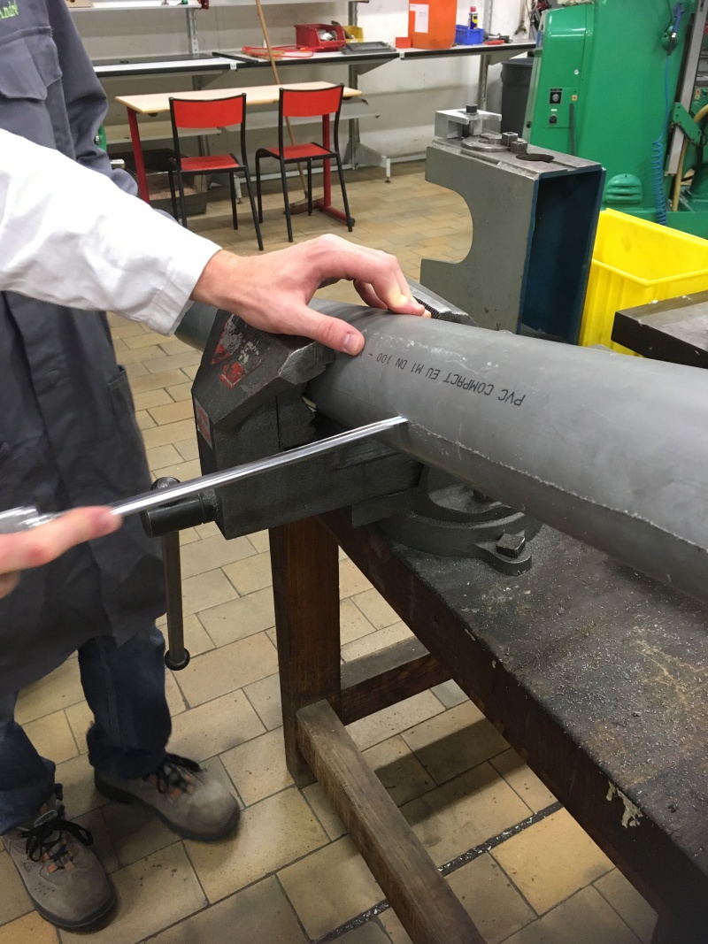
Étape 12 - Solar concentrator 1 - Main reflector 1.3 - Step 1
Step 1: Cutting the PVC pipe
The PVC tube is what supports the secondary reflector 1.3. It holds the soda cans that reflect the light rays.
- Cut the PVC pipe in half lengthways.
- Colour the outside of the PVC pipe black with paint.
Étape 13 - Solar concentrator 1 - Main reflector 1.3 - Step 2
Step 2: Cutting and gluing the cans
As the cans are made of aluminium, the inside of the can proved to be a good alternative for reflecting light rays.
- Cut the cans into rectangles 9cm wide, there are no length constraints for the other sides.
- Fold in half widthways to make two parts 4.5cm wide.
- Glue the cans into the PVC tube (they will have a rounded W shape) using strong glue.
- Note: you can stick self-adhesive mirrors in the cans to improve reflection.
Étape 14 - Watermaker 2 - Presentation
- Name of the different parts of the watermaker 2
- Material: steel
- Copper tubes
- The condensation tank 2.2 is used to store brackish water before the evaporation tank 2.1. In this tank, the steam created by the evaporation tank 2.1 circulates in a coil 2.2.2.1.
- The evaporation vat 2.1, consisting of 2 stages 2.1.2, is used to convert brackish water into steam. The vapour created circulates through a coil 2.2.2.1 in the condensation tank 2.2 in order to cool it and convert it into a liquid state.
- Desalinated water is thus obtained.
Étape 15 - Watermaker 2 - Evaporation tank 2.1 - Step 1
Step 1: Manufacture of the frame 2.1.1
- Cut the metal sheet into 6 rectangles (2 rectangles of 4cm*15cm; 2 of 1m*15cm; 1 of 1m*4cm; 1 of 6cm*1.02m). See photo.
- Fold at right angles over 1 cm as shown in the dotted lines in the photo, then make holes in the folded part to fit the screws.
- Note 1: Be careful to ensure that the walls of tank 2.1 are watertight (soldering is required)!
- Note 2: Be careful to seal between the lid and the folded walls (use a bicycle inner tube, for example, before screwing)!
Étape 16 - Watermaker 2 - Evaporation tank 2.1 - Step 2
Stage 2: Manufacture of stages 2.1.2
- Cut out 2 trays measuring 99.6cm*3.6cm.
- Add material by welding to the side walls of vat 2.1 so that the trays can be placed on them (see photo for the height of the 2 trays and therefore the height of the 2 additions of material).
- Drill 5 cm diameter holes at one end of each tray (so that steam can circulate through all the levels) and place the 2 trays in vat 2.1 with their holes located at opposite ends.
Étape 17 - Watermaker 2 - Evaporation tank 2.1 - Step 3
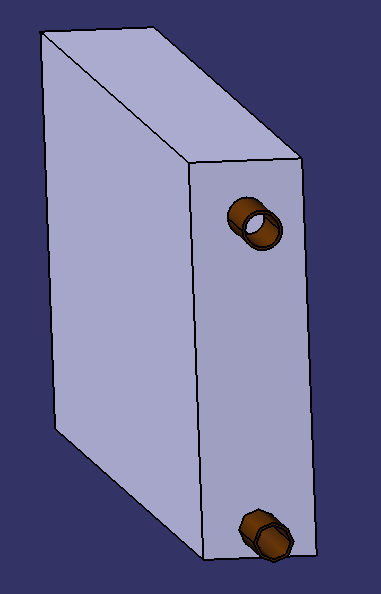
Step 3: Making the 3 holes for the copper pipes inlet to the condensing coil 2.2.2.1 and pipe 2.2.2.3 which passes through the tank 2.1 at the bottom.
- In the 2 side walls furthest from tank 2.1: make a 14 mm diameter hole (see photo for position) in the bottom tier for pipe 2.2.2.3.
- In one of these same side walls, make a 14 mm diameter hole in the top tier (for the 2.2.2.1 pipe used to evacuate the steam).
- Solder to make a seal between the pipes and the tank!
Étape 18 - Watermaker 2 - Evaporation tank 2.2 - Step 1
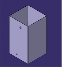
Step 1: Cutting the sheet into 5 sections
- 5-sided cut-out
   * Base side: 200x200mm
   * 4 side panels: 200x355mm
- Fold the side faces on top to create edges for screwing on a lid (using the same system as in the previous step).
- Welding of the base and 4 sides
Étape 19 - Watermaker 2 - Evaporation tank 2.2 - Step 2
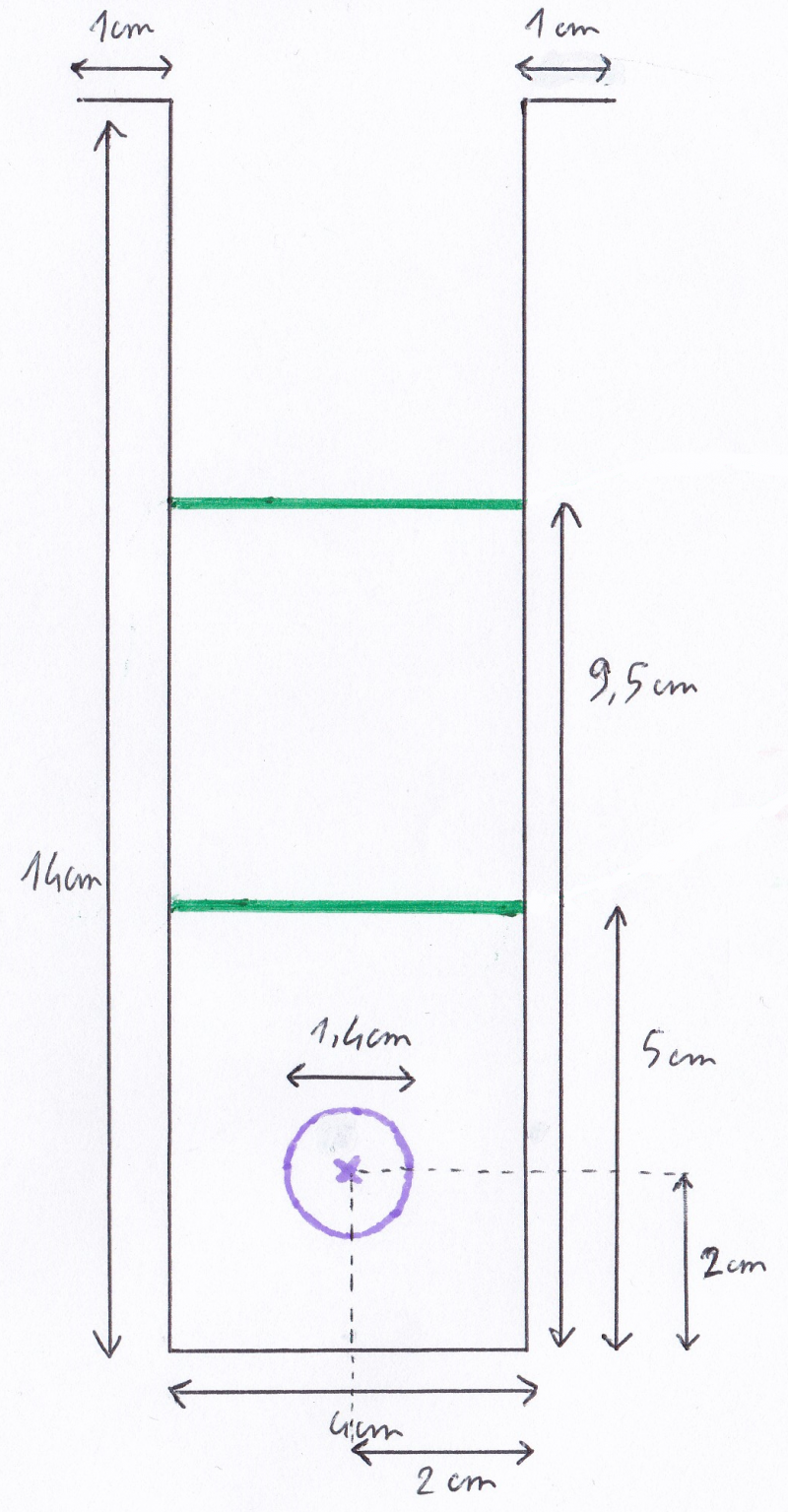
Step 2 : Holes
Four holes to drill:
- A water inlet hole from the storage tank, which accommodates a flow regulator (such as a flush valve for autonomous use, but a simple manual valve may suffice). This hole should be at the top of the tank. The 2.2.2.2 pipe passes through it.
- An outlet hole for brackish water preheated by steam condensation, at the bottom of tank 2.2, towards evaporation tank 2.1. Pipe 2.2.2.3 passes through.
- A steam inlet hole from the evaporation tank 2.1 (condensation coil inlet 2.2.2.1), located below the water level in tank 2.2.
- A drinking water outlet hole (condensing coil outlet 2.2.2.1), lower than the previous hole.
- Note: these holes must be made in relation to the other parts of the prototype (particularly for the condensation coil 2.2.2.1 where it is advisable to manufacture it before drilling the holes: see next step).
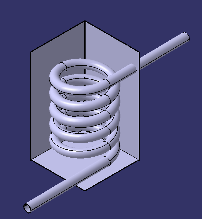
- See image where the brackish water outlet hole is not shown (water inlet: top right and the 2 ends of the condensing coil 2.2.2.1 are top left and bottom right).
Étape 20 - Watermaker 2 - Evaporation tank 2.2 - Step 3
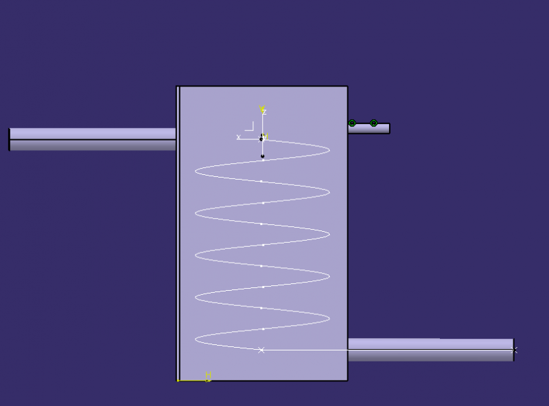
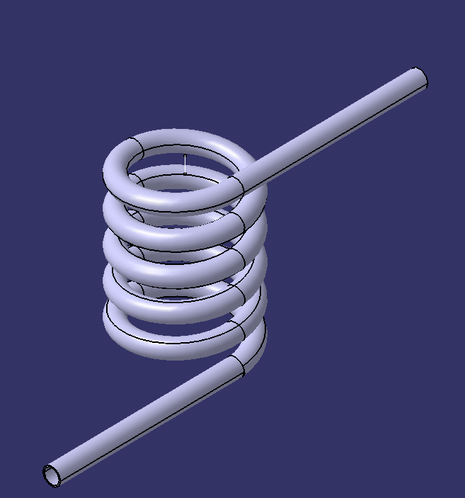
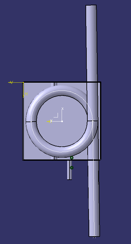
Step 3: Condensing coil 2.2.2.1 (where the steam condenses)
- Surround the copper tube 2.2.2.1 with a rigid spring (to obtain a circular shape).
- If the copper is not annealed, heat it to a red colour and immerse it in cold water immediately.
- Then give it a helical shape by gradually winding it around a cylinder.
- Insert the coil 2.2.2.1 into the tank 2.2 through the 2 holes previously made.
Étape 21 - Watermaker 2 - Evaporation tank 2.2 - Step 4
Step 4: Lid 2.3 of tank 2.2
- Drill at least 8 holes on the edges of the tank 2.2 for the screws that will secure the lid 2.3.
- Cut a 250x250mm square sheet to serve as the lid 2.3 and drill at least 8 holes in it corresponding to the previous ones so that the lid can be screwed on;
- A bicycle inner tube can be inserted between the edges of tank 2.2 and lid 2.3 for a better seal.
Étape 22 - Total circuit 3
Now that the two main parts have been built, all that remains is to close the circuit where the heat transfer fluid will circulate! The heat transfer fluid is vegetable oil, which will be circulated by the 3.2 pump built into the circuit. 3.1 pipes should be well insulated (insulate yourself if necessary) and flexible (so you can move the prototype easily).
Étape 23 - Pump 3.2
When choosing the 3.2 pump, care must be taken to use an oil pump. Such a pump may be a recovery pump and may be found on motorbikes or cars or any other machine whose operation requires an oil pump.
Published





 Français
 English
 Deutsch
 Español
 Italiano
 Português