
| Ligne 3 : | Ligne 3 : | ||
|Main_Picture_annotation={"version":"3.5.0","objects":[{"type":"image","version":"3.5.0","originX":"left","originY":"top","left":-15,"top":1,"width":6000,"height":4000,"fill":"rgb(0,0,0)","stroke":null,"strokeWidth":0,"strokeDashArray":null,"strokeLineCap":"butt","strokeDashOffset":0,"strokeLineJoin":"miter","strokeMiterLimit":4,"scaleX":0.11,"scaleY":0.11,"angle":0,"flipX":false,"flipY":false,"opacity":1,"shadow":null,"visible":true,"clipTo":null,"backgroundColor":"","fillRule":"nonzero","paintFirst":"fill","globalCompositeOperation":"source-over","transformMatrix":null,"skewX":0,"skewY":0,"crossOrigin":"","cropX":0,"cropY":0,"src":"https://wiki.lowtechlab.org/images/1/1e/Remorque_g_n_rateur_solaire_DSC_0363.JPG","filters":[]}],"height":449.78662873399713,"width":600} | |Main_Picture_annotation={"version":"3.5.0","objects":[{"type":"image","version":"3.5.0","originX":"left","originY":"top","left":-15,"top":1,"width":6000,"height":4000,"fill":"rgb(0,0,0)","stroke":null,"strokeWidth":0,"strokeDashArray":null,"strokeLineCap":"butt","strokeDashOffset":0,"strokeLineJoin":"miter","strokeMiterLimit":4,"scaleX":0.11,"scaleY":0.11,"angle":0,"flipX":false,"flipY":false,"opacity":1,"shadow":null,"visible":true,"clipTo":null,"backgroundColor":"","fillRule":"nonzero","paintFirst":"fill","globalCompositeOperation":"source-over","transformMatrix":null,"skewX":0,"skewY":0,"crossOrigin":"","cropX":0,"cropY":0,"src":"https://wiki.lowtechlab.org/images/1/1e/Remorque_g_n_rateur_solaire_DSC_0363.JPG","filters":[]}],"height":449.78662873399713,"width":600} | ||
|Licences=Attribution (CC BY) | |Licences=Attribution (CC BY) | ||
| − | |Description=This tutorial presents the sizing and construction of an electrical system for a solar generator (1 kWp or ‘kilowatt peak’) which can be moved by bicycle. This structure was designed to fit on the CHARRETTE, an assisted trailer designed by the Véloma association whose plans are freely available. | + | |Description=This tutorial presents the sizing and construction of an electrical system for a solar generator (1 kWp or ‘kilowatt peak’) which can be moved by bicycle. This structure was designed to fit on the CHARRETTE, an assisted trailer designed by the Véloma association, whose plans are freely available. |
|Area=Energy | |Area=Energy | ||
|Type=Tutorial | |Type=Tutorial | ||
Version du 26 mai 2023 à 18:32
Dernière modification le 26/05/2023
Difficulté
Moyen
Durée
3 jour(s)
Coût
3000 EUR (€)
Description
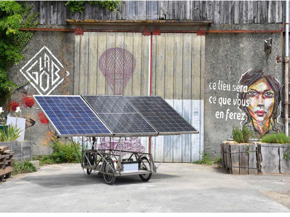
This tutorial presents the sizing and construction of an electrical system for a solar generator (1 kWp or ‘kilowatt peak’) which can be moved by bicycle. This structure was designed to fit on the CHARRETTE, an assisted trailer designed by the Véloma association, whose plans are freely available.
Sommaire
Sommaire
- 1 Description
- 2 Sommaire
- 3 Introduction
- 4 Étape 1 - Evaluate your needs and identify the most suitable energy sources.
- 5 Étape 2 - Calculate your daily electrical needs
- 6 Étape 3 - Parameters of principal elements
- 7 Étape 4 - Sizing of principal elements
- 8 Étape 5 - Sizing of electrical protections
- 9 Étape 6 - Wiring sizing
- 10 Notes et références
- 11 Commentaires
Introduction
This trailer is a functional demonstration designed as a part of the Scholar Grid project.
Supported and piloted by the Fondation Schneider Electric in partnership with these associations Low-tech Lab,Énergies sans Frontières and Atelier 21, this project intends to investigate innovative solutions to provide affordable and clean electric energy to training centers that train future electricians. The energy systems created by the technical experts and the teachers of the training centers, will be implemented by students and serve as a pedagogical base.
The fields of investigation of this project were the following:
- The recovery and repair of damaged photovoltaic panels.
- The recovery and regeneration of used lead batteries.
- Direct current microgrids.
To test these techniques in real conditions, Low-tech Lab constructed a mobile generator trailer. With the power of 1kW, it combines the repaired second hand solar panels and the regenerated lead batteries. This was designed on the basis of concrete needs: to provide electricity for the Festival Low-tech organized in Concarneau in July of 2022.
Beginning with this concrete case, "the tutorial details the general steps of sizing a photovoltaic installation in self-consumption". The context, the preliminary evaluation of needs and the choice of adapted energy sources are explained in detail in the document "An energy-autonomous Festival?’ In the ‘Files’ section".


Matériaux
| Quantity | Designation | New Material Price | Project Material Price (donation, second-hand, reclaimed) |
|---|---|---|---|
| 3 | Peimar 330W Solar Pannel | 500 | 105 |
| 1 | Victor Energy Phoenix 24V/1200VA Inverter | 503 | 200 |
| 1 | Schneider Electric Connext 60A/150V MPPT charge controller | 650 | 0 |
| 12 | Hawker 4PzS240 traction battery - 2V 240Ah | 1980 | 650 |
| 1 | Victron Energy BMV700 battery controller + crimped cable + wall bracket + VE Direct Bluetooth Smart Dongle | 250 | 250 |
| 1 | Fuse MEGA-Fuse 125A / 32V (x5) + Fuse holder MEGA Victron Energy | 33 | 33 |
| 1 | Schneider Electric C120N 125A Circuit Breaker | 320 | 0 |
| 2 | Schneider Electric iC60N 63A Circuit Breaker | 25 | 0 |
| 1 | Schneider Electric Resi9 10A Circuit Breaker | 15 | 0 |
| 1 | Schneider Electric 30mA/40A differential Circuit Breaker | 90 | 0 |
| 16m | 1x4mm² red/black solar cable with MC4 connector | 24 | 0 |
| 1 | Male MC4 Connector | 4 | 0 |
| 1 | Female MC4 Connector | 4 | 0 |
| 6m | Red / blue / green-yellow cable 1x16mm² | 16 | 16 |
| 6 | Tubular battery terminal 16mm²-12 | 4 | 4 |
| 2 | Tubular battery terminal 35mm² - 10 | 2,6 | 2,6 |
| 6 | Gray PG16 cable gland + Washer | 11,5 | 11,5 |
| 6 | Gray PG11 cable gland + Washer | 9,5 | 9,5 |
| 1 | Bloc multiprise extérieur IP44 | 14 | 14 |
| TOTAL | 4442 € (~4,764.22 $USD) | 1282 € (~1,375.00 $USD) |
Outils
Étape 1 - Evaluate your needs and identify the most suitable energy sources.
The cheapest and cleanest energy is that which we do not produce/consume !
In line with this principle, this approachnégaWatt proposes to rethink our vision of energy by applying a three step approach: Sobriety, Efficiency, then renewable energy. Before sizing a photovoltaic electrical installation, it is necessary to consider several questions:
- What are my needs?
- Which are essential and incompressible?
- Is electricity the most efficient way to meet all these needs?
Detail on these questions applied to the case of our Festival is available in the "Files" tab located above.
To materialize the electricity consumption of everyday equipment and possibly be able to eventually prioritize, the open-source game REVOLT translates these consumptions in pedaling time.

Étape 2 - Calculate your daily electrical needs
Me: This step is the most important of an autonomous photovoltaic sizing. It will have a big influence on the price, autonomy, and the durability of the installation.
This step will permit you to see where your large electrical consumption items are located and to make choices accordingly. (Ex: An electric oven demands 5000W of power. Is electrical energy the most pertinent to respond to this need?)
Several softwares can help you in sizing a solar installation. We have used the free software CalcPvAutonome developed by David Mercereau. A interface dédiée lets you calculate your daily electrical needs. We came up with what we call an Energy audit (simplified).
The principle is simple:
- We listed all the equipment being used
- We indicate their power (In Watts, W)
- We indicate the duration of their daily use (in hour/day, h/d)
- We determine if certain equipment is capable of functioning simultaneously
- The tool gives us a daily energy consumption (in watt per hour by day, W.h/d)
{{Warning l Certain devices do not consume the same quantity of energy all the time. For example, even if a refrigerator is permanently plugged in, it does not consume energy until the interior temperature passes a certain level.
There is also the option to enter the energy consumption manually. For that, you have to measure it! Connect a Wattmeter-Consometer to the equipment for 1 to 7 days to have the actual daily consumption (see image).}}
In the case of our Festival, we have thus evaluated our electrical needs (see image) :
- Daily electrical needs: 4080Wh/d
- Maximum electrical power need: 177W
We have deliberately chosen to not fuel the power hungry devices in energy by electricity !
>The kitchen (for 100 people) was made using a wood-burning stove.
> To serve fresh beverages, we have agreed to a partnership with the Concarneau auction that permanently produces ice and stored it in an unplugged freezer (vs.4800Wh/d). In the same way, the beer taps are frozen directly with the ice and stay disconnected (vs 5600Wh/d).

Étape 3 - Parameters of principal elements
Once the energy needs are entered in CalcPVAutonome, several important parameters must be entered for the sizing.
Parameters of Solar Panels (SP):
- Inclination of the PV: The position of the sun in the sky varies in accordance with the seasons (high in the summer, low in the winter). It is therefore recommended to adapt the positions of the PV to be perpendicular to the rays. In France, we recommend 30° of inclination in the summer and 60° in the winter.
- If the PV are attached to the roof, we recommend the position during the worst period of production, winter, so 60°.
- For the trailer, we have chosen 30° because its use is more likely during the summer season. But the incline angle can always be changed on the trailer.
- Orientation of the PV: One should determine the angle of the SP with the sun. If they face south, they should be at 0°. If not, see image.
- Desired autonomy: Will I use my PV all year or punctually? For the trailer, the use will be seasonal, from June to September globally.
- Technology of Solar Panels: Even if the differences are minimal between poly and monocristalin (see comparatif), we have chosen monocristallin because they are the most recent.
Battery Bank Settings
- Number of days of desired autonomy: This represents the number of consecutive days without sun that you can get by. This parameter has a big influence on the capacity of the battery bank and therefore on the installation cost. For the trailer, we have chosen the average duration of a festival over one day, which is 8 hours. This lets us have a battery pack that remains mobile.
- Battery Technology: To choose refer to the tutorial "Operation, maintenance and regeneration of lead acid batteries". Otherwise, leave "auto." by default.
Wiring
- If you have an idea about the location of the SP related to local technique, specify these distances. If in doubt, overestimate a little.
Geographic Location:
- Specify your location. The average radiation data per month is calculated via the database PVGIS.


Étape 4 - Sizing of principal elements
Once the parameters are entered, we begin the calculation!
CalcPVAutonome Proposes an estimate of necessary material in accordance with these parameters. This is given for information only and must be analyzed. In our case, we have readjusted accordingly with the material already available to us that we used.
Photovoltaic panels :
To satisfy our daily needs of 4080Wh/d, a minimal SP power of 937W is required (detailed calculations done by the software). The software tells us that 5 monocrystalline panels of 190W would work.
But 5 panels were too cumbersome for our trailer + we already had 1 solar panel of 330W. We have chosen 3 panels of 330W for a total power of 990W.
Batteries:
Generally, the voltage of a battery pack is determined in accordance with the power of the SP:
- <500W: 12V
- 500 -1500W: 24V
- >1500W: 48V
In our case, we have 990W of SP, therefore the final voltage of our battery pack will be 24V.
To allow an autonomy of 8 hours (~0.3d), the software calculates that the nominal capacity of batteries of 170Ah en C10. (See detailed calculation in image)
However, to ensure the longevity of the battery packs, their charging current must not exceed 20% of their normal capacity. (See Operation, maintenance and regeneration of lead acid batteries)
That is: 170 x 20% = 34A.
Or, with 990W of SP the charging current is 990 / 24 = 41,25A.
You can choose to restrict the production of SP thanks to the charge regulator, but generally we advise you to increase the capacity of the battery packs in consequence. So here, 41,25 x 100 / 20 = 206Ah.
Having found a good opportunity, we have finally opted for the purchase of a set of battery packs Operation, maintenance and regeneration of lead acid batteries l regenerated traction batteries of 240Ah. It consists of 12 240Ah-2V batteries assembled in a series to have a voltage of 24V. This will raise our autonomy to 10 hours.
Charge Controller :
The characteristics of the charge regulator are determined in accordance with the characteristics of the maximum current leaving the SP. We therefore need the characteristics of SP given by their technical file or on the back of the panels. It is necessary to know the " Open Circuit Voltage " (Voc) and the "Intensity of Short-Circuit Current " (Isc) of SP.
In our case, for each panel: Voc= 40,49V and Isc= 10,25A
When adding the panels in series: Voc_tot= 121,5V et Isc_tot= 10,25A
In taking safety margins of 20%, a 150V 20A MPPT regulator might have been suitable.
Having had the opportunity to recover a "'Conext MPPT 150V/60A regulator"', we opted for this model.
Converter - Inverter :
The choice of converter is decided in accordance with the power that the installation must deliver (in AC) and in accordance with the voltage of the battery pack
We wanted to be able to occasionally power devices up to 1000W.
We have opted for a "'Victron 24V/1200VA"' converter that increases the maximum output power of 1200W with possible peaks up to 2400W.
Battery Monitor
To know the charging state of our batteries and to prolong their lifespan, we have chosen to use a battery monitor (strongly recommended).

Étape 5 - Sizing of electrical protections
What Electrical Protection ?
- Isolating and breaking devices ("'circuit breaker and/or switch - disconnector"') must be installed in different places to install and maintain the system safely :
- Between the SP and the charge controller
- Between the charge controller and batteries
- Between the batteries and the inverter
- Between the batteries and the DC loads
The devices are placed on the 2 polarities (+ and -)
- Overcurrent protective devices ("'fuses or circuit breakers"') must be installed to protect the equipment from high current conditions:
- At the SP output, on the two polarities (+ and -), against the risks of overcurrent under the forme of courant retour. Not necessary, if you have only one channel of SP in series.
- At the battery output, on the +, against the high discharge currents.
Sizing of electrical protections :
Between the SP and the charge controller:
- Fuses at the output of each SP string in series (obligatory only if you have more than one SP string/channel, which is not the case on the trailer):
- 1,5 Isc_tot< Ifuse < 2,4 Isc_tot
- 1,1Voc_tot < Vfuse
- Circuit breaker or switch-disconnector between the SP and the charge controller
- I> 1,25 Isc
- V >1,15 Voc_tot
So for the trailer, we have chosen a circuit breaker that meets these conditions : - I > 12,8A
- V > 140V
Between the charge regulator, the inverter and the batteries:
- Fuses, to be placed on the positive cable, at the battery input:
- Ifuse > Iop
Iop Being the current in operation. It varies if you are in battery charging or discharging mode :
- In charging mode, it is equivalent to maximum current provided by the Charge Regulator. That being,Iop= 60A in our case.
- In discharging mode, it is equivalent to the maximum current pulled by the inverter. Let, Iop= Pmax_inv/ (inverter output*Vbat )= 2400W / (0,97*24V) = 104A
"'We chose the maximum value so"'Ifuse>104 A'. We have chosen a MEGA 125A 32V fuse from Victron Energy.
- Circuit breaker or switch-disconnector between the SP and the charge controller
- I> 1,25 Isc
- V >1,15 Voc_tot
So for the trailer, we have chosen a circuit breaker that meets these conditions : - I > 12,8A
- V > 140V

Étape 6 - Wiring sizing
To avoid the losses due to overheating, or even fire risks, it is important to size all the installation cables correctly. That is to say, calculate the minimum section (in mm²) of the cable
The formula is the following :
S > ρ*2*L*I / ε*U
For this you need to know:
- The maximum current that will cross the cable on the studied segment ( l, in Amps)
- The voltage of on the studied segment (U, in Volts)
- The length of the cable on the studied section (L, in meters)
- The material and also its resistivity (ρ, en Ohm.mm²/m). For the copper, we generally take ρ=0,023 Ω.mm²/m
- Maximum allowable voltage drop ε. we often choose 1% or ε=0,01
- From solar panels to charge controller
- From regulator to batteries
- From regulator to inverter
| Between the SP and the charge regulator | 'Between the charge regulator and the batteries | Between the batteries"' and the inverter |
|---|---|---|
| S > 0,023*2*4* 10,25 / 121,5*0,01 | S > 0,023*2*1* 1000 / 24*24*0,01 | S > 0,023*2*0,5* 2400 / 24*24*0,01 |
| S> 1,55mm² | S>7,9mm² | S>9,5mm² |
From these calculated sections, it is then necessary to choose the upper commercial section:
| Between the SP and the charge regulator | Between the charge regulator and the batteries | Between the batteries and the inverter |
|---|---|---|
| S = 2,5mm² | S= 10mm² | S=10 ou 16 mm² |
We can verify the maximum allowable intensity values corresponding to these sections in the counting frame (see image).

Notes et références
Document by Guénolé Conrad within the framework of the Scholar Grid project. A project initiative of the Schneider Electric Foundation with the technical support of Energie Sans Frontières, Atelier 21 and the Low-tech Lab
- To go over the basic details, operation and sizing of an autonomous solar installation, the very good e-learning of l'INES, the National Institute of Solar Energy (in English) or the site GuidEnR Photovoltaïque (in French)
- Notions de sécurité électrique and effects on the human body.
- Pre-sizing tool for photovoltaic solar installation in self consumption designed by l'INES: AutoCalSol
- In France, to train in a more professional way, l'INES offers formations sur l'énergie solaire
- The construction tutorial for the Support structure for solar panels.
English Translation by Suzanne Kane
Published
 Français
 English
 Deutsch
 Español
 Italiano
 Português