Description
Capturing solar energy for domestic hot water or high-efficiency heating
Sommaire
Sommaire
- 1 Description
- 2 Sommaire
- 3 Introduction
- 4 Video d'introduction
- 5 Étape 1 - Preface
- 6 Étape 2 - Grid recovery
- 7 Étape 3 - Door recovery
- 8 Étape 4 - Panel sizing
- 9 Étape 5 - Making the frame
- 10 Étape 6 - Frame painting
- 11 Étape 7 - Assembling the grid and copper pipes (feeders)
- 12 Étape 8 - Installing the grids in the frame
- 13 Étape 9 - Panel closure
- 14 Étape 10 - Additional panels
- 15 Étape 11 - Installation
- 16 Étape 12 - Solar heating
- 17 Étape 13 - Contenu pédagogique à télécharger
- 18 Notes et références
- 19 Commentaires
Introduction
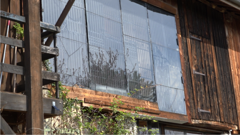
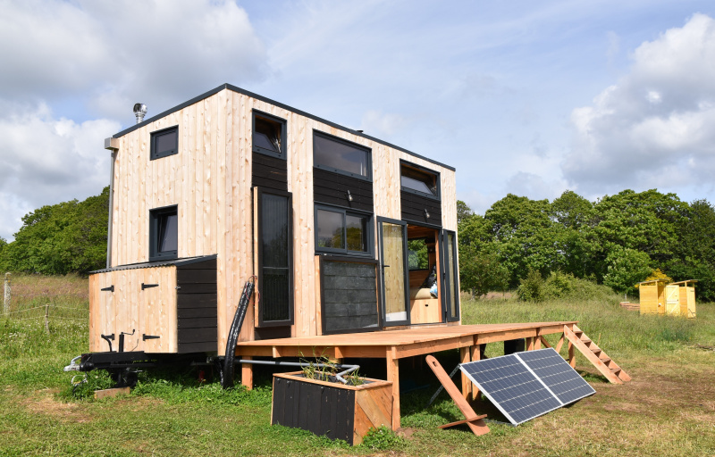
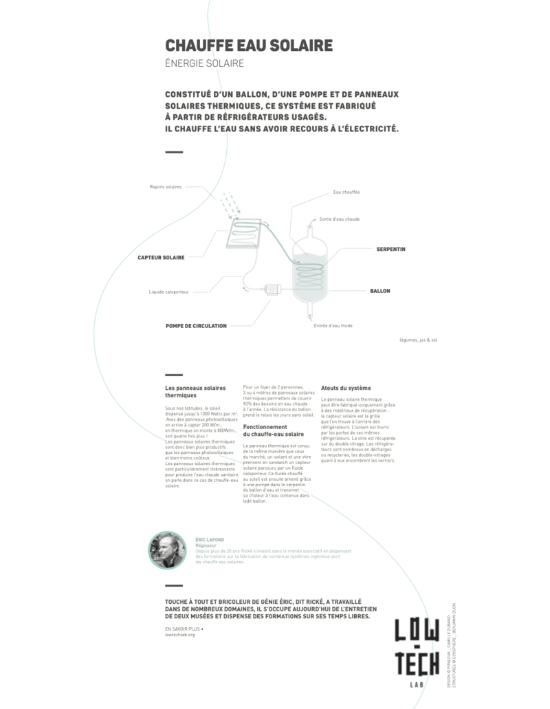
Solar panels are very efficient at taking advantage of solar radiation. In our latitudes the sun generates up to 1000 Watts per m². With photovoltaic panels we can capture 200 W / m², with thermal energy it rises to 800W / m², four times more! Solar panels are much more profitable than photovoltaic panels and much less expensive. The "home made" solution Eric Lafond offers us easily reaches 500W / m² for a cost of 15 € per m².
This [1] shows the solar power you can expect to receive, depending on your geographical position and the season.
Solar thermal panels are particularly useful for domestic hot water production. In this case they are called solar water heaters.
3 - 4m² (32 - 43 sq feet) of solar thermal panels will cover 90% of the hot water needs for a two person household throughout the year. The hot water tank will take over during cloudy days. If there are more inhabitants, and therefore more water being consumed, you need to increase the size of the solar panels. For example, 6m² (64.5 sq feet) for 6 people.
Eric's complete system - which includes home-made panels, supply pipes, coolant, solar balloon, circulator, and a regulator - will be profitable in two to three years. The panels installed at his house are in their eighteenth year.
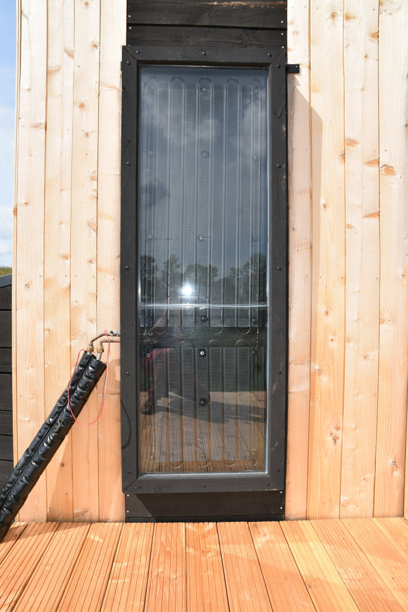
These thermal panels are designed in the same way as those on the market: a solar collector containing a heat transfer fluid is sandwiched between an insulator and a sheet of glass. In this case, we will use the grill you find at the back of a fridge for the solar collector.. And we will use the door of the fridge as the insulator. The glass is from old double glazed windows. You will find many fridges in landfills or recycling areas, and double-glazing windows at many glaziers.
A big thank to Riké, who shared his know-how with us, from his 20 years of experience in the world of energy, and to the members of the Grand Moulin collective who welcomed us to the training they organized, particularly to Karine, Sylvain and Pascal. Thanks also to Jean-Loup for the explanation of glass cutting and soldering, and to all the other volunteers of the participative building site for their help.
Retrouvez dans ce rapport une analyse à l'usage de ce chauffe-eau solaire, ainsi que des 11 autres low-techs expérimentées lors du projet En Quête d'un Habitat Durable.Youtube
Matériaux
- fridge doors of similar size (support)
- grilles on the back of fridge of similar size (sensor)
- rot-resistant wooden battens (douglas, larch ...)
- 16mm-diameter copper tubes (plumbing)
- double-glazed window panel
- wood screw or self-drilling screw
- washers
- polyurethane sealant
- corks
- brass solder rods and paint stripper (?? - should this be flux?)
Outils
- cutter and blades
- pipe cutter
- screwdriver and bits
- hacksaw and/or grinder
- blowtorch
- handsaw and/or circular saw
- sandpaper
- solid iron tube (diameter 12mm)
- protective equipment (goggles, gloves, brazing protection glasses)
Étape 1 - Preface
Orientation panneaux
The thermal solar panels that we are building will have to be installed facing directly south, ideally forming an angle of 60° with the horizon, (or vertically on the outside wall, if the former is not possible). Rooftop usage of these panels is much less efficient in the winter and causes overheating in the summer (more details in the installation phase).
Inertie
To maximize the effectiveness of the thermic solar energy, it is necessary to minimize the inertia in the light uptake and to maximize it in the storage or the diffusion. The panels work as soon as there is a sunbeam thanks to their low inertia. The heat is retained for a long time with its great volume and its good insulation.
The pipes of the refrigerator grill have a small diameter (4mm), so there is a low volume of heat transfer fluid to heat in the panel. This low inertia quickly increases the temperature as soon as the sun appers from behind the clouds and then heats the hot water balloon. The greater the diameter of the pipes, the more time it needs to heat the larger volume of fluid. and the less efficient the system becomes.
To ensure the temperature of the panels increases quickly, the space between the insulation and the glass need to be as small as possible. So the panel has to be as thin as possible, whilst ensuring that the grid doesn't touch either the insulator nor the glass. Otherwise those elements will conduct heat away from the panels.
Température
The temperatures can exceed 150°C (302°F) inside the panel, so it is essential to use materials resistant to heat and to UV radiations. Do not use sticks or paints with solvents which are not resistant to UV radiations. Here, we use PU putty and acrylic paint. For a good longevity, also make sure to use rot-proof local wood.
On winter nights, it can get very cold inside the panel. The different materials, insulation, metal, wood and glass will expand differently between winter night and summer sun. The joints that unite them must be thick to absorb the deformation, if they are not thick enough they will tear off.
Grille
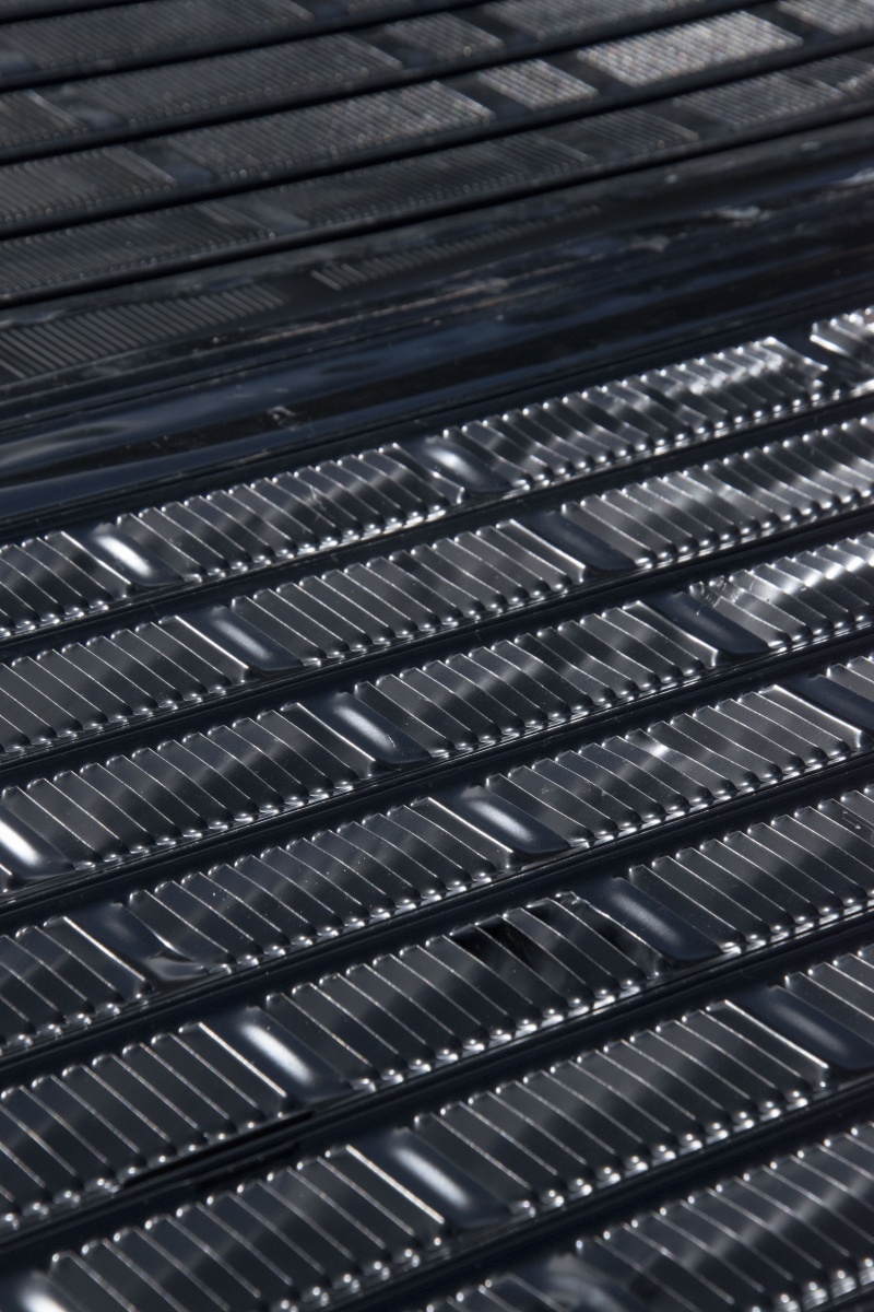
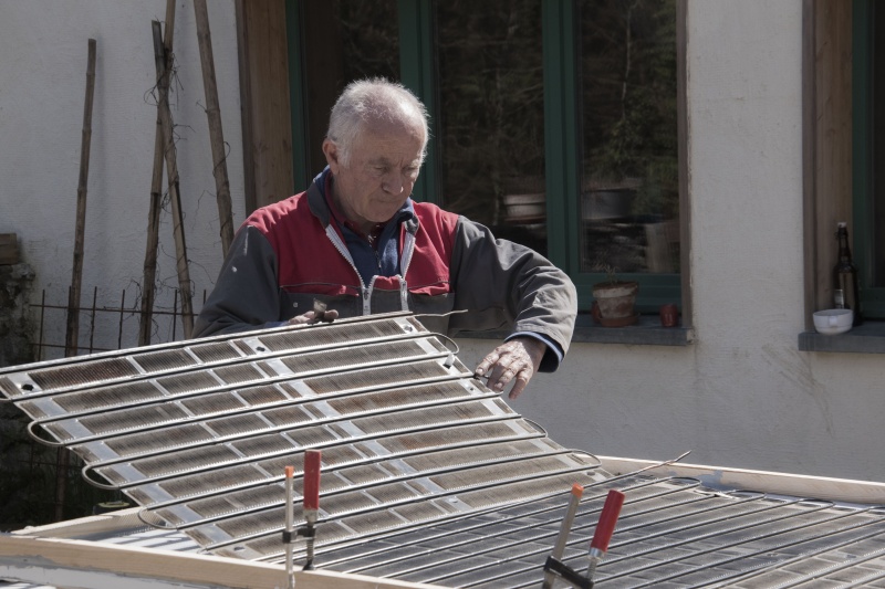
The specific feature and ingenuity of these solar thermic panels is the use of refrigerator coils. But beware, not all coils are good and they must be used in the right direction! The coils must be provided with cooling fins and painted black (see photo). They must not be in galvanized steel, as the paint will not adhere. Similarly, some refrigerators are equipped with pipes connected by wire, but the surface of these coils is insufficient for this use.
The right grilles have a direction of assembly, the fins, comparable to louvers, must capture the sun. In a sense the sun will pass through, it's bad, in the other direction it will capture the rays, it's the good sense! They must be perpendicular to the sun's rays.
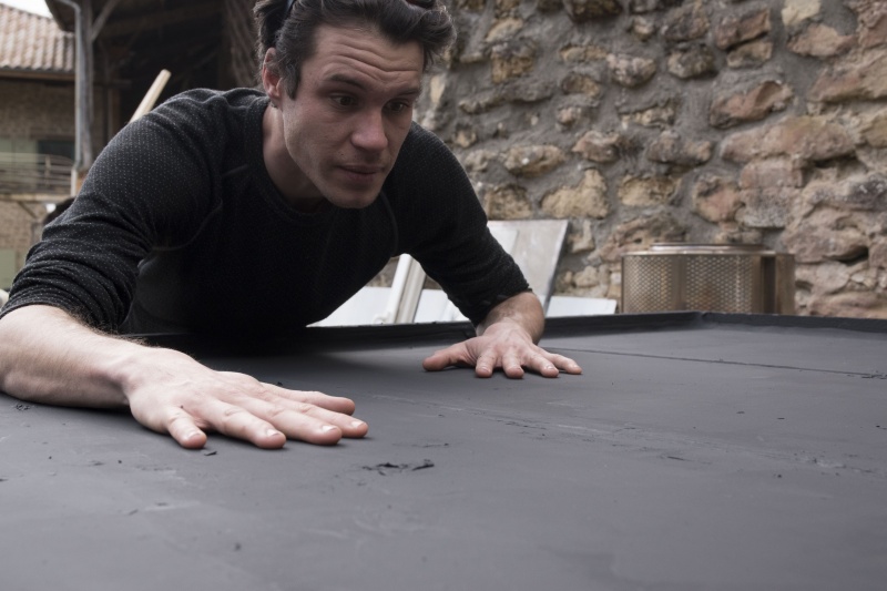
Tip: take the grid and lift it between the sun and yourself, in one sense the rays will pass and not in the other.
Gaz frigorifique
Refrigerator coils are covered by a refrigerant, harmful to the environment, the greenhouse effect and the ozone layer. In France the refrigerating gases must be recovered. However, there are exemptions for equipment containing less than 3 kg of fluid until 2025. The domestic installations (refrigerator and air conditioner) are degassed before continuing their upgrading process. We can open the circuit without too much conscience.
Sécurité
Be careful, you will do something that may involve risks.
The information and advice given in this tutorial come from joint workshops and are neither perfect nor exhaustive. If you don't have certain tools or if you don't feel competent, don't hesitate to ask around for help. Remember to wear your safety equipment, to work in ventilated areas and do not put yourself in danger. Be careful, calm, and of course critical of any false good ideas you may have ("that's how it will go...").
Enjoy!
Étape 2 - Grid recovery
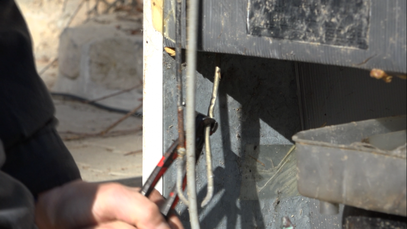
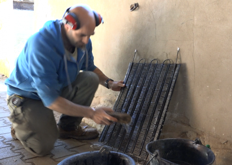
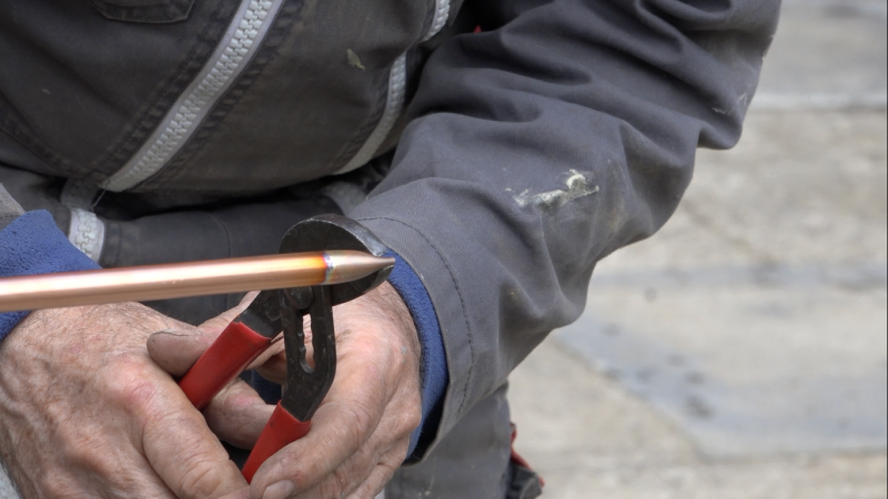
Refrigerators are numerous in waste collection centres, it is necessary to identify those which have the adequate grids (see Preface - Grid) and of the largest possible dimension. Pinching the pipes at the outlet of the compressor will limit the exhaust of refrigerant gases. Cut the pipes as close as possible to the compressor to ensure maximum length with the grid. Unscrew the grid. Wash the grid with soapy water. Blow a blower into the pipes to remove impurities. Seal the pipes with tape to prevent impurities from getting into them, as they may have a small diameter and become obstructed.
Étape 3 - Door recovery
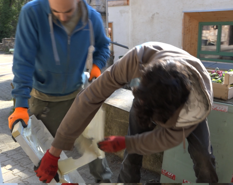
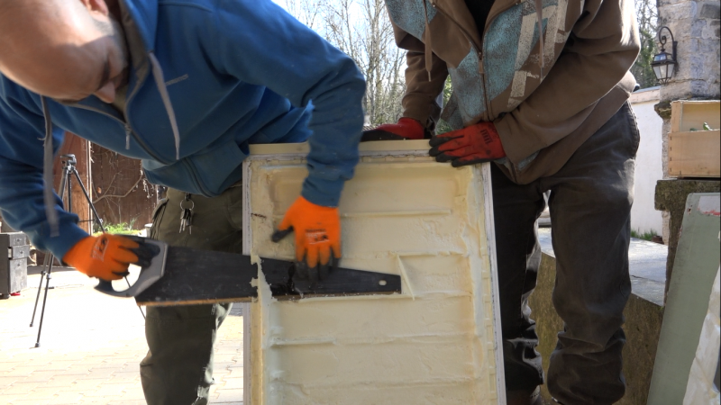
Refrigerator doors are filled with insulating foam. By recovering them and assembling them they form the back of the panel. They must be flat (and not curved), it does not matter if there is a chamfer on the edges, it will be filled with mastic.
- disassemble the refrigerator door.
- Remove all the elements except the insulation and the door sheet: seal, laminations, bolts, handles, screws, stickers... If the inside is not flat, remove it too.
- If the foam insulation is deformed, saw off the protruding parts to make the face as flat as possible. You don't need to have a beautiful surface either, it's the back of the panel.
Étape 4 - Panel sizing
Ideally, the panels should be between 1.5 and 2m², if they are larger they will be heavy and therefore more complex to install. The glass may break if the panels deform. If they are smaller it will be necessary to increase the number of panels, therefore more work to do.
Grilles of similar size, slightly smaller than the doors, should be assembled. For a panel of about 2m² you generally need 3 to 4 grilles for 2 or 3 doors. In our case we have 3 grids and 3 doors.
- Assemble at least 2-3 doors of similar sizes.
- Collect at least 3 grids of similar sizes that fit on the 3 doors.
Étape 5 - Making the frame
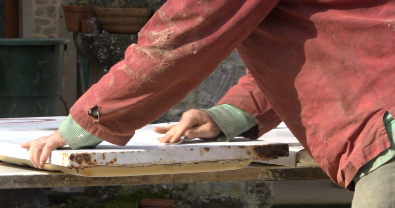
The refrigerator doors form the structure of the panel and are its insulator. They will be glued side by side, in the height. The difference in thickness of the doors does not matter, they are aligned on the front face, on the interior side of the panel.
- Découper les portes afin qu’elles soient toute de la même longueur.
- Poncer les portes
- Disposer les portes sur deux chevrons, longueur contre longueur, côté tôle vers le bas.
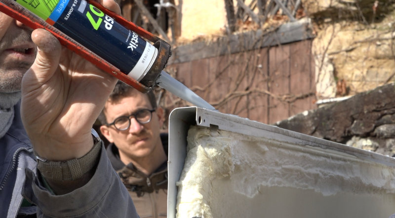
- Faire un joint sur la longueur des portes puis les coller.
- Découper 4 liteaux pour former un cadre sur le panneau.
- Poncer les liteaux
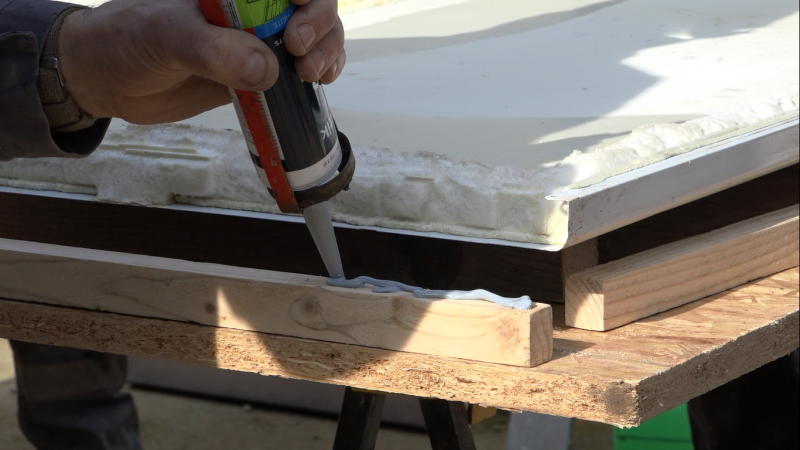
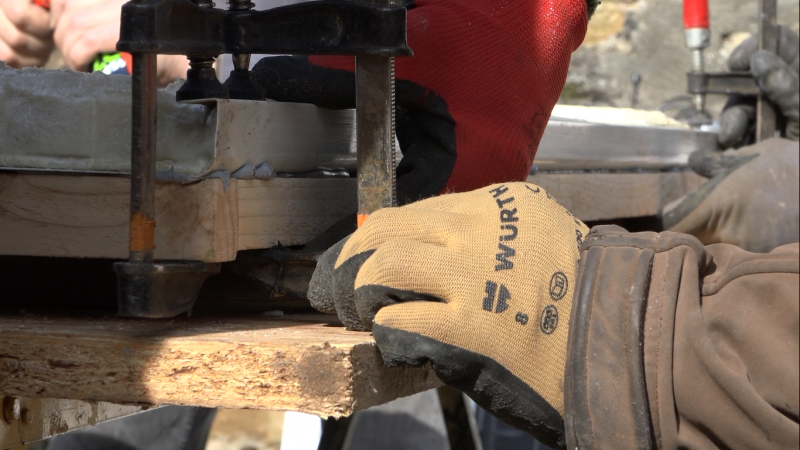
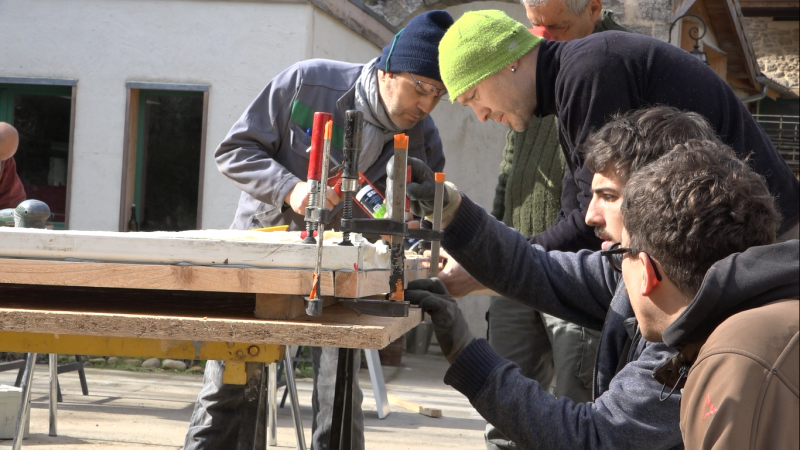
- Mettre du mastic sur la largeur de chacun des liteaux et les coller par-dessous le cadre, contre la tôle, à l'aide de serre-joints. Ne pas trop serrer pour avoir une bonne épaisseur de mastic (>1mm).
- Laisser sécher.
- Retourner le cadre sur les chevrons et faire un joint de mastic à l’intérieur et à l’extérieur du cadre ainsi qu’entre les portes.
- Lisser les joints avec un doigt. Pour bien lisser sans effectuer de « pâtés » et se mettre du mastic plein les doigts, tremper son doigt dans de l’eau savonneuse régulièrement.
- Laisser sécher
Étape 6 - Frame painting
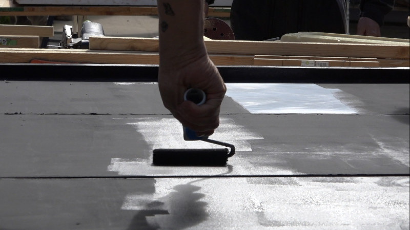
- Paint the frame, battens and door edges with mat black acrylic paint.
- Let dry
Étape 7 - Assembling the grid and copper pipes (feeders)
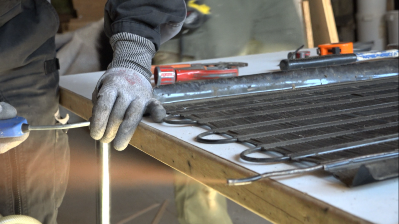
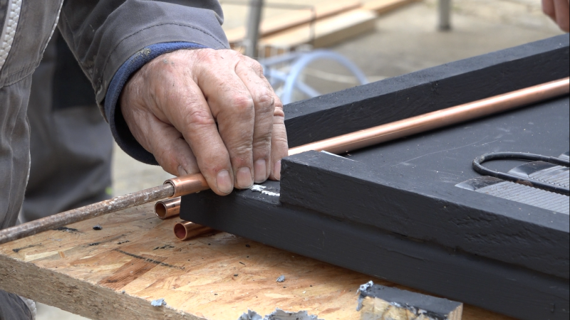
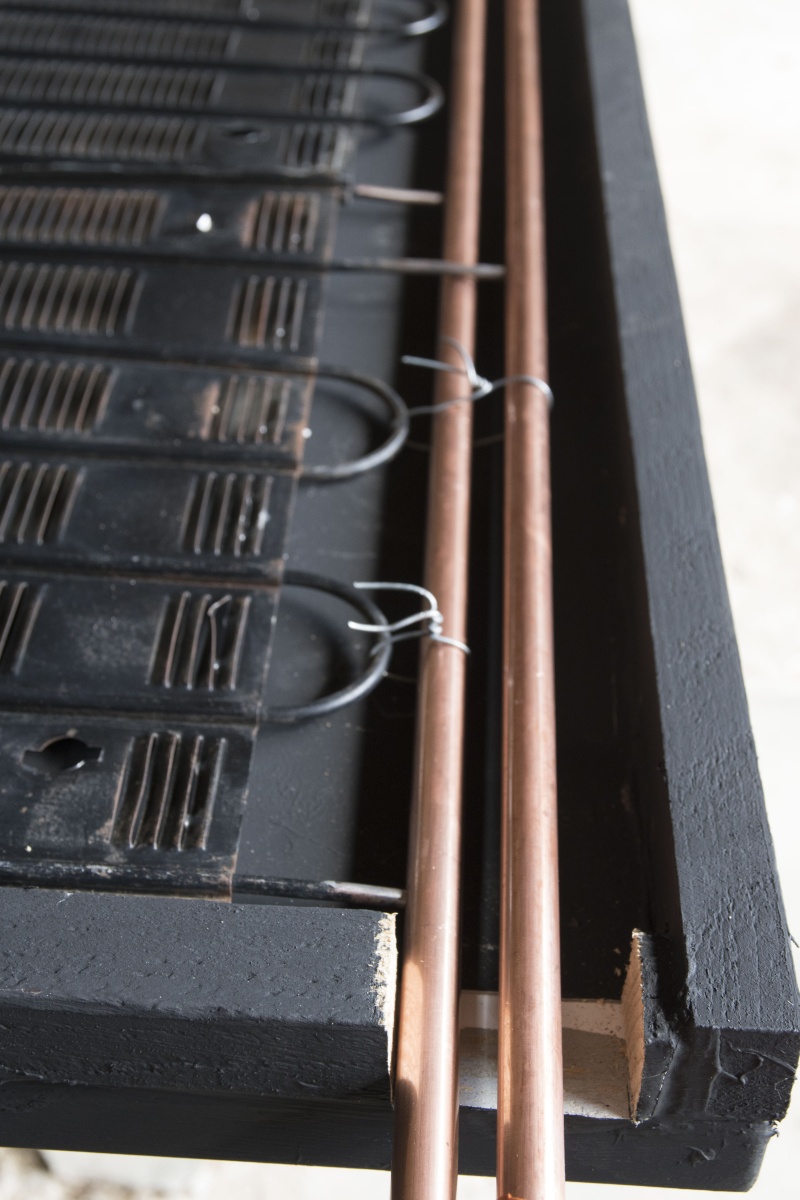
This step consists of connecting the solar collectors (refrigerator grid) to the heat transfer fluid circuit via two feeders (copper tubes). The feeders must have a diameter equal to the sum of the diameters of the pipes they feed, in addition, in our case, 3 pipes of 3mm inside diameter, it is necessary a feeder of at least 9mm inside diameter.
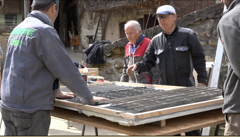
- Position the grids on the frame, in the following direction, the blades in opposition to the sun's rays once the frame is vertical. If necessary, re-cut the grids to the correct size.
- Each grid will be connected to two feeders, one with a "cold" water inlet and the other with a "hot" water outlet.
- For each grid, cut the pipe with a pipe cutter about 10 cm from the grid and the other about 15 cm from the grid. It must be possible to fit each tube in a different feeder in the same plane.
- Deburr the cuts
- Carefully clean the tubes cut to a few centimetres with sandpaper. There must be no paint left to solder successfully.
- Cut a passage in the frame to get the feeders out.
- Cut 2 copper pipes, the feeders, so that they protrude about 15 cm from the panel
- Position the two feeders. One will receive the "short" hot water pipes, the other the long cold water pipes.
- Crush the ends of the two feeders on the blind side of the frame, the one by which the feeders do not go out.
- Mark with pencil the place where the pipes and feeders meet.
- Mark with a needle.
- Drill the feeders to the diameter of the pipes (4mm).
- Deburr the holes of the feeders.
- Thread a metal rod about 12mm in diameter into each of the feeders with sandpaper at the end to remove the chips inside the pipes, as if to clean them.
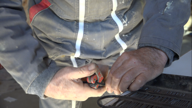
- Put the metal rods back into the feeders, they serve as stoppers for the grid pipes. If the grid pipes are pushed all the way down to the bottom of the feeder, the heat transfer fluid won't get through!
- Insert each tube into the corresponding feeder
- Hold the grids and feeders with iron wire in between.
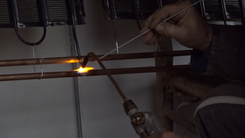
- Braze the grid pipe/feeders interfaces, making sure to braze all around the pipe. As the grid pipes are made of tinplate, the solder is made of brass or silver to avoid melting the metal.
- Braze the blind ends of the feeders.
- Remove the two metal rods that were used to stop the pipes from the grids.
- Shake the frame to remove potential solder impurities.
- Perform a "Riké" solder leak test. Moisten one thumb and put it at the entrance of one of the feeders, suck it up with your mouth and put your tongue on the 2e nurse. The tongue must stay stuck. Otherwise review the solder joints.
The feeders may be on the top or bottom of the frame, this does not change the proper operation of the panel. To be adapted according to the installation of each one.
Étape 8 - Installing the grids in the frame
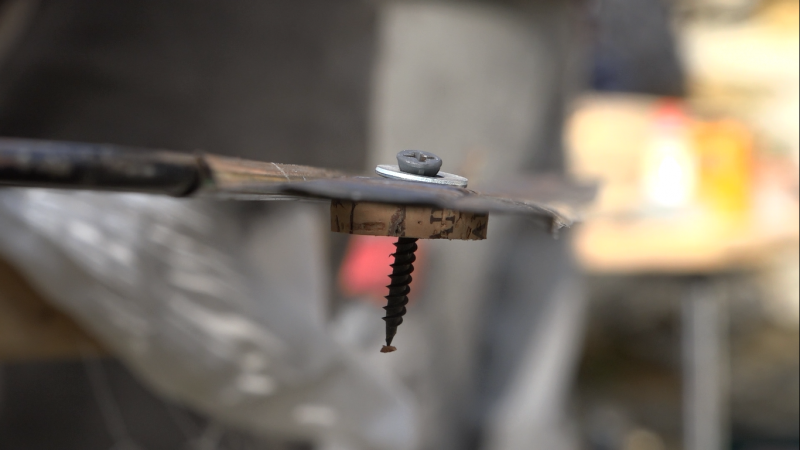
To concentrate heat on the drids, it must not be in direct contact with the door metal sheet. They are spaced by cork spacers. Cork is rot-proof and resistant to high temperatures.
- Cut corks into 5mm thick slices with a cutter.
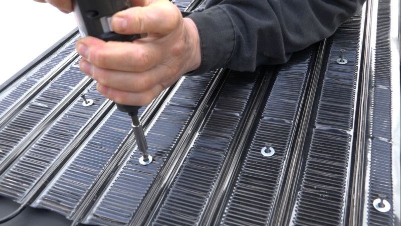
- Thread a washer onto a screw and pass it through the blades of the grids then into a cork washer. The order of the elements must be as follows: screw head, washer, grid, cork washer. This forms a pad.
- Prepare all the grids assembled with a pad every 30 cm. The objective is that the grid is close to the bottom of the frame without ever touching it. Adjust the number of pads according to the situation.
- Clean the panel.
- Position the grids and feeders in the frame.
- Screw the studs to the panel without overtightening.
- Make sure that the grids do not touch the bottom metal sheet, deform the grids if necessary.
- Paint everything that is not black in black (screw head, washers, feeders...)
Étape 9 - Panel closure
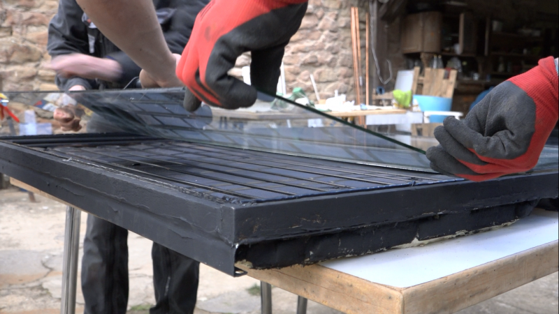
To create a greenhouse effect and limit convection between the grille and the outside, the panels will be closed with glass. Glassmakers get rid of old windows, especially double-glazing, by asking them nicely they can be recovered free of charge. Ideally, a glass thickness of 4mm is required for vertical panels and 5mm for inclined panels, more subject to hail and bad weather. It is not necessary to have thicker glasses, it reduces their performance.
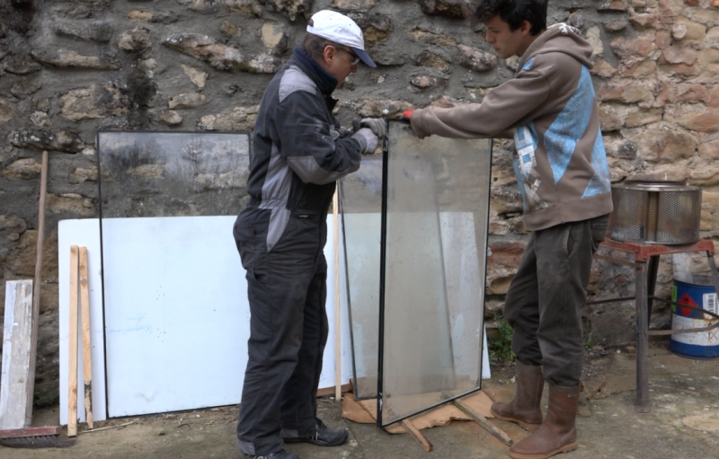
- Recover windows, to prevent them from breaking move the windows and glasses on the edge and not flat. To work with glass you must protect yourself: long sleeves, gloves and glasses.
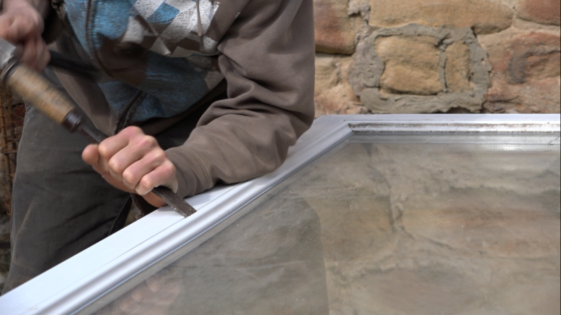
- Remove the glazing beads, slide a chisel or screwdriver between the window frame and the glazing bead on the inside of the window, tap with a hammer to separate the two and then remove the glazing bead by hand. Do the same for the other sides.
- The glazing is wedged on the sides. Remove the shims with a plier. By moving the window frame slightly away from the glass, it is easier to remove the shims, be careful not to force the glass too much as this may cause it to burst.
- Recover the glass or double glazing
- If it is double glazing, separate the two panes. Slide a cutter blade into the seal against the glass. Work standing upright, with the vertical glass on battens, moving the cutter from top to bottom. Swivel the glass to always work in this position, from top to bottom. I broke three windows while working flat and none vertical! Remove the seal in the same way for the second pane of double glazing
- Ideally it is necessary to work with windows which do not have anti-UV treatment, which limits the entry of the rays in the panel. Windows with UV treatment have a slight reflection. If you want to compare two panes, put them side by side in front of a white background, if it is tinted on one side, there is anti-UV treatment.
- To clean the remaining seal on the glass, place it flat on a table and pass a cutter blade at 45°. A rag with a little acetone will remove the last remains.
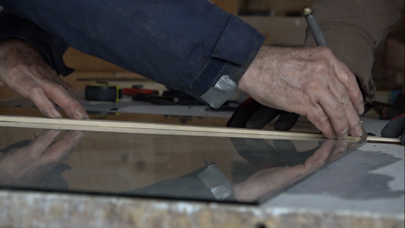
- Measure the width of the frame, between the two cleats, remove 1cm, and cut the glass to this measure. The glass is 1/2cm shorter on each side, so that it does not break when the panel is placed on the edge. To cut a window, trace with a diamond the cutting line then wipe a cloth with petrol. Position the cutting line on the edge of the table, firmly grasp the edge to be broken and snap it in a downward movement. The cut is most obvious when the part to be removed is at least 10 cm and is not too long. If you must cut a glass in length and width it is better to start with the width then the length.
- Cut the number of panes required to completely cover the panel.
- Clean the windows carefully, especially the side that will be inside the panel because you will not be able to do it once closed.
- Make a bead of black PU putty on the frame and carefully place the glasses one by one without pressing them, do not crush the beads. To avoid condensation, the panels should not be completely sealed.
- Pass the sander with a lamella disc over the edge of the glass to break the angle and not cut yourself.
- Make a black PU seal between the edge of the frame and the glass and smooth it with a finger soaked in soapy water.
- Make a black PU seal between the glasses and smooth it in the same way.
- The solar thermal panel is finished, well done, just let it dry and install.
Étape 10 - Additional panels
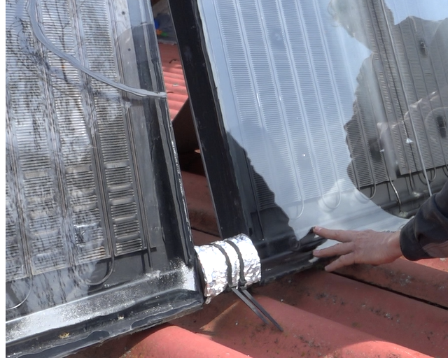
Depending on the hot water requirements and the amount of sunlight, several solar thermal panels may be required. To make additional panels, repeat the previous steps. However, unlike the blind panel, the feeders must be through, i.e. the two copper pipes, hot and cold water, must protrude at the bottom of the frame on each side. The diameter must increase by 2mm in each additional panel: 12mm for the blind panel, 14mm in the second, 16mm in the third, etc. Care must be taken to properly connect the hot water feeders between them and also for cold water feeders.
- Connect the feeders with hoses.
- Insulate the feeders and their holes through the panels.
Étape 11 - Installation
Orientation
To capture maximum solar energy, calories, the solar panel(s) must be perpendicular to the sun's rays for two reasons :
- By being perpendicular to the rays the energy density is higher, the more the angle increases, the more the "number" of rays captured will be reduced per unit area. In other words, the apparent surface of the panel, seen from the sun, is reduced with the angle.
- The glass reflects the rays, if the rays arrive perpendicular to the glass, all enter the panel, the more the angle increases, the higher the proportion of reflected rays is.
Solar panels are rarely mobile and their angle is therefore fixed to the installation. Solar power is much stronger in summer than in winter, not to mention the length of days. Solar energy is at least three times more important in summer than in winter (see tutorial energy in the home), so the panels are sized and oriented for the most critical period: winter.
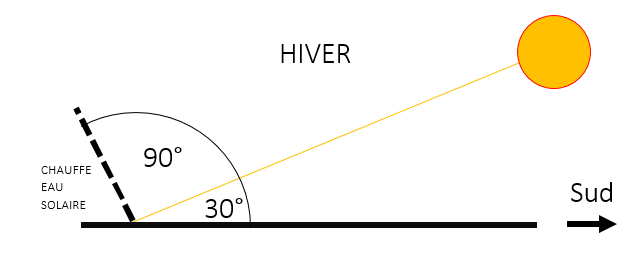
In the middle of winter, in France, the sun has a zenith at 30° with the horizon, this is its maximum height. In summer, at the same latitudes, it rises to 60°. Ideally, the panels will be installed perpendicularly to the winter sun rays, so 90°+30°=120°. They form a 120° angle with the horizon, south oriented (see scheme) . Otherwise, to limit the losses, one can put them vertically against a wall, it is more interesting and less dangerous than on roofs.
In summer, the solar power being much more important, the angle does not matter, the panels will quickly be very hot, even too much. A shading is interesting to limit overheating, a cap on a vertical panel does very well.
Plomberie
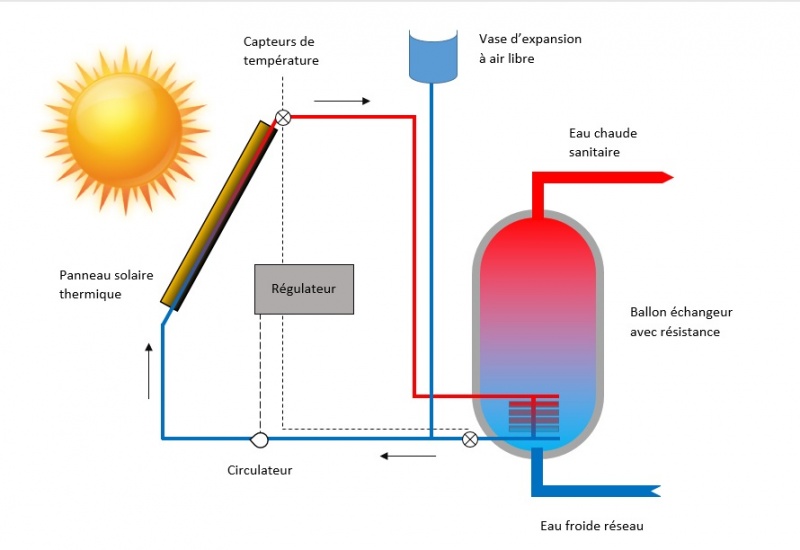
The solar thermal panels must be positioned as close as possible to the hot water tank to minimize heat loss.
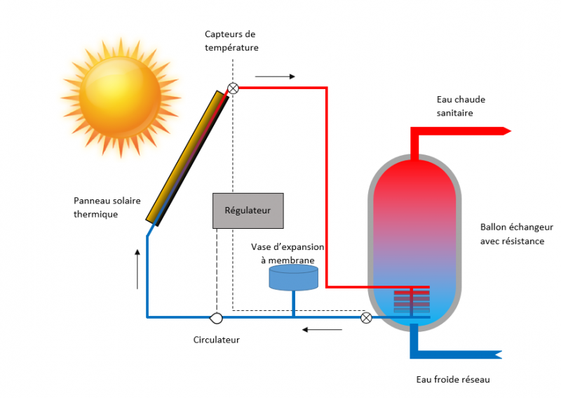
The panels must be connected to an exchanger tank. In addition to the standard electrical resistance, an exchanger passes the heat transfer fluid through the storage tank to transfer heat from the panels to the domestic water. You can find these exchange tanks in DIY stores. They cost 15 to 30% more than 100% electric balloons but will pay for themselves very quickly. Otherwise, some good tutorials allow you to make them yourself from a classic tank.
The system must be equipped with a regulator and a circulator. In our case the circulator is switched on when the temperature of the panels is 10°C higher than that of the storage tank, it is switched off when this difference is less than 5°C. This prevents the balloon from cooling at night or when the sun is shy. The tank is also equipped with an expansion vessel to absorb the expansion of the heat transfer fluid on sunny days. These elements are generally supplied with the solar heat exchangers. You can also make them yourself.
It is advisable to use a heat transfer fluid in the system. If it is used in winter it must be antifreeze, otherwise the system must be drained.
Étape 12 - Solar heating
It is possible to use the same solar thermal panel system in low temperature heating. The heat transfer fluid from the panels is fed directly into the heating pipe network in the floor or walls. However, in solar energy, heating is much less obvious than domestic hot water. Indeed, for heating, a maximum of energy is required when it is least available: in winter, when the need for domestic hot water is spread over the whole year. Moreover, the energy required for heating the house is 6 times greater than that of hot water (see tutorial energy in the home), so it will require 6 times more panels for heating than for hot water.
For example, depending on the year, Riké covers 10 to 30% of its heating needs with 14m² of panels, while it covers over 90% with 6m² of panels dedicated to heating its 350 litre hot water tank.
A simpler solar heating solution to implement was documented in February, it is a [Solar heating slate version
Étape 13 - Contenu pédagogique à télécharger
Vous pouvez télécharger une fiche pédagogique créée par le Low-tech Lab à l'occasion de l'exposition "En Quête d'un Habitat Durable" dans la partie "Fichiers" du tutoriel (onglet au niveau de la section "Outils-Matériaux".
Notes et références
This section gathers the most frequently asked questions about this tutorial and the progress of the Low-tech Lab's thinking on these topics.
Comment gérer les fluides frigorigènes ?
Les fluides frigorigènes contenus dans les réfrigérateurs peuvent avoir un fort impact sur l'environnement. Ils ont un fort potentiel de réchauffement climatique et, lorsqu'ils contiennent du chlore ou du fluor, ils participent à la déterioration de la couche d'ozone. Pour connaître le fluide contenu dans votre réfrigérateur en l'absence d'étiquettage, un repère simple est sa date de fabrication (according to Règlement Européen F-gas 517/2014).
- If it dates from before 1995, it probably contains chlorofluorocarbons (CFCs - fluids R11 and R12), whose global warming potential is up to 10,000 times that of CO2. CFCs have been banned in the European Union since that date.
- 'Between 1995 and 2010, the mainly authorised fluids are hydrochlorofluorocarbons (HCFCs - R22 fluids), whose global warming power is up to 2000 times that of CO2.
- The period 2010 - 2015 corresponds to a transition period during which the manufacture of new equipment containing HCFCs is prohibited. In 2015, the presence of HCFCs in equipment is prohibited.
- If built after 2015, it may contain :
- hydrofluorocarbons (HFCs - R134a) whose warming potential is 1,500 times that of CO2. These fluids will be banned in new equipment from 1 January 2022.
- Hydrocarbons such as isobutane (R600) and propane (R290). Their contribution to greenhouse gases corresponds to 3 times that of CO2. There is no legal restriction on their point source release into the atmosphere.
- Other fluids are being tested, such as CO2 or ammonia (NH3).
To avoid releasing these gases into the atmosphere, several solutions exist:
- Collect a refrigerator grill from an approved organization for their decontamination.
- Make a circuit to capture heat from other materials. This tutorial allows you to make one from copper tubes. You can also use a black pipe as in this video.
Pourquoi séparer le double vitrage ?
Each pane of glass reflects some of the radiation. The choice was therefore made to lose insulation in order to gain thermal input.
Quel danger de contamination par légionelles ?
The solar thermal panels are associated with an exchanger tank which has a resistance to take over during periods with less sunlight. This ensures that the minimum temperature required to kill legionella bacteria is respected: these bacteria responsible for legionelosis stop reproducing at 55°c and die at 60°c.
Références
- Tutorial directed by Camille Duband and Clément Chabot for the Low-tech Tour France, in April 2018.
- These thermal solar panels have been developed and optimized by Eric Lafond, alias Riké for more than fifteen years. There are many installed between the Isère and the Drôme.
- The tutorial was carried out in the collective of the Grand Moulin, in Saint Lattier in Isere.
- https://fr.wikipedia.org/wiki/Chauffe_eau_solaire
- https://fr.wikipedia.org/wiki/R%C3%A9flexion_(optical)
- https://fr.wikipedia.org/wiki/Coefficient_de_Fresnel
- https://www.energieplus-lesite.be/index.php?id=11278#c5928+c20968213+c20968253
Like all the work of the Low-tech Lab, this tutorial is participative, do not hesitate to add the modifications which seem important to you, and to share your achievements in comments. If you wish to help us, you can answer to this form. Whether or not you have made this low-tech, your answer will allow us to improve our tutorials.'.
Thanks in advance for your help !
Published

 Français
 English
 Deutsch
 Español
 Italiano
 Português