(Page créée avec « This step consists of connecting the solar collectors (refrigerator grid) to the heat transfer fluid circuit via two feeders (copper tubes). The feeders must have a diamet... ») |
|||
| Ligne 161 : | Ligne 161 : | ||
|Step_Picture_05=Chauffe_eau_solaire_Grille_et_nourrice_-_assemblage.png | |Step_Picture_05=Chauffe_eau_solaire_Grille_et_nourrice_-_assemblage.png | ||
|Step_Title=Assembling the grid and copper pipes (feeders) | |Step_Title=Assembling the grid and copper pipes (feeders) | ||
| − | |Step_Content= | + | |Step_Content=This step consists of connecting the solar collectors (refrigerator grid) to the heat transfer fluid circuit via two feeders (copper tubes). The feeders must have a diameter equal to the sum of the diameters of the pipes they feed, in addition, in our case, 3 pipes of 3mm inside diameter, it is necessary a feeder of at least 9mm inside diameter. |
| − | * | + | *Position the grids on the frame, in the following direction, the blades in opposition to the sun's rays once the frame is vertical. If necessary, re-cut the grids to the correct size. |
| − | + | Each grid will be connected to two feeders, one with a "cold" water inlet and the other with a "hot" water outlet. | |
| − | * | + | *For each grid, cut the pipe with a pipe cutter about 10 cm from the grid and the other about 15 cm from the grid. It must be possible to fit each tube in a different feeder in the same plane. |
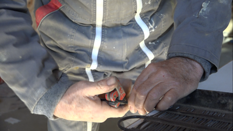
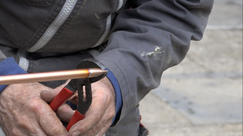
| − | * | + | * Deburr the cuts |
| − | * | + | *Carefully clean the tubes cut to a few centimetres with sandpaper. There must be no paint left to solder successfully. |
| − | * | + | *Cut a passage in the frame to get the feeders out. |
| − | * | + | *Cut 2 copper pipes, the feeders, so that they protrude about 15 cm from the panel |
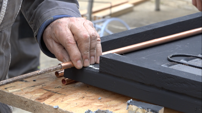
| − | * | + | *Position the two feeders. One will receive the "short" hot water pipes, the other the long cold water pipes. |
| − | * | + | *Crush the ends of the two feeders on the blind side of the frame, the one by which the feeders do not go out. |
| − | * | + | *Mark with pencil the place where the pipes and feeders meet. |
| − | * | + | *Mark with a needle. |
| − | * | + | *Drill the feeders to the diameter of the pipes (4mm). |
| − | * | + | *Deburr the holes of the feeders. |
| − | * | + | *Thread a metal rod about 12mm in diameter into each of the feeders with sandpaper at the end to remove the chips inside the pipes, as if to clean them. |
| − | * | + | *Put the metal rods back into the feeders, they serve as stoppers for the grid pipes. If the grid pipes are pushed all the way down to the bottom of the feeder, the heat transfer fluid won't get through! |
| − | * | + | *Insert each tube into the corresponding feeder |
| − | * | + | *Hold the grids and feeders with iron wire in between. |
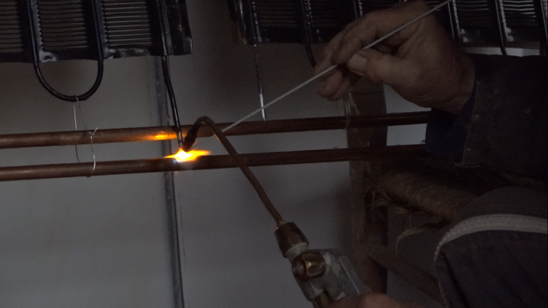
| − | * | + | *Braze the grid pipe/feeders interfaces, making sure to braze all around the pipe. As the grid pipes are made of tinplate, the solder is made of brass or silver to avoid melting the metal. |
| − | * | + | * Braze the blind ends of the feeders. |
| − | * | + | *Remove the two metal rods that were used to stop the pipes from the grids. |
| − | * | + | *Shake the frame to remove potential solder impurities. |
| − | * | + | *Perform a "Riké" solder leak test. Moisten one thumb and put it at the entrance of one of the feeders, suck it up with your mouth and put your tongue on the 2<sup>e</sup> nurse. The tongue must stay stuck. Otherwise review the solder joints. |
| − | + | The feeders may be on the top or bottom of the frame, this does not change the proper operation of the panel. To be adapted according to the installation of each one. | |
}} | }} | ||
{{ {{tntn|Tuto Step}} | {{ {{tntn|Tuto Step}} | ||
Version du 19 juin 2018 à 12:26
Description
Capturing solar energy for domestic hot water or high-efficiency heating
Sommaire
Sommaire
- 1 Description
- 2 Sommaire
- 3 Introduction
- 4 Video d'introduction
- 5 Étape 1 - Preface
- 6 Étape 2 - Grid recovery
- 7 Étape 3 - Door recovery
- 8 Étape 4 - Panel sizing
- 9 Étape 5 - Making the frame
- 10 Étape 6 - Frame painting
- 11 Étape 7 - Assembling the grid and copper pipes (feeders)
- 12 Étape 8 - Installation des grilles sur le cadre
- 13 Étape 9 - Fermeture panneau
- 14 Étape 10 - Panneaux supplémentaires
- 15 Étape 11 - Installation
- 16 Étape 12 - Chauffage solaire
- 17 Notes et références
- 18 Commentaires
Introduction
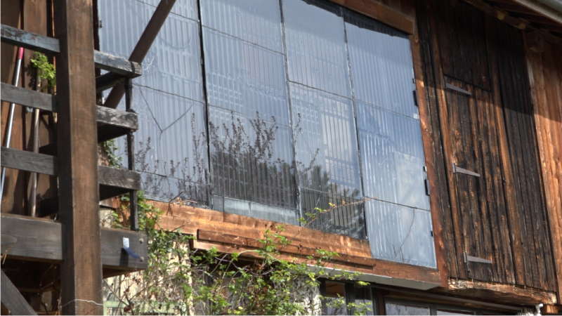
Solar panels are very efficient to take advantage of solar radiation. In our latitudes the sun is dispensed up to 1000 Watts per m². With photovoltaic panels we can capture 200 W / m², with thermal it rises to 800W / m², four times more! Solar panels are much more profitable than photovoltaic panels and much less expensive. The solution "home made" Eric Lafond offers us reach easily 500W / m² for a cost of 15 € per m².
This [1] will allow you to know the solar power you can expect to receive depending on the geographical position and of the season.
Solar thermal panels are particularly interesting for domestic hot water production. In this case they are called solar water heater.
For a two people household, you can expect 3 to 4m2 (32 to 43 sq foot) of solar thermal panels to cover 90% of the hot water needs during the year. The hot water tank will take over during the cloudy days. If there are more inhabitants, therefore more water being consumed, you need to increase the size of the solar panels. For example, 6m2 (64,5 sq foot) for 6 people.
The complete system Eric is presenting, which includes home-made panels, supply pipes, coolant, solar balloon, circulator, and a regulator is profitable in two to three years. The panels installed at his house are in their eighteenth year.
These thermal panels are designed in the same way as those of the market : an insulator and a glass window holds a solar collector traversed by a heat transfer fluid in between them. In this situation, the solar collector is the grid one can find at the back of a fridge. Insulation is provided by the doors of that same refrigerator. The glass is collected on double glazing windows. You will find many fridges in landfills or recycling areas, the double-glazing windows usually clutter the glassmakers.
A big thank to Riké, who shared with us his know-how, from his 20 years of experience in the world of energy, and to the members of the Grand Moulin collective who welcome us to the training they organized, particularly to Karine, Sylvain and Pascal. Thanks also to Jean-Loup for the accompaniment on the cutting of the glass and the solders, and to all the other volunteers of the participative building site for their help.
Matériaux
- fridge doors of similar size (support)
- grilles on the back of fridge of similar size (sensor)
- rot-resistant wooden battens (douglas, larch ...)
- 16mm-diameter copper tubes (plumbing)
- double-paneled window
- black acrylic paint
- wood screw or self-drilling screw
- washers
- polyurethane sealant
- corks
- brass solder rods and stripper
Outils
- cutter and blades
- pipe cutter
- screwdriver and bits
- hacksaw and/or grinder
- blowtorch
- handsaw and/or circular saw
- sandpaper
- solid iron tube (diameter 12mm)
- protective equipment (goggles, gloves, brazing protection glasses)
Étape 1 - Preface
Panel Orientation
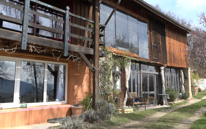
The thermal solar panels that we are creating will have to be installed direcly facing the south, ideally forming an angle of 60° with the horizon, (or on the outside wall, vertically at 90°, if the former is not possible). Rooftop usage of these panels is much less efficient in the winter and causes overheating in the summer (more details in the installation phase).
Inertia
To maximize the effectiveness of the thermic solar energy, it is necessary to minimize the inertia in the light uptake and to maximize it in the storage or the diffusion. The panels work as soon as there is a sunbeam thanks to their low inertia. The heat is kept for a long time with its great volume and its good insulation.
The pipes of the refrigerator rack have a small diameter (0,15 inches), there is so a low volume of heat transfer fluid to heat in the panel. This low inertia allows to increase fastly the temperature as soon as there is a sunbeam between two clouds and then to heat the hot water balloon. The more the diameter of the pipes increases, the more it needs time to heat a great volume of fluid and the less the system is performant.
So that the panels temperature increases as fast as possible, the volume between the insulating and the glass need to be as little as possible. Then, the thickness of the panel has to be limited, in the limit that the grid doesn't touch nor the bottom neither the glass. Otherwise, it will lose its calories by conduction with the other elements.
Temperature
The temperatures can exceed 302°F inside the panel, it is then needed to use materials resistant to heat and to UV radiations. It is impossible to use sticks or paints with solvents which don't resist to UV radiations. Here, we use putty PU and acrylic paint. For a good longevity, it is also needed to use rot-proof local wood.
On winter nights, it can get very cold inside the panel. The different materials, insulation, metal, wood and glass will expand differently between winter night and summer sun. The joints that unite them must be thick to absorb the deformation, if they are not thick enough they will tear off.
Grid
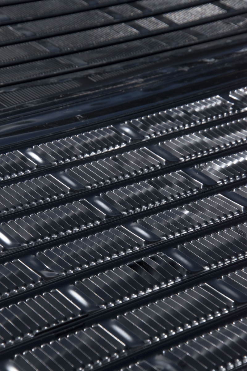
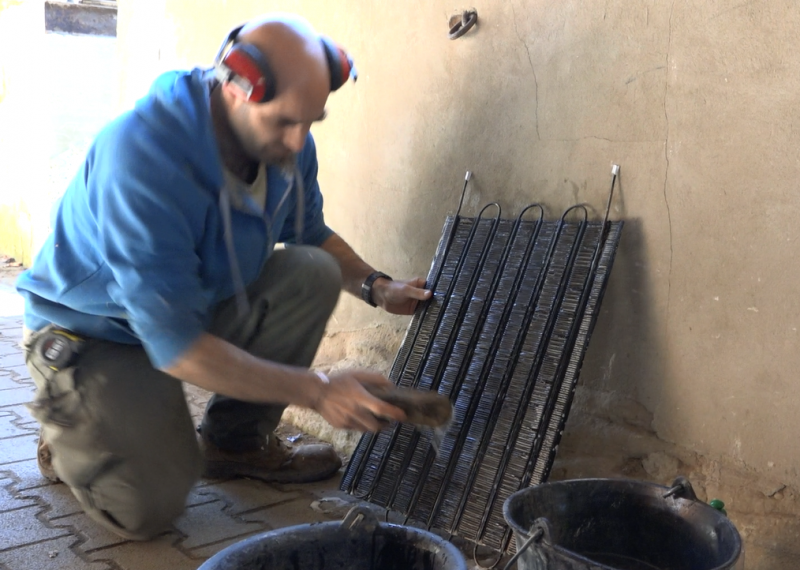
The specificity and ingenuity of these solar thermic panels are to use refrigerator grills. But beware, not all grids are good and they must be used in the right direction! The grills must be provided with cooling fins and painted black (see photo). They must not be in galvanized steel, the paint will not hold on. Similarly, some refrigerators are equipped with pipes connected by wire, the apparent surface of these grids is not sufficient, they are not interesting for this use.
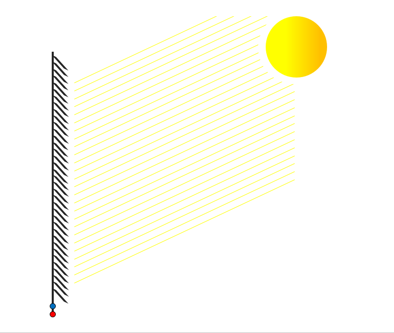
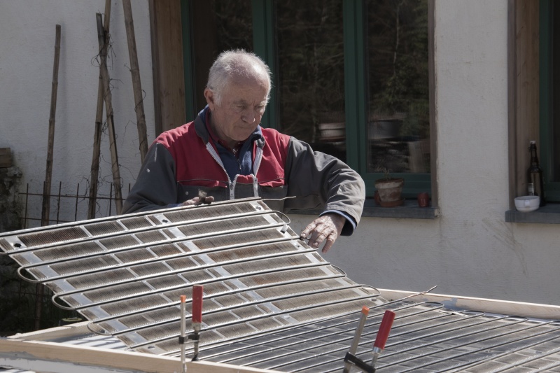
The right grilles have a direction of assembly, the fins, comparable to louvers, must capture the sun. In a sense the sun will pass through, it's bad, in the other direction it will capture the rays, it's the good sense! They must be perpendicular to the sun's rays.
Tip: take the grid and lift it between the sun and yourself, in one sense the rays will pass and not in the other.
Refrigerating gas
Refrigerator grills are covered by a refrigerant, harmful to the environment, the greenhouse effect and the ozone layer. In France the refrigerating gases must be recovered. However, there are exemptions for equipment containing less than 3 kg of fluid until 2025. The domestic installations (refrigerator and air conditioner) are degassed before continuing their upgrading process. We can open the circuit without too much conscience.
Safety
Be careful, you will do something that may involve risks.
The information and advice given in this tutorial come from joint workshops and are neither perfect nor exhaustive. If you don't have certain tools or if you don't feel competent, don't hesitate to ask around for help. Remember to wear your safety equipment, to work in ventilated areas and do not put yourself in danger. Be careful, calm, and of course critical of any false good ideas you may have ("that's how it will go...").
Enjoy!
Étape 2 - Grid recovery
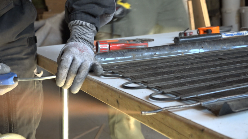
Refrigerators are numerous in waste collection centres, it is necessary to identify those which have the adequate grids (see Preface - Grid) and of the largest possible dimension. Pinching the pipes at the outlet of the compressor will limit the exhaust of refrigerant gases. Cut the pipes as close as possible to the compressor to ensure maximum length with the grid. Unscrew the grid. Wash the grid with soapy water. Blow a blower into the pipes to remove impurities. Seal the pipes with tape to prevent impurities from getting into them, as they may have a small diameter and become obstructed.
Étape 3 - Door recovery
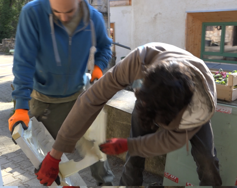
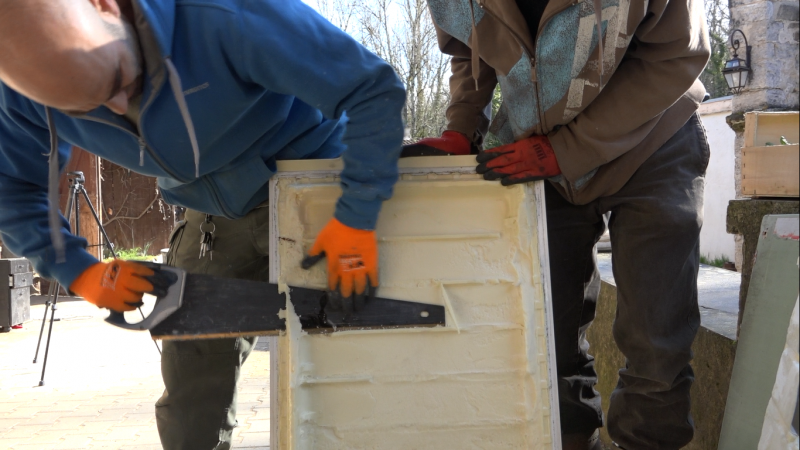
Refrigerator doors are filled with insulating foam. By recovering them and assembling them they form the back of the panel. They must be flat (and not curved), it does not matter if there is a chamfer on the edges, it will be filled with mastic.
- disassemble the refrigerator door.
- Remove all the elements except the insulation and the door sheet: seal, laminations, bolts, handles, screws, stickers... If the inside is not flat, remove it too.
- If the foam insulation is deformed, saw off the protruding parts to make the face as flat as possible. You don't need to have a beautiful surface either, it's the back of the panel.
Étape 4 - Panel sizing
Ideally, the panels should be between 1.5 and 2m², if they are larger they will be heavy and therefore more complex to install. The glass may break if the panels deform. If they are smaller it will be necessary to increase the number of panels, therefore more work to do.
Grilles of similar size, slightly smaller than the doors, should be assembled. For a panel of about 2m² you generally need 3 to 4 grilles for 2 or 3 doors. In our case we have 3 grids and 3 doors.
- Assemble at least 2-3 doors of similar sizes.
- Collect at least 3 grids of similar sizes that fit on the 3 doors.
Étape 5 - Making the frame
The refrigerator doors form the structure of the panel and are its insulator. They will be glued side by side, in the height. The difference in thickness of the doors does not matter, they are aligned on the front face, on the interior side of the panel.
- Cut the doors so that they are all the same length.
- Sand the doors
- Place the doors on two rafters, length against length, metal sheet side down.
- Make a joint along the length of the doors then glue them.
- Cut 4 battens to form a frame on the panel.
- Sand the battens
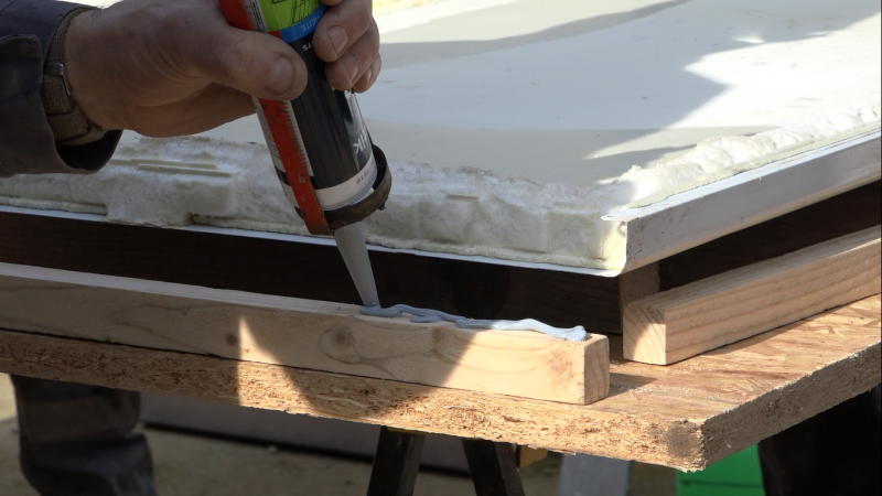
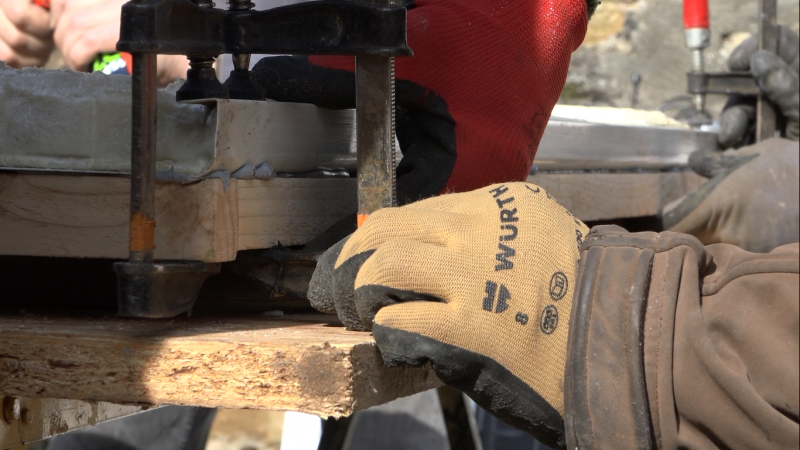
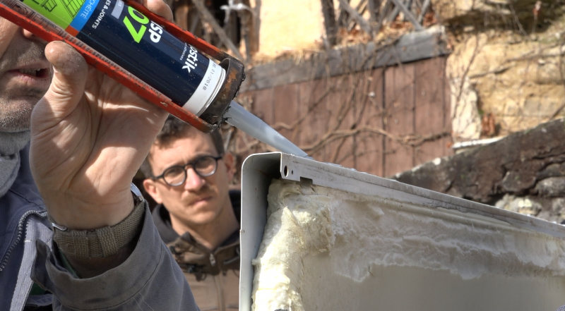
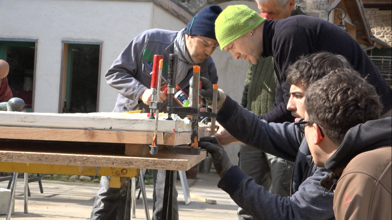
- Put putty on the width of each batten and glue them under the frame, against the sheet metal, using clamps. Do not over tighten to have a good putty thickness (>1mm).
- Let dry.
- Turn the frame over on the rafters and make seal with putty inside and outside the frame and between the doors.
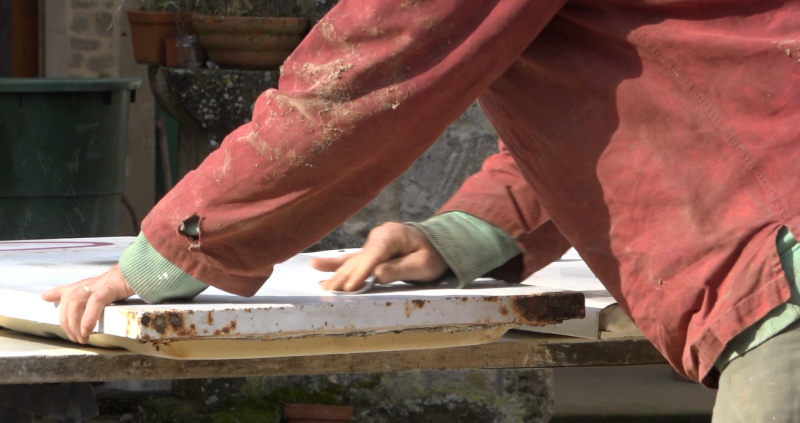
- Smooth the joints with the finger. To smooth without "lumps" and to avoid getting putty on your fingers, dip your finger in soapy water regularly.
- Let dry
Étape 6 - Frame painting
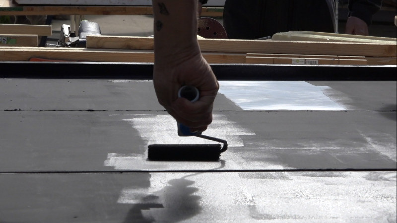
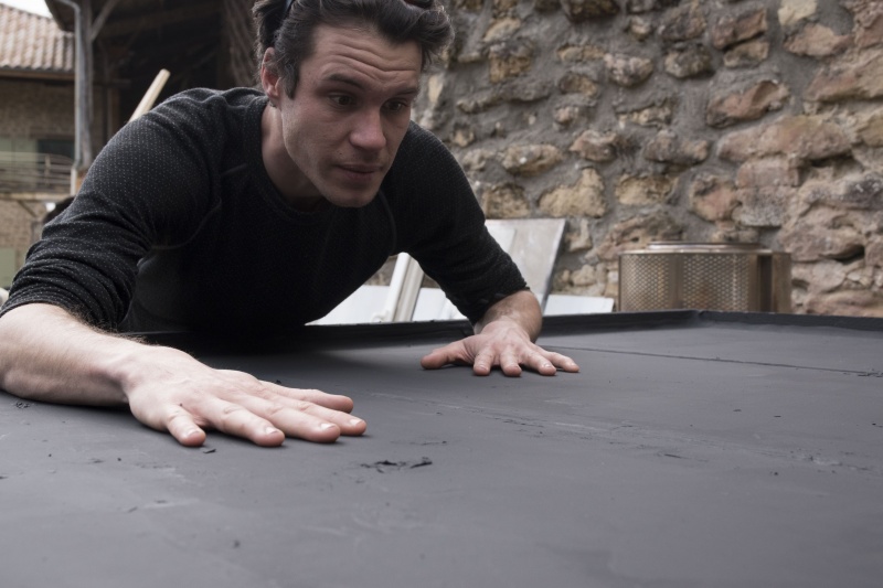
- Paint the frame, battens and door edges with mat black acrylic paint.
- Let dry
Étape 7 - Assembling the grid and copper pipes (feeders)
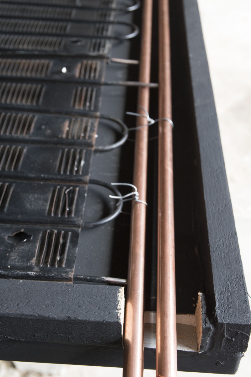
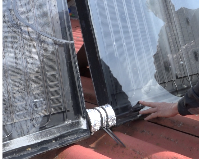
This step consists of connecting the solar collectors (refrigerator grid) to the heat transfer fluid circuit via two feeders (copper tubes). The feeders must have a diameter equal to the sum of the diameters of the pipes they feed, in addition, in our case, 3 pipes of 3mm inside diameter, it is necessary a feeder of at least 9mm inside diameter.
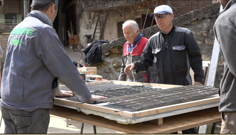
- Position the grids on the frame, in the following direction, the blades in opposition to the sun's rays once the frame is vertical. If necessary, re-cut the grids to the correct size.
Each grid will be connected to two feeders, one with a "cold" water inlet and the other with a "hot" water outlet.
- For each grid, cut the pipe with a pipe cutter about 10 cm from the grid and the other about 15 cm from the grid. It must be possible to fit each tube in a different feeder in the same plane.
- Deburr the cuts
- Carefully clean the tubes cut to a few centimetres with sandpaper. There must be no paint left to solder successfully.
- Cut a passage in the frame to get the feeders out.
- Cut 2 copper pipes, the feeders, so that they protrude about 15 cm from the panel
- Position the two feeders. One will receive the "short" hot water pipes, the other the long cold water pipes.
- Crush the ends of the two feeders on the blind side of the frame, the one by which the feeders do not go out.
- Mark with pencil the place where the pipes and feeders meet.
- Mark with a needle.
- Drill the feeders to the diameter of the pipes (4mm).
- Deburr the holes of the feeders.
- Thread a metal rod about 12mm in diameter into each of the feeders with sandpaper at the end to remove the chips inside the pipes, as if to clean them.
- Put the metal rods back into the feeders, they serve as stoppers for the grid pipes. If the grid pipes are pushed all the way down to the bottom of the feeder, the heat transfer fluid won't get through!
- Insert each tube into the corresponding feeder
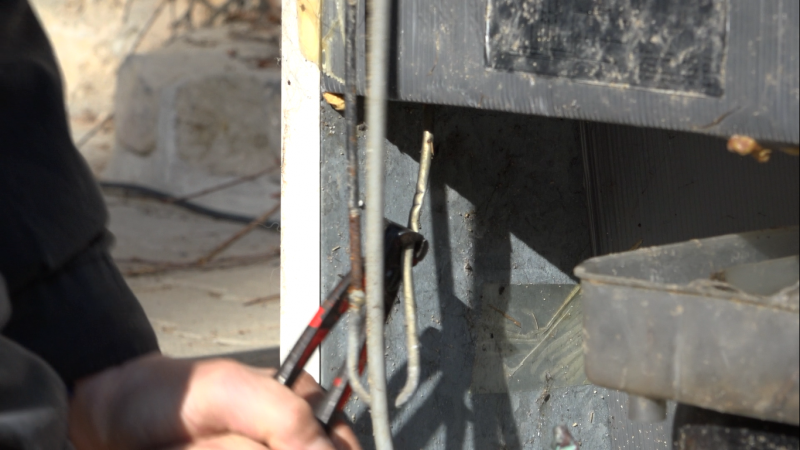
- Hold the grids and feeders with iron wire in between.
- Braze the grid pipe/feeders interfaces, making sure to braze all around the pipe. As the grid pipes are made of tinplate, the solder is made of brass or silver to avoid melting the metal.
- Braze the blind ends of the feeders.
- Remove the two metal rods that were used to stop the pipes from the grids.
- Shake the frame to remove potential solder impurities.
- Perform a "Riké" solder leak test. Moisten one thumb and put it at the entrance of one of the feeders, suck it up with your mouth and put your tongue on the 2e nurse. The tongue must stay stuck. Otherwise review the solder joints.
The feeders may be on the top or bottom of the frame, this does not change the proper operation of the panel. To be adapted according to the installation of each one.
Étape 8 - Installation des grilles sur le cadre
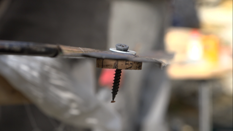
Pour concentrer la chaleur sur les grilles, elles ne doivent pas être en contact direct avec la tôle des portes. Elles sont espacées grâce à des entretoises en liège. Le liège est imputrescible et résiste bien aux hautes températures.
- Découper des bouchons en lièges en rondelle de 5mm d’épaisseur avec un cutter.
- Enfiler une rondelle sur une vis et la passer à travers les ailettes des grilles puis dans une rondelle de liège. L’ordre des éléments doit être le suivant : tête de vis, rondelle, grille, rondelle de liège. Cela forme un plot.
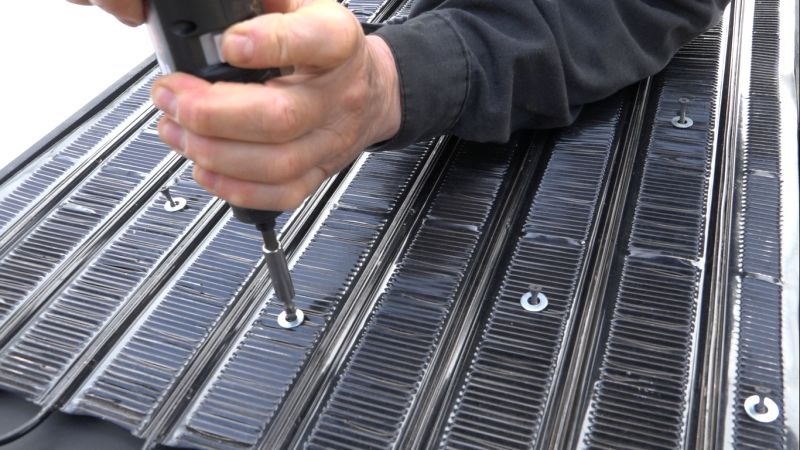
- Préparer ainsi l’ensemble des grilles assemblées avec un plot tous les 30 cm. L’objectif est que la grille soit près du fond du cadre sans jamais le toucher. Ajuster le nombre de plots en fonction de la situation.
- Nettoyer le panneau.
- Positionner les grilles et nourrices dans le cadre.
- Visser les plots au panneau sans trop serrer.
- S’assurer que les grilles ne touchent pas la tôle du fond, déformer les grilles si besoin.
- Peindre tout ce qui n’est pas noir en noir (tête de vis, rondelles, nourrices…)
Étape 9 - Fermeture panneau
Pour créer un effet de serre et limiter la convection entre la grille et l’extérieur les panneaux vont être fermés par une vitre. Les verriers se débarrassent des vieilles fenêtres, particulièrement des doubles-vitrages, en leur demandant gentiment on peut les récupérer gratuitement. Dans l’idéal, il faut une épaisseur de vitre de 4mm pour des panneaux verticaux et de 5mm pour des panneaux inclinés, davantage soumis à la grêle et aux intempéries. Ce n’est pas la peine d’avoir des verres plus épais, cela réduit leur performance.
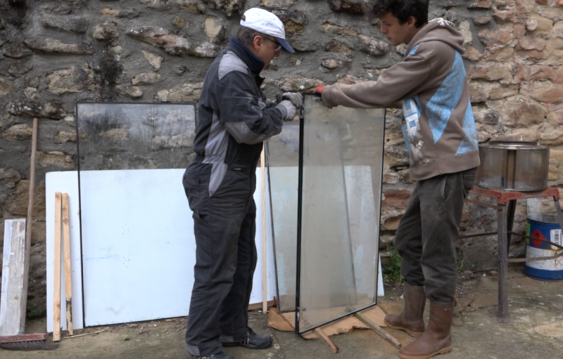
- Récupérer des fenêtres, pour éviter qu’elles se cassent déplacer les fenêtres et les verres sur la tranche et non pas à plat. Pour travailler le verre il faut se protéger : manches longues, gants et lunettes.
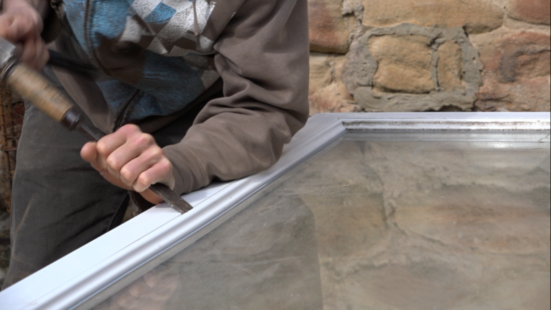
- Retirer les parcloses, glisser un ciseau à bois ou un tournevis entre le cadre de la fenêtre et le parclose du côté intérieur de la fenêtre, taper avec un marteau pour séparer les deux puis retirer le parclose à la main. Faire de même pour les autres côtés.
- Le vitrage est calé sur les côtés. Retirer les cales avec une pince. En écartant légèrement le cadre de la fenêtre de la vitre, il est plus facile de retirer les cales, attention à ne pas trop forcer sous risques de faire éclater le verre.
- Récupérer la vitre ou le double vitrage
- Si c’est un double vitrage, il faut séparer les deux vitres. Glisser une lame de cutter dans le joint contre la vitre. Travailler debout, avec la vitre verticale posée sur des tasseaux, en faisant passer le cutter du haut vers le bas. Faire pivoter la vitre pour toujours travailler dans cette position, du haut vers le bas. J’ai cassé 3 vitres en travaillant à plat et aucune à la verticale ! Enlever le joint de la même manière pour la deuxième vitre du double vitrage
- Dans l’idéal il faut travailler avec des vitres qui n’ont pas de traitement anti-UV, qui limite l’entrée des rayons dans le panneau. Les vitres avec un traitement UV ont un léger reflet. Si on souhaite comparer deux vitres, il faut les mettre côte à côté devant un fond blanc, s’il est teinté d’un côté, il y a traitement anti-UV.
- Pour nettoyer le joint restant sur la vitre, la poser à plat sur une table et passer une lame de cutter à 45°. Un coup de chiffon avec un peu d’acétone permettra d’enlever les derniers restes.
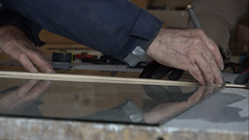
- Mesurer la largeur du cadre, entre les deux tasseaux, retirer 1cm, et couper la vitre à cette mesure. La vitre fait 1/2cm de moins de chaque côté, cela permet de ne pas la casser quand le panneau est posé sur le champ. Pour couper une vitre, tracer avec un diamant le trait de coupe puis passer un chiffon avec du pétrole. Positionner le trait de coupe sur le bord de la table, saisir fermement le bord à casser et effectuer un mouvement sec vers le bas. La découpe est plus évidente quand la partie à retirer fait au moins 10 cm et n’est pas trop longue. Si vous devez couper un verre dans la longueur et la largeur il vaut mieux commencer par la largeur puis la longueur.
- Couper le nombre de vitres nécessaires pour recouvrir entièrement le panneau.
- Nettoyer les vitres avec attention, particulièrement le côté qui sera à l’intérieur du panneau car on ne pourra plus y toucher une fois refermé.
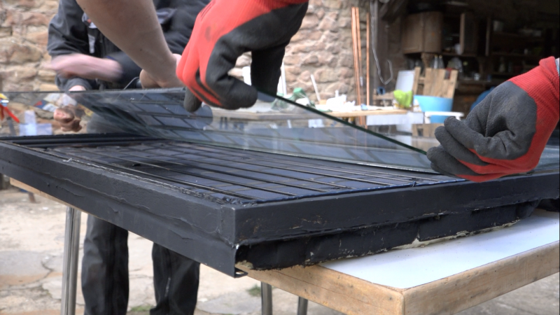
- Faire un cordon de mastic PU noir sur le cadre et déposer précautionneusement les verres un par un sans effectuer de pression dessus, il ne faut écraser les cordons. Pour éviter la condensation, il ne faut pas chercher à étanchéifier à fond les panneaux.
- Passer la ponceuse avec un disque à lamelles sur le bord du verre pour casser l’angle et ne pas se couper.
- Faire un joint PU noir entre le bord du cadre et le verre et le lisser avec un doigt trempé dans l’eau savonneuse.
- Faire un joint PU noir entre les verres et le lisser de la même manière.
- Le panneau solaire thermique est terminé, bravo, il n’y a plus qu’à le laisser sécher puis l’installer.
Étape 10 - Panneaux supplémentaires
En fonction des besoins en eau chaude et de la puissance d’ensoleillement il faudra probablement plusieurs panneaux solaires thermiques. Pour faire des panneaux supplémentaires il faut reprendre les étapes précédentes. Cependant, à l’inverse du panneau borgne, les nourrices doivent être traversantes, c’est-à-dire que les deux tuyaux en cuivre, d’eau chaude et d’eau froide, doivent dépasser en bas du cadre de chaque côté. Le diamètre doit augmenter de 2mm dans chaque panneau supplémentaire : 12mm pour le panneau borgne, 14 dans le second, 16 dans le troisième, etc. Il faut faire attention à bien raccorder les nourrices d’eau chaude entre elle et de même pour l’eau froide.
- Raccorder les nourrices avec des durites.
- Bien isoler les nourrices et leur trou de passage dans les panneaux.
Étape 11 - Installation
Orientation
Pour capter un maximum d’énergie solaire, de calories, le ou les panneaux solaires doivent être perpendiculaire aux rayons du soleil pour deux raisons :
- en étant perpendiculaire aux rayons la densité énergétique est plus élevée, plus l’angle augmente plus le « nombre » de rayons captés sera réduit par unité de surface. Autrement dit la surface apparente du panneau, vue du soleil, réduit avec l’angle.
- la vitre reflète les rayons, si les rayons arrivent perpendiculairement au verre, tous entrent dans le panneau, plus l’angle augmente, plus la part de rayons reflétés est élevée.
Les panneaux solaires sont rarement mobiles et leur angle est donc fixé à l’installation. La puissance solaire est beaucoup plus forte en été qu’en hiver, sans parler de la durée des journées. L’énergie solaire est au moins trois fois plus importante en été qu’en hiver (voir tutoriel l'énergie dans l'habitat), les panneaux sont donc dimensionnés et orientés pour la période la plus critique : l’hiver.
En plein hiver, en France, le soleil a un zénith à 30° avec l’horizon, c’est sa hauteur maximum. En été, sous ces mêmes latitudes, il monte à 60°. Dans l’idéal, les panneaux seront installés avec un angle de 60° à l’horizon, plein Sud. Sinon, pour limiter les pertes, on peut les mettre à la verticale contre un mur, c’est plus intéressant et moins dangereux que sur les toits.
L’été, la puissance solaire étant beaucoup plus importante, l’angle importe peu, les panneaux seront vite très chauds, voire trop. Un ombrage est intéressant pour limiter la surchauffe, une casquette sur un panneau à la verticale fait très bien l’affaire.
Plomberie
Les panneaux solaires thermiques doivent être positionnés au plus près du ballon d’eau chaude pour minimiser les pertes de chaleur.
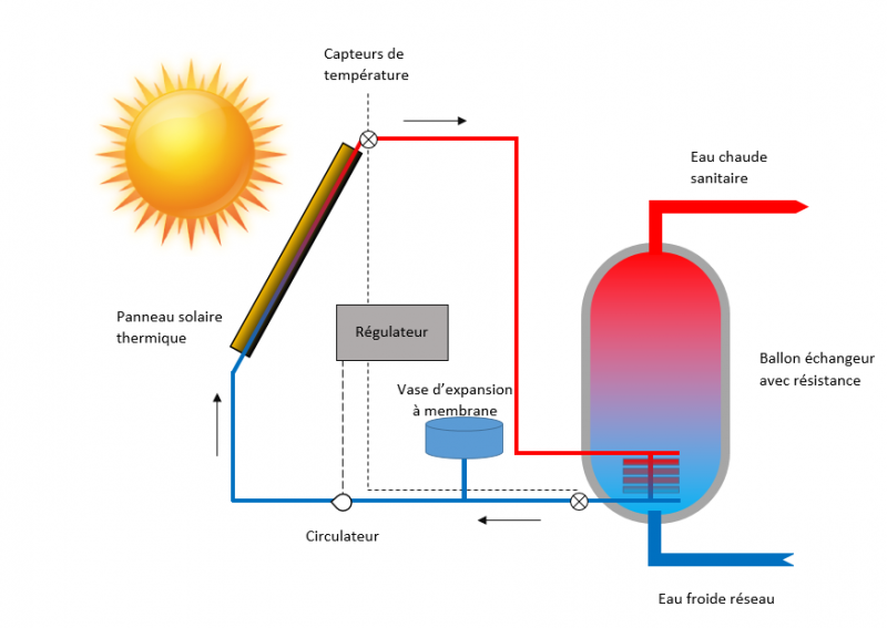
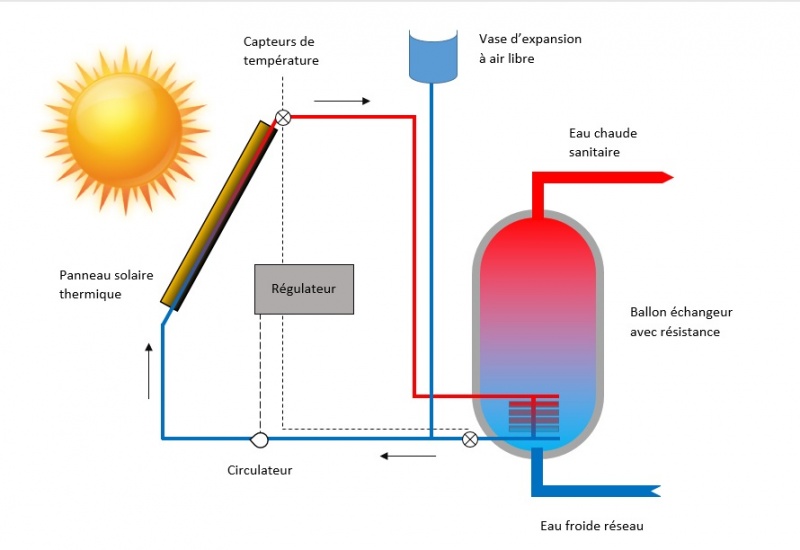
Les panneaux doivent être reliés à un ballon échangeur. En plus de la résistance électrique standard, un échangeur fait passer le liquide caloporteur dans le ballon pour transférer la chaleur des panneaux à l'eau sanitaire. On trouve ces ballons échangeurs en magasin de bricolage. Ils coûtent 15 à 30% plus cher que les ballons 100% électriques mais seront très rapidement rentabilisés. Sinon, quelques bons tutos permettent de les faire soi-même à partir d'un ballon classique.
Le système doit être équipé d’un régulateur et d’un circulateur. Dans notre cas le circulateur s’allume quand la température des panneaux est 10°C supérieure à celle du ballon, elle se coupe quand cette différence est inférieure à 5°C. Cela permet de ne pas refroidir le ballon la nuit ou quand le soleil se fait timide. Le ballon est également muni d’un vase d’expansion pour absorber la dilatation du fluide caloporteur les jours de grand soleil. Ces éléments sont en général fournis avec les ballons échangeurs solaires. On peut aussi les réaliser par soi-même.
Il est conseillé d'utiliser un liquide caloporteur alimentaire dans le circuit. S'il est utilisé l'hiver il doit être antigel, sinon il faut vidanger le système.
Étape 12 - Chauffage solaire
Il est possible d’utiliser le même système de panneaux solaires thermiques en chauffage basse température. Le fluide caloporteur des panneaux est envoyé directement dans le réseau de tuyaux chauffant dans le sol ou les murs. Cependant, en solaire, le chauffage est bien moins évident que l’eau chaude sanitaire. En effet, pour le chauffage, on va demander un maximum d’énergie quand elle est le moins disponible : en hiver, alors que le besoin en eau chaude sanitaire s’étale sur toute l’année. De plus l’énergie nécessaire au chauffage de la maison est 6 fois supérieure à celle de l’eau chaude (voir tutoriel l'énergie dans l'habitat), il faudra donc 6 fois plus de panneaux pour le chauffage que pour l’eau chaude.
En exemple, selon les années, Riké couvre 10 à 30% de ses besoins en chauffage avec 14m² de panneaux alors qu’il dépasse les 90% de couverture avec 6m² de panneaux dédiés à chauffer son ballon de 350 litres eau chaude.
Une solution de chauffage solaire plus simple à mettre en œuvre a été documentée en février, c’est un convecteur solaire, imaginé par Guy Isabel.
Pour les jours froids, un Poelito, poêle de masse à très haut rendement, est également documenté, grâce au travail de Vital Bies et de David Mercereau. Il est possible d’y ajouter un bouilleur pour chauffer l’eau chaude sanitaire. C’est le partenaire idéal des journées sans soleil !
Notes et références
- Tutoriel réalisé par Camille Duband et Clément Chabot dans le cadre du Low-tech Tour France, en Avril 2018.
- Ces panneaux solaires thermiques ont été développés et optimisés par Eric Lafond, alias Riké depuis plus de quinze ans. On en retrouve de nombreux installés entre l'Isère et la Drôme.
- Le tutoriel a été réalisé dans le collectif du Grand Moulin, à Saint Lattier en Isère
- https://fr.wikipedia.org/wiki/Chauffe_eau_solaire
- https://fr.wikipedia.org/wiki/R%C3%A9flexion_(optique)
- https://fr.wikipedia.org/wiki/Coefficient_de_Fresnel
- https://www.energieplus-lesite.be/index.php?id=11278#c5928+c20968213+c20968253
Yes
 Français
 English
 Deutsch
 Español
 Italiano
 Português