Description
Solar air heater, adaptable to any type of house, by Guy Isabel.
Sommaire
Sommaire
- 1 Description
- 2 Sommaire
- 3 Introduction
- 4 Étape 1 - Frame
- 5 Étape 2 - Background and insulation of the frame
- 6 Étape 3 - Opening the sensor input and output
- 7 Étape 4 - Optional: Rain protection
- 8 Étape 5 - Summer hatch
- 9 Étape 6 - Reflective surface
- 10 Étape 7 - Glass weatherstrip
- 11 Étape 8 - Baffle circuit
- 12 Étape 9 - Slate laying
- 13 Étape 10 - Huilage et vernissage
- 14 Étape 11 - Pose de la vitre
- 15 Étape 12 - Système clapet, partie fixe
- 16 Étape 13 - Système clapet, partie mobile
- 17 Étape 14 - Système clapet, Assemblage
- 18 Étape 15 - Installation
- 19 Étape 16 - Utilisation
- 20 Notes et références
- 21 Commentaires
Introduction
The design of this solar heating was strongly inspired by Guy Isabel, on the plans he describes in his book Les capteurs solaires à air, Eyrolles edition.
The sun transmits energy to the earth by radiation. At the equator, the radiation reaches the power of 1000 W / m², it is by comparison, the power of a small electric heater.
Solar energy is a free and intermittent energy, which is relatively simple to transform efficiently as heat, (yield easily above 60%).
This website allows to know according to the season and the geographical position, many parameters such as the maximum power per m², the angle of the sun compared to the place.
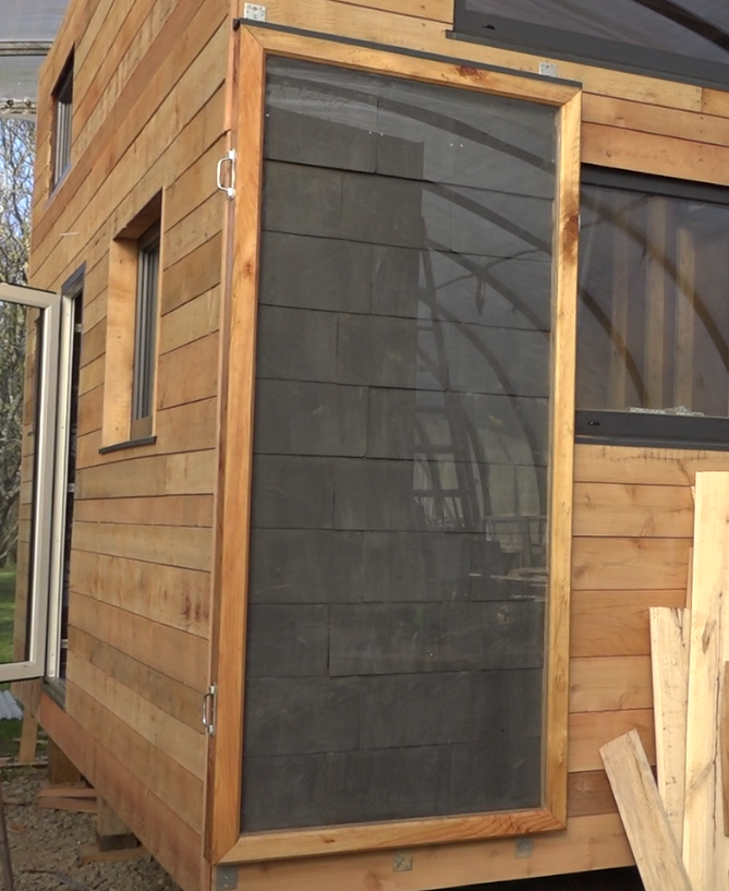
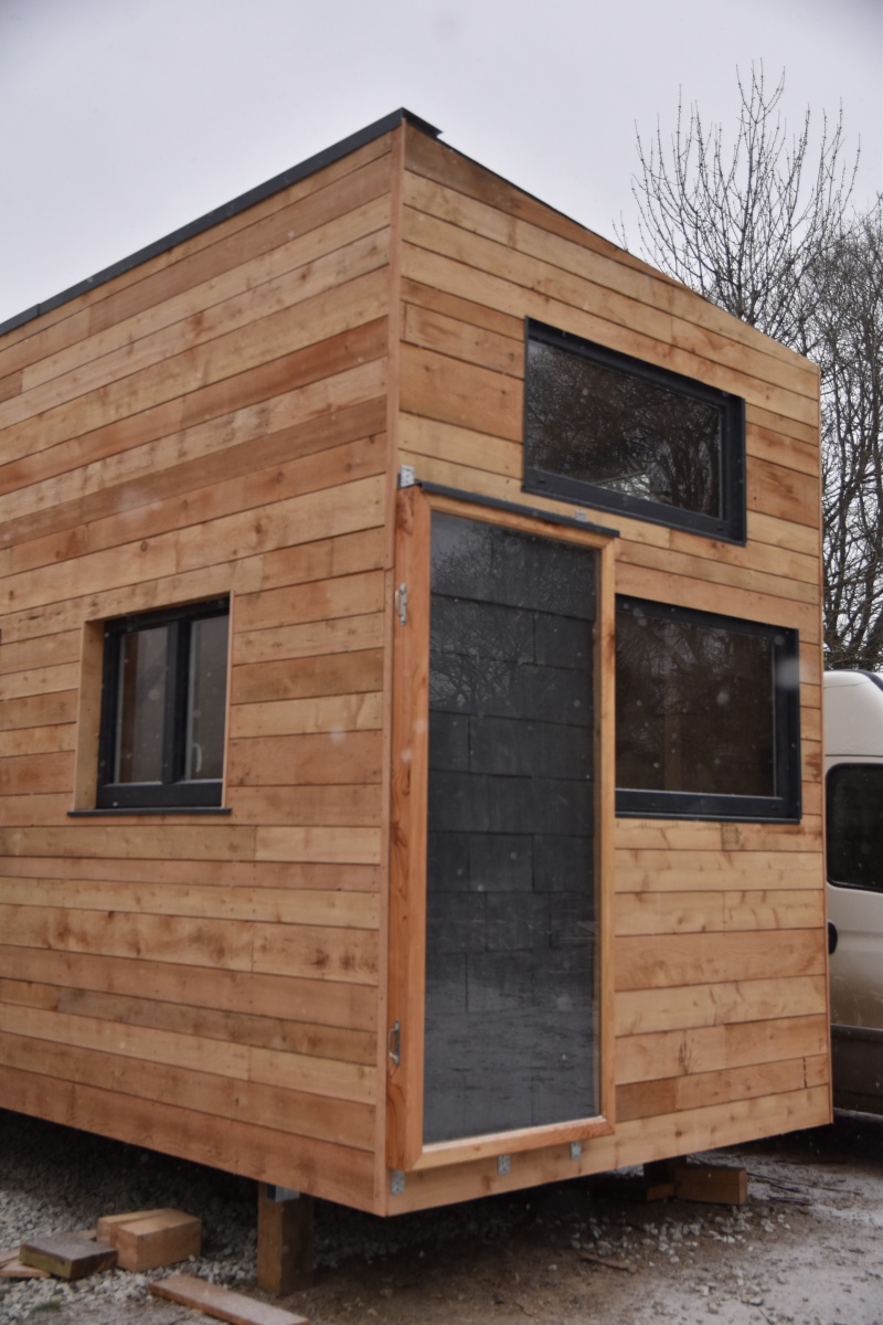
Solar air heater
Concretely, it is a question of transforming the solar radiation into heat thanks to what is called a black body (for example the very hot tar in the summer or the dashboard of a car parked in full sun).
For housing, the most common systems on this principle are solar water heaters, often installed on the slopes of roofs to make domestic hot water supplements of conventional systems.
Less known, the air sensor allows to heat the air of a room.
This tutorial presents the manufacture of an air sensor of 2 m² designed for the heating of the air of a room of 10 to 15 m² of 5 to 7 ° C winter on average, for France. It is a complement to the conventional heating system, which allows appreciable financial and ecological savings. At a cost of around € 200, it is quickly amortized.
Principle
In winter, the sensor sucks in the air from below, heats it thanks to the shaving sun, then restores it to the habitat through the high outlet, at a temperature of up to 70 ° C locally (instantly diluted in the water). ambient atmosphere).
In summer, an external hatch allows to reject the hot air of the sensor outside while aspiring at the same time the air of the habitat, thus creating a natural ventilation.
A valve connected to a thermostatic jack, allows to manage automatically and without electricity, the opening of the air circulation, only when it has reached more than 25 ° C in the sensor.
Matériaux
The tutorial presented here is 2.09m x 1.09m overall
Sensor:
- Chevron Douglas (here the final section is 95mm x 45mm)
- 2 of 2m10
- 2 of 1m10
- 15 m of douglas sheets (20mm x 53mm)
- Rigid plate (here plywood filmed, 10mm)
- Rigid insulation (here Steico plate, 22mm)
- Sika cartridge
- Silicone cartridge
- PU glue for outdoor wood gluing
- Wood glue
- Nails
- Wood screws, from 30mm to 150mm
- Comprehensive seal
- Linseed oil
- Wood varnish
- 15 m of douglas sheets (30mm x 16 mm)
- Aluminum adhesive
- Tempered glass or polycarbonate plate (1m x 2m)
- Expanded metal grid (300mm x 50mm)
- 4 screw legs (example)
- 1m of aluminum drip 100mm width (example)
- Double-sided adhesive
- Thin insulation (here parquet insulation)
- 30 to 35 slates 320mm x 220mm, thickness 3,5mm
- 8 reinforced squares, mini width 40mm
- 1 tube diameter 100mm length of the housing wall, pvc / aluminum / stainless steel for the low entrance
Valve system:
- 1 Thermostatic cylinder Vernet EL 0769
- 100mm of brass tube diameter 4mm
- compression spring length 70mm
- 1 washer
- 1 small screw
- 2 rivets
- 5 cm of copper wire diameter 2mm
- 1 domino electrician diameter 4mm
- Plumbing / gas equipment:
- 100mm of threaded brass tube 15/21
- 2 brass blind nuts 15/21
- 1 brass through nut 15/21
- 1 copper sleeve diameter 12mm
- 1 copper sleeve diameter 14mm
- 1 brass nipple 15/21
- 1 ventilation valve, here diameter 100mm
- 1 ball catch
- 1 aluminum or stainless steel tube along the wall of the house wall, diameter of the valve
optional:
- Rain barrier
- Sealant
Outils
- Wood saw
- Screwdriver / drill and wood / metal drills
- Wall stapler
- Paint brushes
- Hammer
- Cutter
- Grinder and diamond / metal discs
Étape 1 - Frame
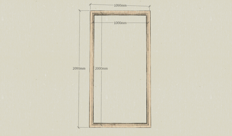
Note: Here, the frame is sized to accommodate a glass 1m x 2m by 6mm thick, a 10mm film plywood bottom and a 22mm insulating layer in STEICO. The dimensions will therefore be adapted according to the availability of each.
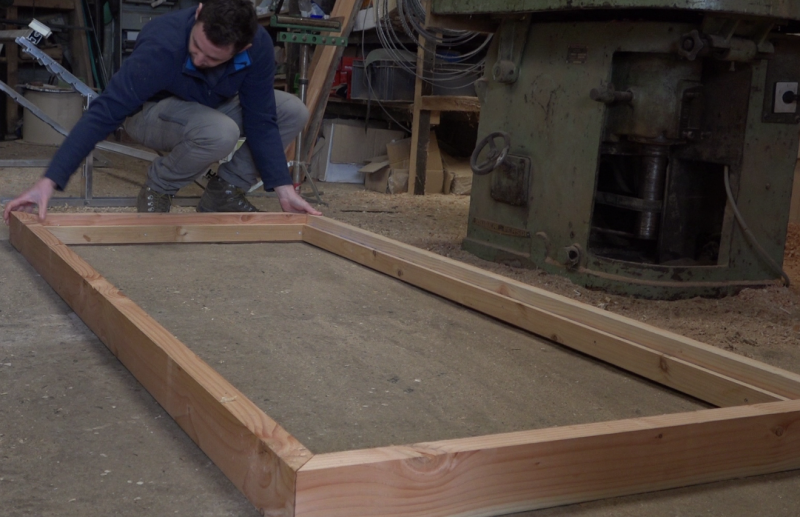
- Prepare 2 rafters of section 93mm x 45mm and 209 cm in length.
- Prepare 2 rafters of section 93mm x 45mm and 109 cm in length.
- Prepare 2 battens of section 20mm x 53mm and 209 cm long.
- Prepare 2 battens of section 20mm x 53mm and 109 cm long.
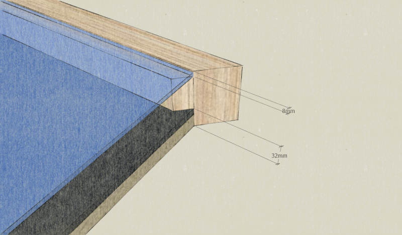
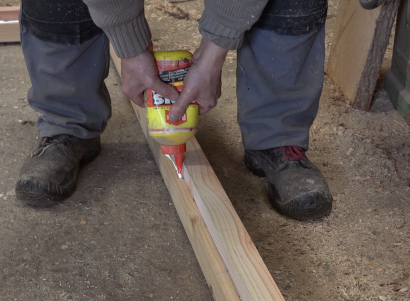
- Glue PU glue and screw the battens on the rafters associated a face of 93mm thick, 32mm from one of the edges.
Note: These 32mm correspond to the insulating thickness + filmed plywood. There is 8mm remaining on the other edge to accommodate the thickness of the glass and a seal comribande.
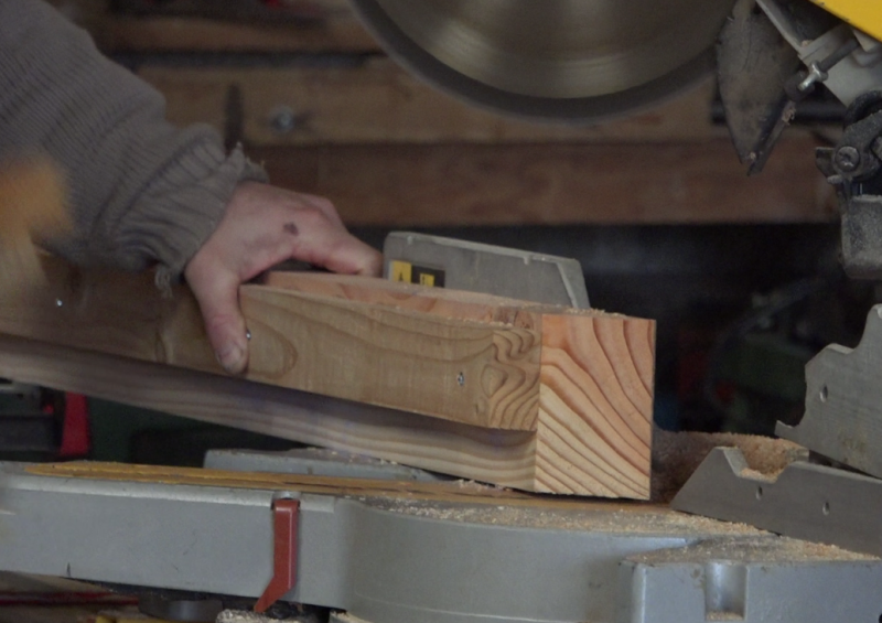
- Cut the corners of each wood profile thus obtained at 45 °, paying careful attention to the direction of the cut. The cut is made on the length of 93mm.
Note: This cut allows to find the dimension 1m x 2m of the window inside the frame.
- Assemble the frame using PU glue and long wood screws in each of the 4 corners.
Étape 2 - Background and insulation of the frame
- Prepare an area of 1m x 2m for the chosen background (here a 10mm thick film plywood).
- Prepare a surface of 1m x 2m for the chosen insulation (here STEICO plates of 22mm thickness).
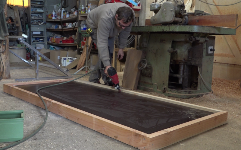
- Pull a wood glue seal on the frame battens, 32mm thick side.
- Deposit 'the bottom first' then ensure the plating with regular studding.
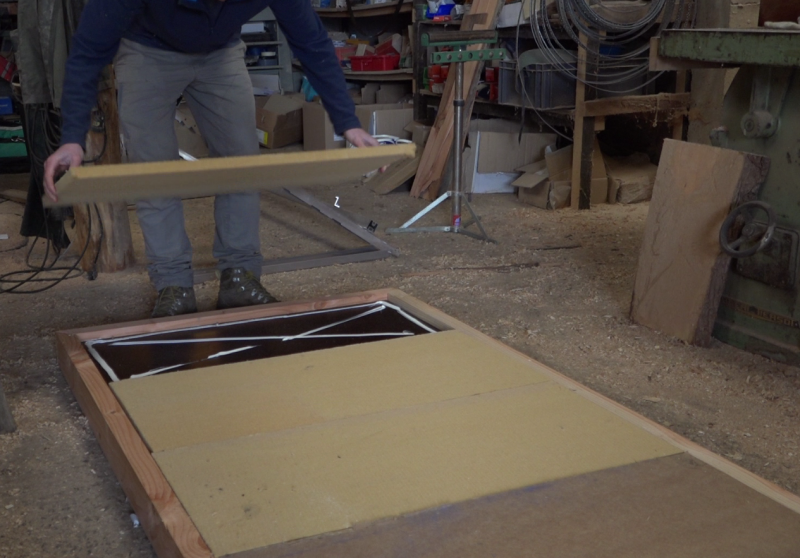
- Draw sika cords on the bottom then lay the insulation. This is the outermost layer of the frame.
Étape 3 - Opening the sensor input and output
Note: Here, the chosen ventilation flap is 100mm in diameter, so it is at this diameter that the inlet and the outlet will be made.
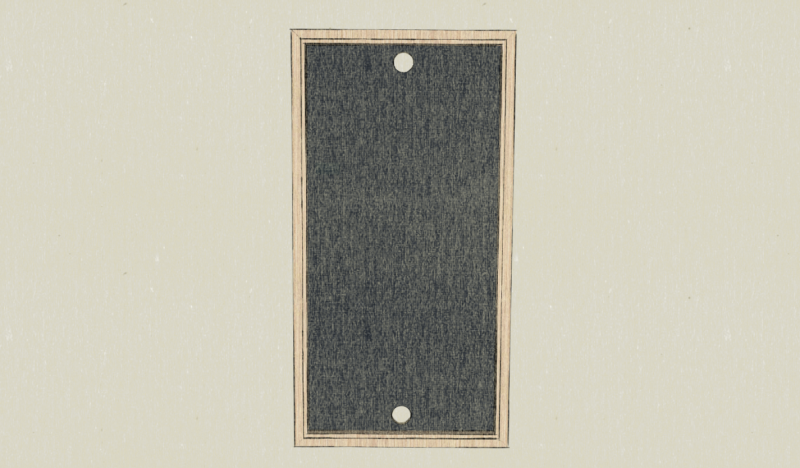
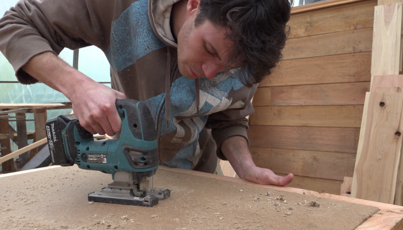
- On the central axis of the sensor, trace and cut the air inlet hole, 30mm from the batten, at the bottom of the frame.
- On the central axis of the sensor, trace and cut the air outlet hole, 30mm from the batten, at the top of the frame.
Étape 4 - Optional: Rain protection
Note: Depending on the chosen insulation, the installation of a rain screen at the back is not necessarily necessary if it is well waterproof.
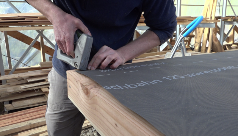
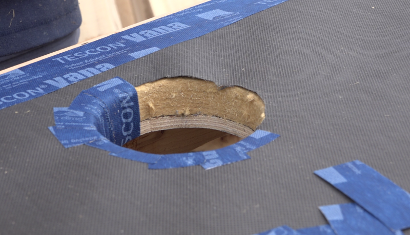
- Remove the rain cover on the insulation layer leaving a 2cm overhang on the Douglas frame.
- Staple the rain cover.
- Open the rain shield at the inlet and outlet.
- Glue a waterproof adhesive between the frame and the rain screen.
Étape 5 - Summer hatch
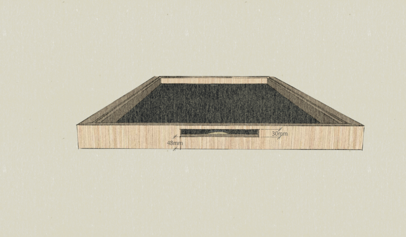
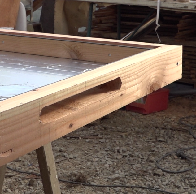
- On the upper part of the frame, open a hatch of 300mm long by 30mm wide. It is at the bottom of the water.
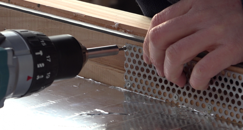
- Fix inside the anti-rodant grill
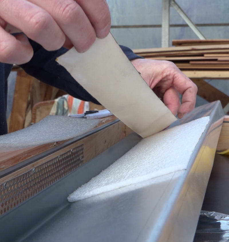
- Using double-sided tape, center and glue a rectangle of parquet insulation on the underside of the dripstone, which serves as a cover.
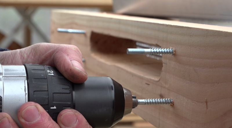
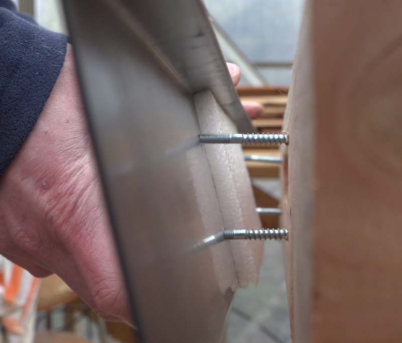
- Position 4 screws around the hatch taking care to check that the parquet insulation can be placed in the rectangle formed by the screw legs.
- Drill the drip so that it can fit on the screw legs.
- Put it aside, it will be added at the end of editing.
Étape 6 - Reflective surface
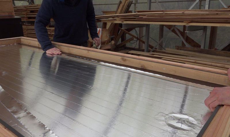
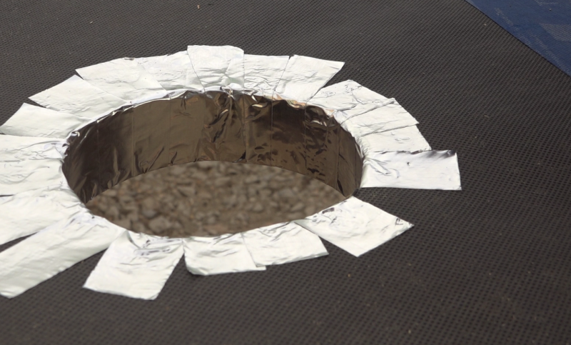
Note: In order to reduce the energy loss in the sensor, the film plywood bottom is covered with an aluminum layer to reflect the infrared radiation in the sensor.
- Line the bottom of the aluminum adhesive sensor.
Étape 7 - Glass weatherstrip
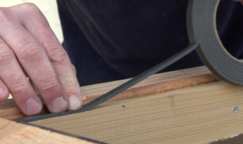
- Place an adhesive joint on the battens of the frame 1mm from the edge, all along the frame. It will serve to welcome the glass.
Étape 8 - Baffle circuit
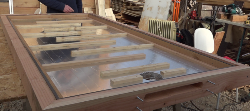
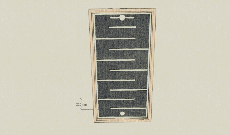
- Screw the 30mm x 16mm battens to the reflective backing in a baffle pattern.
- The baffles, by 675mm, cover 3/4 of the width of the panel.
Note: Here, the gap including 2 cleats is 220mm, this is the width of the slates used later. This spacing will allow a light recovery of each slate.
Étape 9 - Slate laying
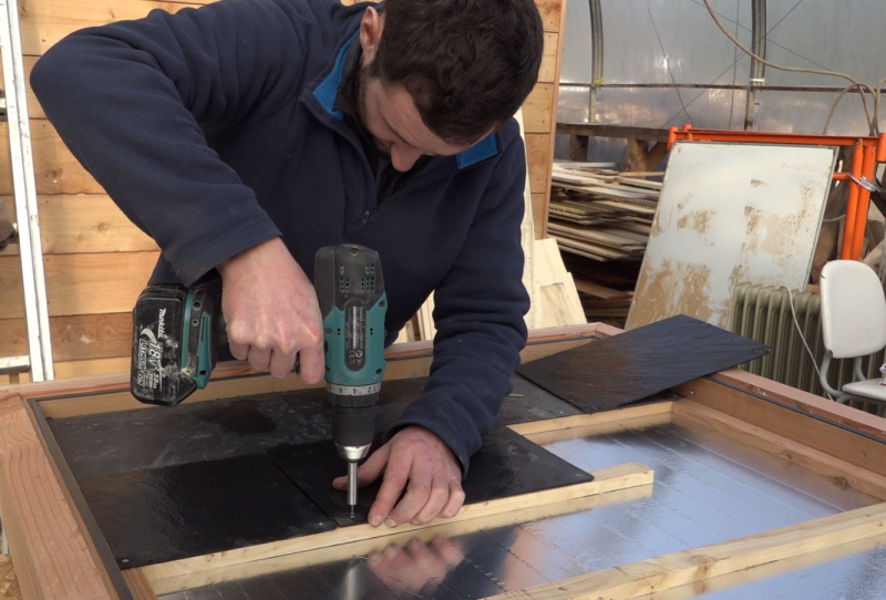
- Positionner la première ranger d'ardoises sur le niveau de chicane le plus bas.
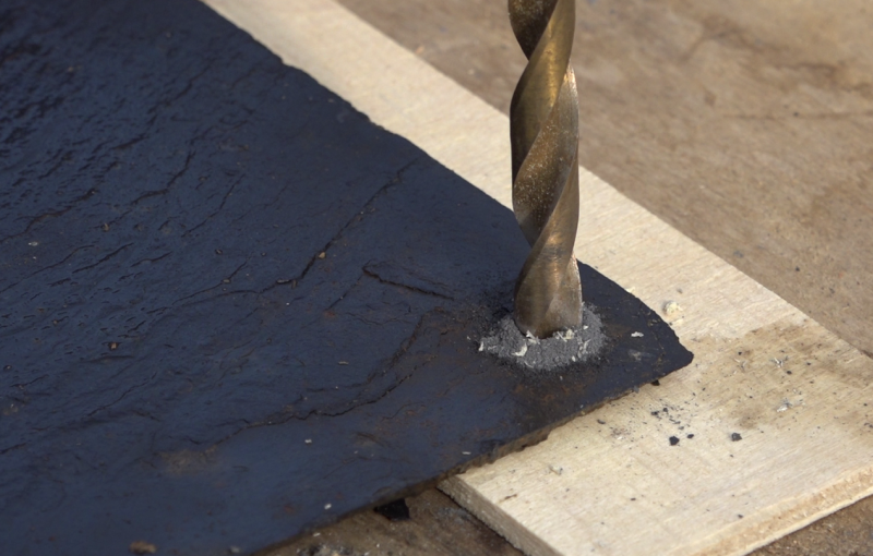
- Marquer 2 trous de perçage puis percer avec un foret de 4mm. Il est possible de fraiser légèrement le trous avec un foret plus large afin que la tête de vis soit intégré à l'épaisseur de l'ardoise.
- Si nécessaire, découper les ardoises avec la meuleuse disque diamant, une scie à métaux peut éventuellement faire l'affaire.
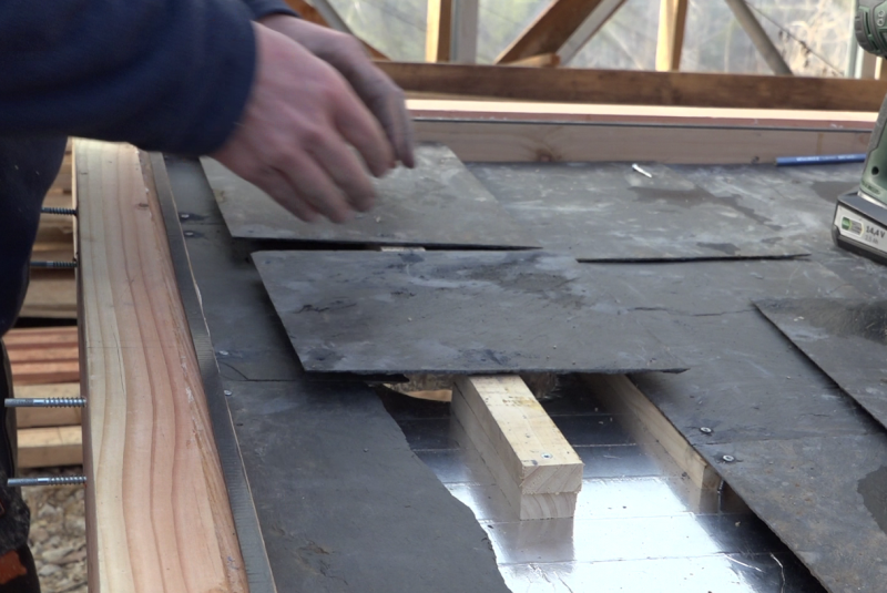
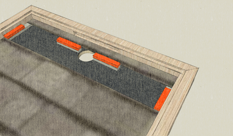
- Compléter le cadre d'ardoise en prenant soin de surélever les ardoises sur les chicanes les plus proches de la sortie (cf photo).
Remarque: La rangée d'ardoise est surélevé à proximité de la sortie afin de pouvoir évacuer l'air contenu devant et derrière les ardoises, aussi bien en hiver qu'en été par la "trappe été".
Étape 10 - Huilage et vernissage
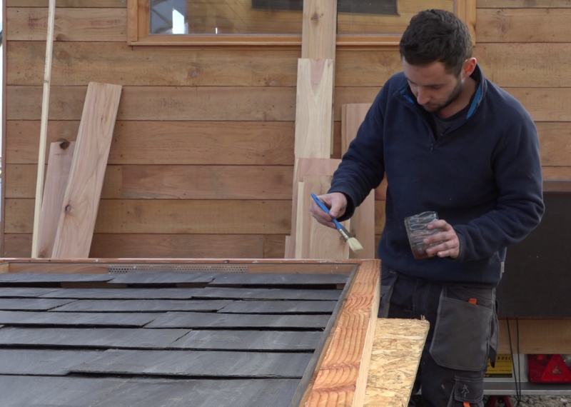
- Huiler le cadre avec de l'huile de lin.
- Laisser sécher puis vernir.
Étape 11 - Pose de la vitre
Remarque: Ici, une vitre trempée de 6mm d'épaisseur est utilisée. Il est également possible d'utiliser du polycarbonate.
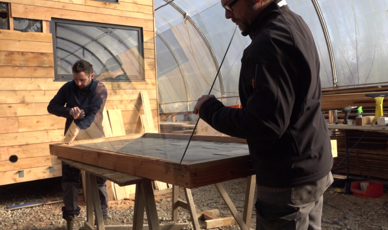
- Nettoyer la vitre.
- Préparer les "pare-closes" dans le reste de liteaux de 53mm x 20mm. Un chanfrein est effectué pour une bonne évacuation de l'eau ainsi qu'une coupe à 45° comme pour le cadre. Huiler et vernir les pare-closes.
Remarque: Les pare-closes servent à maintenir la vitre dans son logement en comprimant le joint compribande. Elles doivent donc à la fois recouvrir le bord de la vitre et prendre appui sur le cadre.
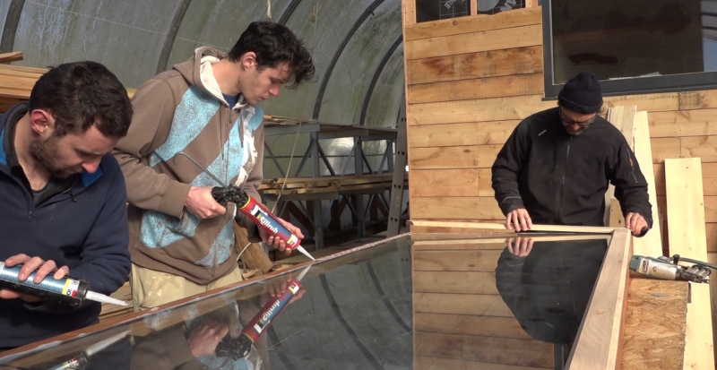
- Tirer un joint de silicone entre le joint compribande et le cadre.
- Positionner la vitre.
- Tirer de nouveau un joint silicone sur la bordure de la vitre ainsi que sur le cadre.
- Positionner et visser les pare-closes.
- Tirer un cordon de silicone sur l'arête vitre/pare-close.
Étape 12 - Système clapet, partie fixe
Remarque: Le vérin thermostatique fonctionne sans électricité. Il renferme un matériau calibré qui se dilate à partir de 25°C et se rétracte en dessous.
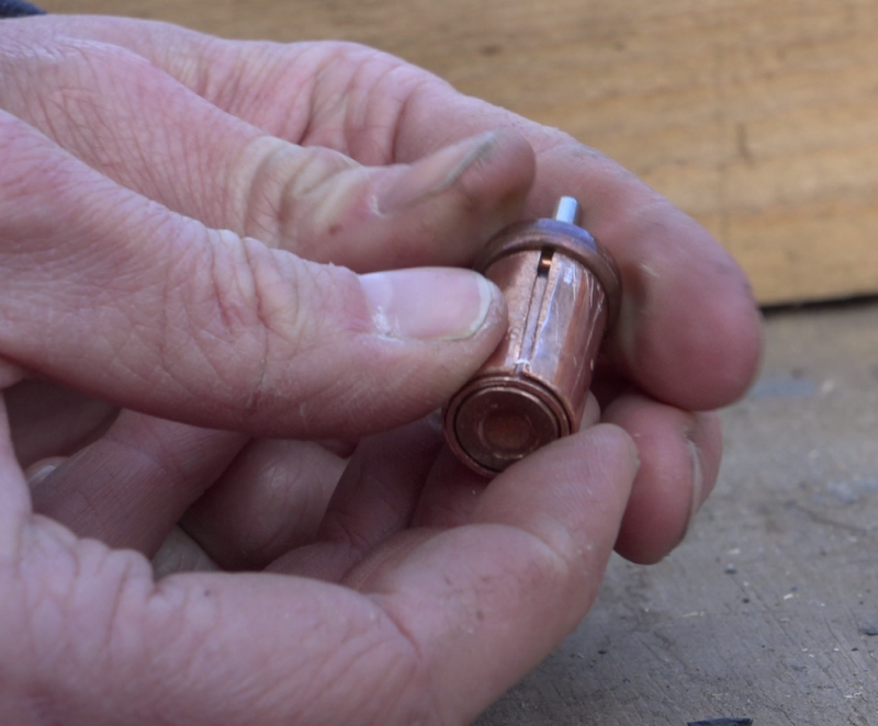
- Limer le pointage intérieur des manchons en cuivre de 12mm et 14mm
- Fendre sur une longueur le manchon de 14mm.
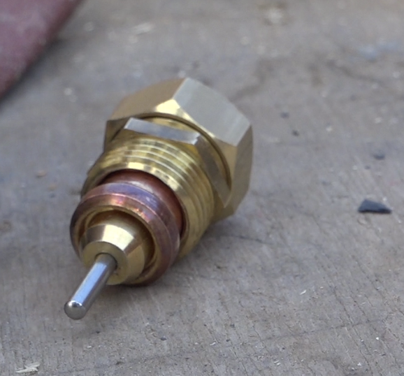
- Insérer le vérin dans le manchon de 12 mm puis le tout dans le manchon de 14mm.
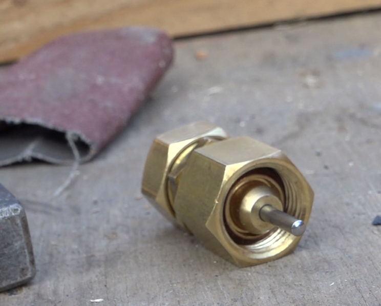
- Insérer cet assemblage dans le mamelon laiton 15/21.
- Fermer le coté du bas du vérin en visant un écrou borgne sur le mamelon.
- Visser l'écrou ouvert sur l'autre face du mamelon.
Étape 13 - Système clapet, partie mobile
- Couper 100mm de tube laiton diamètre 4mm.
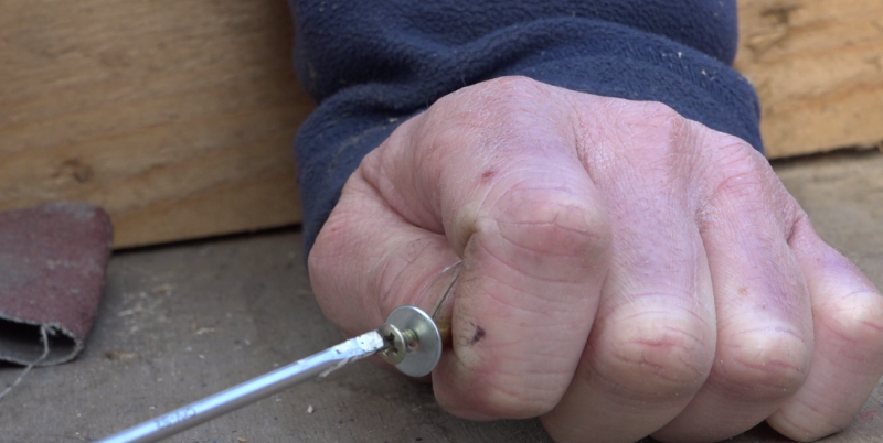
- Insérer une vis et une rondelle à l'une des extrémités.
- Percer un écrou laiton 15/21 en son centre avec un foret de 4mm.
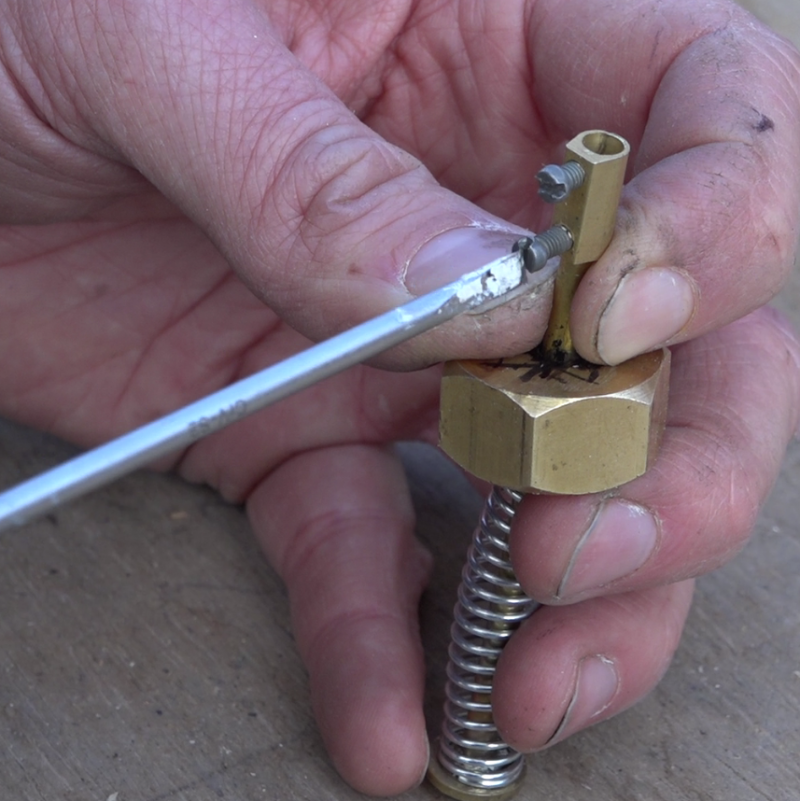
- Insérer le ressort et l'écrou percé sur le tube.
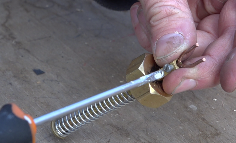
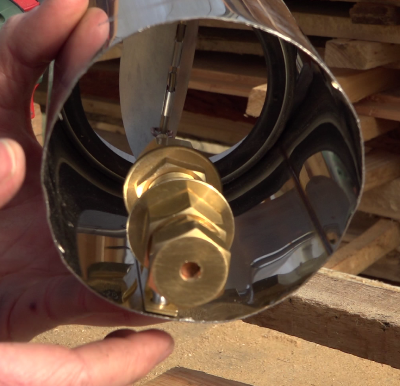
- Enlever la partie plastique d'un domino diamètre 4mm puis le visser sur l'extrémité libre du tube laiton.
- Préparer une petite fourche en fil de cuivre épais et la placer sur le domino.
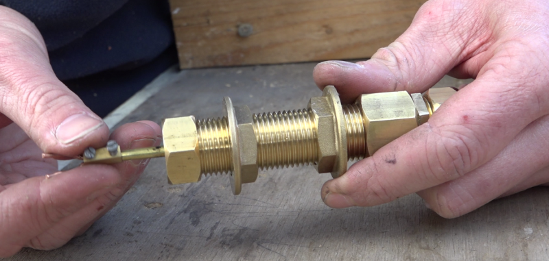
- Un tube fileté laiton 15/21 est utilisé pour contenir la partie mobile ainsi crée. Couper ce tube de tel sorte qu'une fois visser dans la partie fixe, le ressort soit légèrement comprimé lorsque le vérin est rétracté (froid).
- Assembler le tout sans oublier de passer 2 écrous autour du tube fileté.
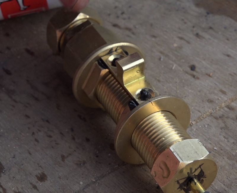
- Coller la partie fixe du loqueteau à bille sur le plat des 2 écrous du tube filetée.
Étape 14 - Système clapet, Assemblage
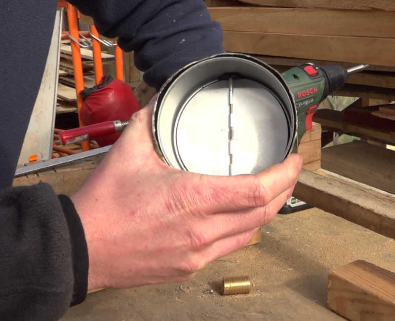
- Préparer un tube inox de la largeur de la paroi où sera installé le capteur. (ici, un tube de diamètre 100mm est utilisé)
- Positionner le clapet à l'une extrémité du tube, l'ouverture vers l'extérieur
- Repérer le positionnement du montage vérin, chaud et complètement sortie, de tel sorte que la fourche en cuivre pousse les ailettes en ouverture maximum.
- Riveter la partie bille du loqueteau à cette position.
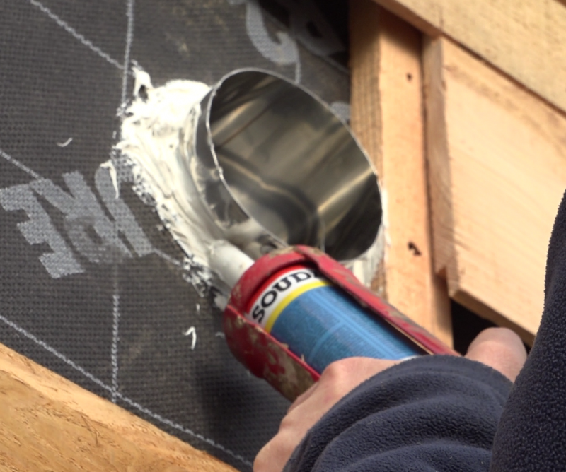
- Placer le tube dans la paroi, au niveau de la sortie d'air du capteur, le clapet vers l'habitat.
Étape 15 - Installation
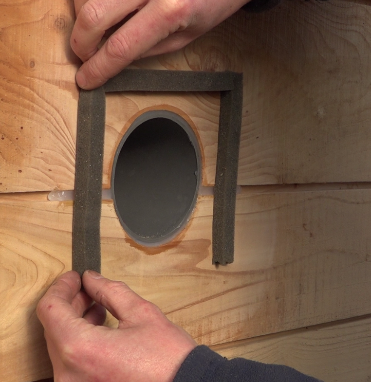
- Coller un joint compribande autour des trous entrée et sortie sur l'habitat.
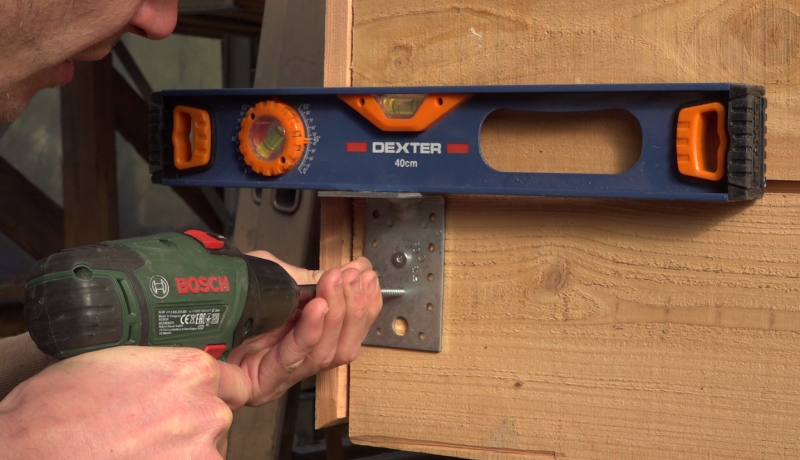
- Positionner des équerres de supports du capteurs sur le mur, en bas et en haut, puis visser le capteur bien accolé à la paroi afin que les joints compribande soient sollicités.
Étape 16 - Utilisation
Hiver:
- Laissez la trappe été bien fermée.
- Le soleil rasant d'hiver rayonne sur les ardoises qui vont chauffer l'enceinte du capteur.
- Par effet de "thermosyphon", l'air chaud va naturellement monter, créant ainsi un tirage aspirant l'air de l'habitat par le bas du capteur.
- La circulation ne sera permise par le clapet que quand la température dans le capteur dépassera les 25°C.
Eté:
- Ouvrir la trappe été
- Le soleil rayonne sur les ardoises qui vont chauffer le système.
- L'air va naturellement monter et s'échapper dehors par la trappe été.
- Une aspiration par le trous bas du capteur va permettre d’évacuer l'air de l'habitat créant ainsi une ventilation estivale naturelle.
Notes et références
- Guy Isabel, Les capteurs solaires à air, édition Eyrolles.
- Tutoriel réalisé par Camille Duband et Pierre-Alain Lévêque dans le cadre du Low-tech Tour, Février 2018.
- Merci à Jean Daniel Blanchet pour l'expérimentation sur l'une de ces tiny houses, penty cosy à Langolen, Bretagne.
- Merci à Benjamin et Mickaël pour leur aide.
- Corps noir, wikipedia.
Yes

 Français
 English
 Deutsch
 Español
 Italiano
 Português