(Page créée avec « '''<u>First technique using a strainer (image 1):</u>''' ») |
(Mise à jour pour être en accord avec la nouvelle version de la source de la page) |
||
| (44 révisions intermédiaires par 2 utilisateurs non affichées) | |||
| Ligne 1 : | Ligne 1 : | ||
{{Tuto Details | {{Tuto Details | ||
| − | |Main_Picture= | + | |Main_Picture=B_lier_hydraulique_P2251150.JPG |
|Licences=Attribution (CC BY) | |Licences=Attribution (CC BY) | ||
| − | |Description=The purpose of this tutorial is to facilitate the understanding, design, manufacture and installation of a water elevation system called "Ram pump". This technology was documented during a stopover of the Sea Nomad in the Philippines, on the island of Negros. The NGO "Alternative Indigenous Development Foundation (AIFDI)", based in the city of Bacolod since 1991, helps more than 160 rural communities meet their water needs by installing hydraulic rams throughout the archipelago. | + | |Description=<div class="mw-translate-fuzzy"> |
| + | The purpose of this tutorial is to facilitate the understanding, design, manufacture and installation of a water elevation system called "Ram pump". This technology was documented during a stopover of the Sea Nomad in the Philippines, on the island of Negros. The NGO "Alternative Indigenous Development Foundation (AIFDI)", based in the city of Bacolod since 1991, helps more than 160 rural communities meet their water needs by installing hydraulic rams throughout the archipelago. | ||
The ram pump presented in this tutorial is a different version from the one used by the AIFDI because it is more accessible. | The ram pump presented in this tutorial is a different version from the one used by the AIFDI because it is more accessible. | ||
| + | </div> | ||
|Area=Water | |Area=Water | ||
|Type=Tutorial | |Type=Tutorial | ||
| Ligne 11 : | Ligne 13 : | ||
|Cost=100 | |Cost=100 | ||
|Currency=EUR (€) | |Currency=EUR (€) | ||
| − | |Tags= | + | |Tags=récupération, upcycling, eau, tuyauterie, bélier, hydraulique, pump, ram pump, pompe |
|SourceLanguage=fr | |SourceLanguage=fr | ||
|Language=en | |Language=en | ||
| Ligne 17 : | Ligne 19 : | ||
}} | }} | ||
{{Introduction | {{Introduction | ||
| − | |Introduction= | + | |Introduction=====Historique du bélier hydraulique==== |
The hydraulic ram system was invented in 1797 by Joseph-Michel Montgolfier, the man who built the first hot air balloon in 1782 with his brother, Jacques-Étienne. He was immediately criticized by his contemporaries who associated him with the theories of perpetual movement, which were considered heresies at the time. | The hydraulic ram system was invented in 1797 by Joseph-Michel Montgolfier, the man who built the first hot air balloon in 1782 with his brother, Jacques-Étienne. He was immediately criticized by his contemporaries who associated him with the theories of perpetual movement, which were considered heresies at the time. | ||
| Ligne 26 : | Ligne 28 : | ||
<br /> | <br /> | ||
| − | == | + | ====A quoi sert un bélier hydraulique?==== |
The hydraulic ram pump is a water elevation system whose operation depends solely on the driving force of the water, without any other external intervention. In concrete terms, this makes possible to pump water from a source (river, lake, stream) and use it higher to irrigate crops, water livestock or for any other domestic use. | The hydraulic ram pump is a water elevation system whose operation depends solely on the driving force of the water, without any other external intervention. In concrete terms, this makes possible to pump water from a source (river, lake, stream) and use it higher to irrigate crops, water livestock or for any other domestic use. | ||
| Ligne 40 : | Ligne 42 : | ||
{{TutoVideo | {{TutoVideo | ||
|VideoType=Youtube | |VideoType=Youtube | ||
| − | |VideoURLYoutube=https://www.youtube.com/watch?v= | + | |VideoURLYoutube=https://www.youtube.com/watch?v=W9kEUdwIfVk |
}} | }} | ||
{{Materials | {{Materials | ||
|Step_Picture_00=Pompe-belier-hydrolique_image6.jpg | |Step_Picture_00=Pompe-belier-hydrolique_image6.jpg | ||
| + | |Step_Picture_01=B_lier_hydraulique_P22309200.JPG | ||
| + | |Step_Picture_02=B_lier_hydraulique_P2230925.JPG | ||
|Material='''Do not use plastic material for the ram, whether valves or flaps, as they will wear out very quickly during operation..''' | |Material='''Do not use plastic material for the ram, whether valves or flaps, as they will wear out very quickly during operation..''' | ||
| Ligne 50 : | Ligne 54 : | ||
'''To buy:''' | '''To buy:''' | ||
| + | <div class="mw-translate-fuzzy"> | ||
-vanne of 26/34mm | -vanne of 26/34mm | ||
| + | </div> | ||
| + | <div class="mw-translate-fuzzy"> | ||
-1 elbow of 26/34 | -1 elbow of 26/34 | ||
| + | </div> | ||
| + | <div class="mw-translate-fuzzy"> | ||
-3 male plumbing nipples in 26/34 | -3 male plumbing nipples in 26/34 | ||
| + | </div> | ||
| + | <div class="mw-translate-fuzzy"> | ||
-1 Tee of 26/34 | -1 Tee of 26/34 | ||
| + | </div> | ||
| + | <div class="mw-translate-fuzzy"> | ||
-1 strainer in 26/34 or a plastic check valve inside (see step 5) | -1 strainer in 26/34 or a plastic check valve inside (see step 5) | ||
| + | </div> | ||
| + | <div class="mw-translate-fuzzy"> | ||
-1 check valve in 26/34 with stainless steel/brass interior | -1 check valve in 26/34 with stainless steel/brass interior | ||
| + | </div> | ||
| + | <div class="mw-translate-fuzzy"> | ||
-2 valves in 20/27 or 1 valve with drain valve | -2 valves in 20/27 or 1 valve with drain valve | ||
| + | </div> | ||
| + | <div class="mw-translate-fuzzy"> | ||
-1 cross of 20/27 | -1 cross of 20/27 | ||
| + | </div> | ||
| + | <div class="mw-translate-fuzzy"> | ||
-1 reduction from 26/34 to 20/27 | -1 reduction from 26/34 to 20/27 | ||
| + | </div> | ||
| + | <div class="mw-translate-fuzzy"> | ||
-1 or 2 teflon rollers for sealing the entire assembly | -1 or 2 teflon rollers for sealing the entire assembly | ||
| + | </div> | ||
| + | <div class="mw-translate-fuzzy"> | ||
-Thread lock for fixing the threaded rod | -Thread lock for fixing the threaded rod | ||
| + | </div> | ||
| + | <div class="mw-translate-fuzzy"> | ||
-4 rods with wing nuts | -4 rods with wing nuts | ||
| + | </div> | ||
| + | <div class="mw-translate-fuzzy"> | ||
- a dozen washers with an internal diameter of 6mm | - a dozen washers with an internal diameter of 6mm | ||
| + | </div> | ||
| + | <div class="mw-translate-fuzzy"> | ||
-2 nuts for M5 threaded rod | -2 nuts for M5 threaded rod | ||
| + | </div> | ||
'''To be recovered:''' | '''To be recovered:''' | ||
| + | <div class="mw-translate-fuzzy"> | ||
-1 extinguisher of 7 or 9 litres | -1 extinguisher of 7 or 9 litres | ||
| + | </div> | ||
| + | <div class="mw-translate-fuzzy"> | ||
-1 inner tube or other rubber to make a seal | -1 inner tube or other rubber to make a seal | ||
| + | </div> | ||
| + | <div class="mw-translate-fuzzy"> | ||
- Nails | - Nails | ||
| + | </div> | ||
| + | <div class="mw-translate-fuzzy"> | ||
- 1 wooden board | - 1 wooden board | ||
| + | </div> | ||
| + | <div class="mw-translate-fuzzy"> | ||
-flat iron 20 or 30 mm wide, about 60 cm | -flat iron 20 or 30 mm wide, about 60 cm | ||
| + | </div> | ||
| + | <div class="mw-translate-fuzzy"> | ||
-a torch (according to step 5) | -a torch (according to step 5) | ||
| − | |Tools=- a plier | + | </div> |
| + | |Tools=<div class="mw-translate-fuzzy"> | ||
| + | - a plier | ||
| + | </div> | ||
| + | <div class="mw-translate-fuzzy"> | ||
- a claw to open the strainer | - a claw to open the strainer | ||
| + | </div> | ||
| + | <div class="mw-translate-fuzzy"> | ||
- Scissors | - Scissors | ||
| + | </div> | ||
| + | <div class="mw-translate-fuzzy"> | ||
- Hammer | - Hammer | ||
| + | </div> | ||
| + | <div class="mw-translate-fuzzy"> | ||
- -a drill bit (here 6, 7mm) | - -a drill bit (here 6, 7mm) | ||
| + | </div> | ||
| + | <div class="mw-translate-fuzzy"> | ||
- a tap ( here M5) | - a tap ( here M5) | ||
| + | </div> | ||
}} | }} | ||
{{Tuto Step | {{Tuto Step | ||
| Ligne 117 : | Ligne 173 : | ||
[https://www.youtube.com/watch?v=hsCaMW7L2yI Video explanations] | [https://www.youtube.com/watch?v=hsCaMW7L2yI Video explanations] | ||
|Step_Picture_00=Pompe-belier-hydrolique_Capture.PNG | |Step_Picture_00=Pompe-belier-hydrolique_Capture.PNG | ||
| − | |||
}} | }} | ||
{{Tuto Step | {{Tuto Step | ||
| Ligne 218 : | Ligne 273 : | ||
|Step_Picture_00=Pompe-belier-hydrolique_xUzrUg04GUZPxYPOMmM2yPs4-2w.jpg | |Step_Picture_00=Pompe-belier-hydrolique_xUzrUg04GUZPxYPOMmM2yPs4-2w.jpg | ||
|Step_Picture_01=Pompe-belier-hydrolique_1aQH6Ymk9cC77591OqMGlCA0cWI.jpg | |Step_Picture_01=Pompe-belier-hydrolique_1aQH6Ymk9cC77591OqMGlCA0cWI.jpg | ||
| + | |Step_Picture_02=B_lier_hydraulique_P2251120.JPG | ||
}} | }} | ||
{{Tuto Step | {{Tuto Step | ||
|Step_Title=Air chamber | |Step_Title=Air chamber | ||
| − | |Step_Content=To disassemble the extinguisher, you should unscrew the mouthpiece with a wrench and take out the CO2 cartridge it contains. | + | |Step_Content=<div class="mw-translate-fuzzy"> |
| + | To disassemble the extinguisher, you should unscrew the mouthpiece with a wrench and take out the CO2 cartridge it contains. | ||
| + | </div> | ||
| + | <div class="mw-translate-fuzzy"> | ||
Then, take out the plastic pipe and the lance. | Then, take out the plastic pipe and the lance. | ||
| + | </div> | ||
The outer part is normalised 20x27 and will be screwed to the pump. | The outer part is normalised 20x27 and will be screwed to the pump. | ||
| Ligne 231 : | Ligne 291 : | ||
The lance hole should be stuck with something that resists pressure ! If you don' find a lid, you can weld a round metallic part on it. | The lance hole should be stuck with something that resists pressure ! If you don' find a lid, you can weld a round metallic part on it. | ||
| − | + | - | |
{{Idea|If you don't have an extinguisher, it is possible to build an air chamber with a tube stuck at both ends and a PVC fitting. The linkage between the fitting and a standard pipe end is done thanks to a threaded reduction, more difficul to find on the market (see photo) }}<br /> | {{Idea|If you don't have an extinguisher, it is possible to build an air chamber with a tube stuck at both ends and a PVC fitting. The linkage between the fitting and a standard pipe end is done thanks to a threaded reduction, more difficul to find on the market (see photo) }}<br /> | ||
| − | |Step_Picture_00= | + | |Step_Picture_00=B_lier_hydraulique_P2240938.JPG |
| − | |Step_Picture_01=Pompe-belier-hydrolique_zoVIu2n-CRXjlY6SD21nyRATmCU.jpg | + | |Step_Picture_01=B_lier_hydraulique_P2240942.JPG |
| + | |Step_Picture_02=Pompe-belier-hydrolique_zoVIu2n-CRXjlY6SD21nyRATmCU.jpg | ||
}} | }} | ||
{{Tuto Step | {{Tuto Step | ||
| Ligne 243 : | Ligne 304 : | ||
'''<u>First technique using a strainer (image 1):</u>''' | '''<u>First technique using a strainer (image 1):</u>''' | ||
| − | '' | + | ''This version is the sturdiest, but will be a bit harder to build'' |
| − | + | Firstly, disassemble the strainer using a claw clamp. | |
| − | + | One the valve is recovered, drill a hole is the center with a 4mm drill. You might ask a turner in his workshop. | |
| − | + | Tap at 5mm. | |
| − | + | Drill a 6 or 7 mm hole at the top center of the strainer. | |
| − | + | Insert the rod in the 5mm hole, with a bit of thread lock. | |
| − | [https://www.youtube.com/watch?v=HZNX5r4G-cs] | + | [https://www.youtube.com/watch?v=HZNX5r4G-cs]Watching this video will help you to understand the strain disassembly : https://www.youtube.com/watch?v=HZNX5r4G-cs |
| − | '''<u> | + | <div class="mw-translate-fuzzy"> |
| + | '''<u>Second technique using a non-return valve(image 3):</u>''' | ||
| + | </div> | ||
| − | '' | + | ''This technique is less sturdy but more accessible because this kind of valve in plastic can be found in most shops.'' |
| − | + | To open the anti-return valve: | |
| − | - | + | <div class="mw-translate-fuzzy"> |
| + | -place male fittings on each side on the valve to avoid damaging it during the operation | ||
| + | </div> | ||
| − | - | + | -Distinguish a very thin line that separates two parts of the valve |
| − | - | + | -Heat at the level of this line using a blowtorch, in order to melt the glue on the inside (be careful not to heat to much). |
| − | - | + | -Unscrew the valve (using a claw clamp and a vice for example) |
| − | + | Then, remove the plastic flap inside and replace it by a washer, nuts and a threaded rod. (as shown on the 4th image). | |
| − | <br />{{Warning| | + | <br />{{Warning|For both techniques, it is really important to put the threaded rod at the center of the system, otherwise it would get stuck and block the whole system.}}<br /> |
| − | |Step_Picture_00= | + | |Step_Picture_00=B_lier_hydraulique_P2241054.JPG |
|Step_Picture_01=Pompe-belier-hydrolique_image41.jpg | |Step_Picture_01=Pompe-belier-hydrolique_image41.jpg | ||
| − | |Step_Picture_02=Pompe-belier-hydrolique_52199-28971-medium.jpg | + | |Step_Picture_02=B_lier_hydraulique_P2241048.JPG |
| − | | | + | |Step_Picture_03=Pompe-belier-hydrolique_52199-28971-medium.jpg |
| − | | | + | |Step_Picture_04=Pompe-belier-hydrolique_Clapet_1.jpg |
| − | + | |Step_Picture_05=Pompe-belier-hydrolique_one.JPG | |
}} | }} | ||
{{Tuto Step | {{Tuto Step | ||
| − | |Step_Title= | + | |Step_Title=Assembly |
| − | |Step_Content= | + | |Step_Content=Before assembling the system, cover the threads in teflon or any other way of ensuring its sealing. |
| − | + | [https://www.youtube.com/watch?v=EtYyMO6be0w This video] explains the teflon coating. | |
| − | + | Then assembly the pump according to this scheme. | |
| − | {{Warning| | + | {{Warning|It is really important to seal the pump properly because any leak would cause important damages to the final performance!}}<br /> |
| − | |Step_Picture_00= | + | |Step_Picture_00=B_lier_hydraulique_P2240987.JPG |
| + | |Step_Picture_01=B_lier_hydraulique_P2230925.JPG | ||
| + | |Step_Picture_02=B_lier_hydraulique_P2241013.JPG | ||
}} | }} | ||
{{Tuto Step | {{Tuto Step | ||
|Step_Title=Support | |Step_Title=Support | ||
| − | |Step_Content= | + | |Step_Content=To choose a support, you should take into account the system size, in particular the air chamber size, because it may unbalance the whole. The base can be made of wood or metal but for pumps that will be used for a long time, the ideal is to lay a concrete slab. |
| − | + | Cut irons depending on the required length. | |
| − | + | Build 2 or 3 pieces in an arc shape using the nails method (the arc diameter should be of the fittings size). | |
| − | + | Pierce the arc pieces and the base at the good spots in order to obtain a good clamping but not excessive (it would damage the pipes). | |
| − | + | Fix the the pump on the base with the arc pieces using threaded rods and wing nuts. | |
| − | {{Idea| | + | {{Idea|To prevent this air chamber from oscillating, which would damage the system, it is possible to add a stent attached to the base or planted in the ground.}}<br /> |
|Step_Picture_00=Pompe-belier-hydrolique_support.png | |Step_Picture_00=Pompe-belier-hydrolique_support.png | ||
| + | |Step_Picture_01=B_lier_hydraulique_P2251107.JPG | ||
| + | |Step_Picture_02=B_lier_hydraulique_P2251112.JPG | ||
}} | }} | ||
{{Tuto Step | {{Tuto Step | ||
| − | |Step_Title= | + | |Step_Title=Activation |
| − | |Step_Content= | + | |Step_Content=Firstly, place the ram pump in a flat and even spot, using a bubble level if necessary. Install then the driving pipe and the delivery pipe and plug them (don't forget the teflon for sealing). |
| − | + | At the beggining the pump is empty from water and all valves are closed. Open a little the delivery tap (leading to the tank) and then open fully the water inlet valve (coming from the drive pipe). Water will then push the primary valve and activate the system. | |
| − | + | If doesn't work properly, you may activate it manually several times in order to have enough conter pressure in the delivery pipe. If the washers are to heavy, or if the valves' trajectory is not adapted, if may still not work properly. This model allows you to make adjustements by moving the first nut and the number of washers. This settings will also impact the quantity of water in the delivery pipe, compared to the waste water. | |
| − | {{Pin| | + | {{Pin|The more washers there is, the strongest the water hammer will be, but the frequency will be lower. It is necessary to find the balance between the frequency and the strength of the water hammer.}} |
| − | + | You will have to drain regularly the pump. Indeed, there must always be air under pressure in the chamber (pressure is given bu the water push). This air will empty progressively. To fix this, you will have to close both taps (drive and delivery taps), open the drain tap and reactivate the system as shown before. | |
| − | [https://www.youtube.com/watch?v=NoQrU15cRFc | + | [https://www.youtube.com/watch?v=NoQrU15cRFc See this video for explanations] |
| − | |Step_Picture_00= | + | |Step_Picture_00=B_lier_hydraulique_P2251150.JPG |
| + | |Step_Picture_01=B_lier_hydraulique_P3031416.JPG | ||
| + | }} | ||
| + | {{Tuto Step | ||
| + | |Step_Title=Donnez-nous votre avis | ||
| + | |Step_Content='''Vous avez une minute ? Que vous souhaitiez ou non réaliser cette low-tech, votre réponse à [https://framaforms.org/votre-avis-sur-ce-tutoriel-du-low-tech-lab-1589450161 ce formulaire] nous aiderait à améliorer nos tutos. Merci d'avance pour votre aide !''' | ||
| + | |||
| + | Comme tout le travail du Low-tech Lab, '''ce tutoriel est participatif''', n'hésitez pas à ajouter les modifications qui vous semblent importantes, et à partager vos réalisations en commentaires. | ||
}} | }} | ||
{{Notes | {{Notes | ||
| − | |Notes=*[https://www.permatheque.fr/2015/03/03/pompe-belier-hydrolique/ Permatheque] | + | |Notes=<div class="mw-translate-fuzzy"> |
| + | *[https://www.permatheque.fr/2015/03/03/pompe-belier-hydrolique/ Permatheque] | ||
| + | *[https://www.permatheque.fr/PDF/Realisation%20d'un%20Belier%20Hydrolique.pdf PDF] On water upwelling, leaks ... | ||
| + | *http://www.belier-inox.fr/fabriquez-votre-belier-p867652 | ||
| + | *http://www.pearltrees.com/apfeltheo/construction/id12619255#item125024933 | ||
| + | *http://www.regispetit.fr/bel_pra.htm#pra7 | ||
| + | *http://www.cluber.inter-systeme.ca/belier.html | ||
| + | *https://sites.google.com/site/fabricationdunepompeabelier/ | ||
| + | *https://www.humanosphere.info/2014/07/comment-construire-une-pompe-a-eau-qui-fonctionne-sans-electricite/ | ||
| + | </div> | ||
| + | |||
| + | Merci à Alizée et Yoann du projet [http://cheminsdefaire.fr/ Chemins de Faire] pour les photos et les retours d'expériences. | ||
| + | |||
| + | *[https://www.permatheque.fr/2015/03/03/pompe-belier-hydrolique/ Permatheque] | ||
*[https://www.permatheque.fr/PDF/Realisation%20d'un%20Belier%20Hydrolique.pdf PDF] sur la remontée d'eau, les conduites, les débits... | *[https://www.permatheque.fr/PDF/Realisation%20d'un%20Belier%20Hydrolique.pdf PDF] sur la remontée d'eau, les conduites, les débits... | ||
*http://www.belier-inox.fr/fabriquez-votre-belier-p867652 | *http://www.belier-inox.fr/fabriquez-votre-belier-p867652 | ||
Version du 8 mars 2021 à 13:18

Difficulté
Facile
Durée
2 jour(s)
Coût
100 EUR (€)
Description
The purpose of this tutorial is to facilitate the understanding, design, manufacture and installation of a water elevation system called "Ram pump". This technology was documented during a stopover of the Sea Nomad in the Philippines, on the island of Negros. The NGO "Alternative Indigenous Development Foundation (AIFDI)", based in the city of Bacolod since 1991, helps more than 160 rural communities meet their water needs by installing hydraulic rams throughout the archipelago. The ram pump presented in this tutorial is a different version from the one used by the AIFDI because it is more accessible.
The purpose of this tutorial is to facilitate the understanding, design, manufacture and installation of a water elevation system called "Ram pump". This technology was documented during a stopover of the Sea Nomad in the Philippines, on the island of Negros. The NGO "Alternative Indigenous Development Foundation (AIFDI)", based in the city of Bacolod since 1991, helps more than 160 rural communities meet their water needs by installing hydraulic rams throughout the archipelago. The ram pump presented in this tutorial is a different version from the one used by the AIFDI because it is more accessible.
Sommaire
Sommaire
- 1 Description
- 2 Sommaire
- 3 Introduction
- 4 Video d'introduction
- 5 Étape 1 - How does a ram pump work?
- 6 Étape 2 - Evaluate a site and size the ram pump
- 7 Étape 3 - Choose your type of installation
- 8 Étape 4 - Air chamber
- 9 Étape 5 - Primary valve (or impact valve)
- 10 Étape 6 - Assembly
- 11 Étape 7 - Support
- 12 Étape 8 - Activation
- 13 Étape 9 - Donnez-nous votre avis
- 14 Notes et références
- 15 Commentaires
Introduction
Historique du bélier hydraulique
The hydraulic ram system was invented in 1797 by Joseph-Michel Montgolfier, the man who built the first hot air balloon in 1782 with his brother, Jacques-Étienne. He was immediately criticized by his contemporaries who associated him with the theories of perpetual movement, which were considered heresies at the time.
It was not until 1857 that a patent was filed by Ernest Sylvain Bollée, which improved and made Montgolfier's invention a reality.
Since then, it has been widely used in the French and European countryside, and is now established in America and Africa in regions where fuel supplies are difficult or expensive.
A quoi sert un bélier hydraulique?
The hydraulic ram pump is a water elevation system whose operation depends solely on the driving force of the water, without any other external intervention. In concrete terms, this makes possible to pump water from a source (river, lake, stream) and use it higher to irrigate crops, water livestock or for any other domestic use.
The ram pump has several advantages:
- It is relatively inexpensive
- It operates fully automatically, without electricity, over a long period of time, some rams have been operating for several decades
- It requires no lubrication, no maintenance other than cleanliness care
- Repairs are infrequent, only necessary due to the inevitable wear and tear of moving parts
- It can be adapted to almost any size to suit the desired flow rates and heights
Youtube

Erreur lors de la création de la miniature : convert: unable to extend cache `/var/www/dokitfarm/sites/Low_tech_Lab/images/0/02/B_lier_hydraulique_P22309200.JPG': File too large @ error/cache.c/OpenPixelCache/4006. convert: no images defined `/tmp/transform_67500aea0e82.jpg' @ error/convert.c/ConvertImageCommand/3258. Error code: 1

- Erreur lors de la création de la miniature : convert: unable to extend cache `/var/www/dokitfarm/sites/Low_tech_Lab/images/0/02/B_lier_hydraulique_P22309200.JPG': File too large @ error/cache.c/OpenPixelCache/4006. convert: no images defined `/tmp/transform_8f17964ed6a5.jpg' @ error/convert.c/ConvertImageCommand/3258. Error code: 1
Matériaux
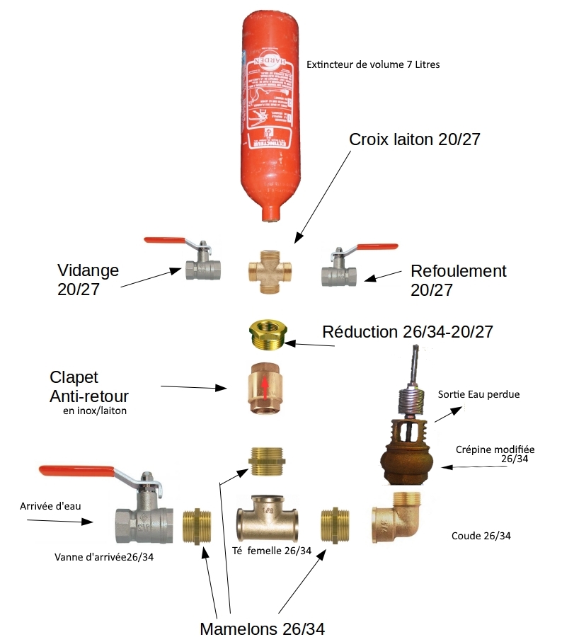
Do not use plastic material for the ram, whether valves or flaps, as they will wear out very quickly during operation..
To buy:
-vanne of 26/34mm
-1 elbow of 26/34
-3 male plumbing nipples in 26/34
-1 Tee of 26/34
-1 strainer in 26/34 or a plastic check valve inside (see step 5)
-1 check valve in 26/34 with stainless steel/brass interior
-2 valves in 20/27 or 1 valve with drain valve
-1 cross of 20/27
-1 reduction from 26/34 to 20/27
-1 or 2 teflon rollers for sealing the entire assembly
-Thread lock for fixing the threaded rod
-4 rods with wing nuts
- a dozen washers with an internal diameter of 6mm
-2 nuts for M5 threaded rod
To be recovered:
-1 extinguisher of 7 or 9 litres
-1 inner tube or other rubber to make a seal
- Nails
- 1 wooden board
-flat iron 20 or 30 mm wide, about 60 cm
-a torch (according to step 5)
Outils
- a plier
- a claw to open the strainer
- Scissors
- Hammer
- -a drill bit (here 6, 7mm)
- a tap ( here M5)
Étape 1 - How does a ram pump work?
- When priming, water flowing into the inlet line flows into the weir through the primary valve.
- The acceleration of the water causes the primary valve to close suddenly.
- The water column is suddenly braked and generates an overpressure in the pump casing (water hammer), which opens the internal valve.
- Under the effect of this overpressure, water flows into the balloon (and the discharge duct), compressing the air volume until the pressures are balanced.
- The pressure reversal closes the internal valve.
- The water trapped under pressure in the balloon empties into the discharge line until the pressures are balanced (determined by the height of the pipe).
- The closing of the internal valve has caused the pressure to drop, so the primary valve opens again. A new cycle begins....
Without accident, this process is perpetually renewed as long as it is supplied with water.

Étape 2 - Evaluate a site and size the ram pump
First of all, it is necessary to find surface water that continuously flows on a sufficiently steep slope (about 10% minimum). If it's a dam or lake, make sure that there are positions below.
To evaluate a site, 4 parameters have to be estimated (as shown on the scheme) :
- q water flow
- H lift height
- L driving line lenght
- h fall height
Concerning the water flow, it it not necessary to be really precise, an average value would be enough to size the system. Several techniques are available, depending on your material and time : see Water flow estimation"
The lift height corresponds to the height difference between the pump height and the water reservoir. Concretely you should decide where you want the water to arrive, and measure the height difference between this point and the water source (in average). This measure will be precised later in the process. Slope measuring can be done with this website https://www.geoportail.gouv.fr/carte : Place GPS coordinates on the map, and use the function "asymetric profile". This correspond to a curve showing the elevation depending on the distance (in m).
The driving line lenght and the fall height are directly related to the river or lake slope. In this case as well, it would be interesting to establish an asymetric profile in order to take distances and elevation gradients into account.
Once the parameters of the site are identified, we will size the pump in order to retrieve the needed flow and a minimal installation coast (the smaller the pump is, the cheaper it will be).
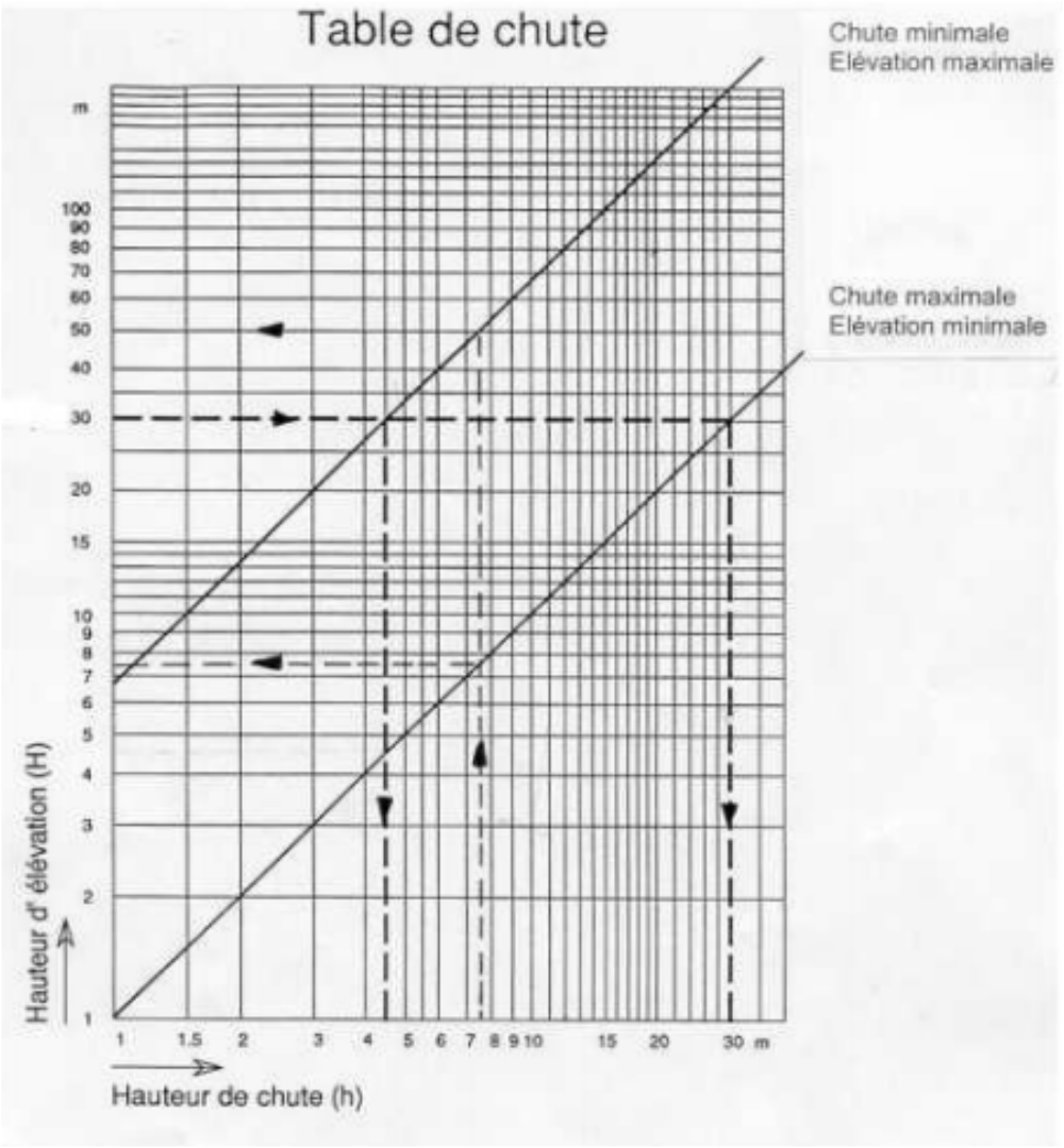
Determine L, H and h:
General Formula: q=((h*Q)/(h + H))0.70
Where 0.70 is the pump efficiency and Q the arrival flow.
Concretely, you will need:
- H/10<h<H/2
- 3H <L<15H
You can also use a fall diagram as shown on the picture to determine H and h.
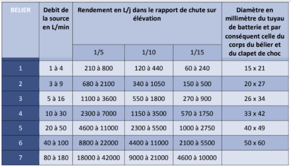
Sizing of the pump:
To size the pump itself, you have to chose the needed arrival flow. One of the easiest ways to do that is to use the provided table, that gives the final pipe size according to the source flow, the elevation ratio h/H and the final flow.
Using the table, you can proceed as follows:
- Choose the final flow, corresponding to you water needs
- Find the corresponding number in the table according to the elevation ratios of your site
- Do not hesitate to oversize the system in case of doubt
- Verify that you water flow is higher than indicated in the table
- On the same table line, you can read the relevant pump sizing for you situation
You obtain the battery pipe (or driving line) diameter D, which is the same for all other components of the pump.
For example: 26x34 to an internal diamter of 26mm and an external diameter of 34mm| Millimeters (mm) | Inches |
| 15x21 | 1/2 |
| 20x27 | 3/4 |
| 26x34 | 1 |
| 33x42 | 1 1/4 |
| 40x49 | 1 1/2 |
| 50x60 | 2 |
All pump components will therefore be of the same dimension, except for the outlet pipe (or delivery pipe) whose diameter D' will be half of the driving line D. D'=D/2

Étape 3 - Choose your type of installation
When building a ram pump, 2 different configurations exist that will play a role on the pump efficiency. They concern positions of the primary valve, the internal valve and the air chamber.
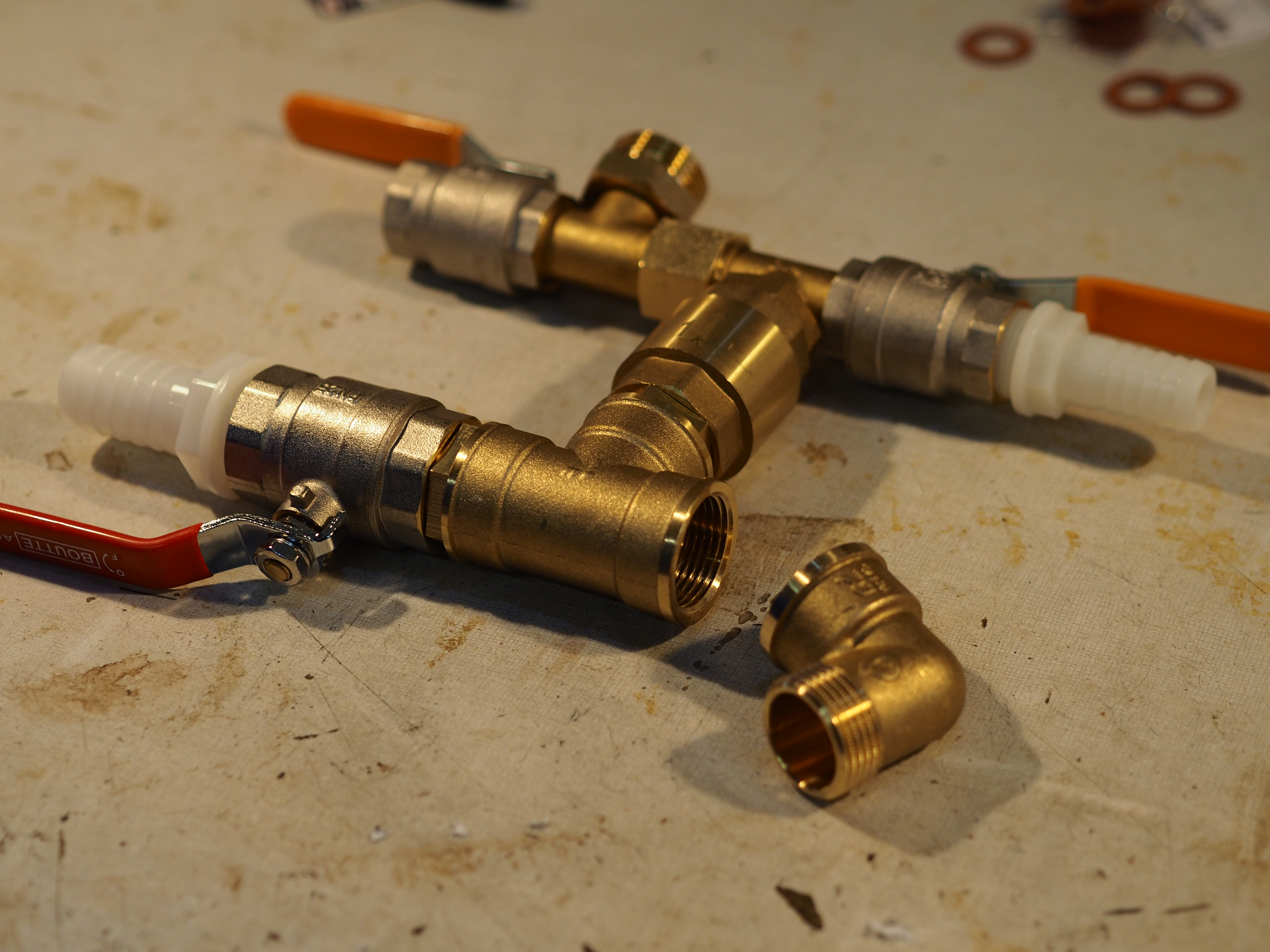
Repartition assembly (image 1):
In this case, the primary valve is before the air chamber. This position can make the pump look rather flat, as shown in the first picture of this page. Some sources state that this system can reach 20% higher performance than the other, but we have not been able to prove it yet.
In butting assembly (image 2):
We will describe this system in the tutorial, as it is more widely used. The pump will look more vertical.


Étape 4 - Air chamber
To disassemble the extinguisher, you should unscrew the mouthpiece with a wrench and take out the CO2 cartridge it contains.
Then, take out the plastic pipe and the lance.
The outer part is normalised 20x27 and will be screwed to the pump.
To obtain a functional air chamber, you should also empty it from the powder and clean the inside of the extinguisher.
The lance hole should be stuck with something that resists pressure ! If you don' find a lid, you can weld a round metallic part on it.
-


Étape 5 - Primary valve (or impact valve)
First technique using a strainer (image 1):
This version is the sturdiest, but will be a bit harder to build
Firstly, disassemble the strainer using a claw clamp.
One the valve is recovered, drill a hole is the center with a 4mm drill. You might ask a turner in his workshop.
Tap at 5mm.
Drill a 6 or 7 mm hole at the top center of the strainer.
Insert the rod in the 5mm hole, with a bit of thread lock.
[1]Watching this video will help you to understand the strain disassembly : https://www.youtube.com/watch?v=HZNX5r4G-cs
Second technique using a non-return valve(image 3):
This technique is less sturdy but more accessible because this kind of valve in plastic can be found in most shops.
To open the anti-return valve:
-place male fittings on each side on the valve to avoid damaging it during the operation
-Distinguish a very thin line that separates two parts of the valve
-Heat at the level of this line using a blowtorch, in order to melt the glue on the inside (be careful not to heat to much).
-Unscrew the valve (using a claw clamp and a vice for example)
Then, remove the plastic flap inside and replace it by a washer, nuts and a threaded rod. (as shown on the 4th image).


Étape 6 - Assembly
Before assembling the system, cover the threads in teflon or any other way of ensuring its sealing.
This video explains the teflon coating.
Then assembly the pump according to this scheme.


Étape 7 - Support
To choose a support, you should take into account the system size, in particular the air chamber size, because it may unbalance the whole. The base can be made of wood or metal but for pumps that will be used for a long time, the ideal is to lay a concrete slab.
Cut irons depending on the required length.
Build 2 or 3 pieces in an arc shape using the nails method (the arc diameter should be of the fittings size).
Pierce the arc pieces and the base at the good spots in order to obtain a good clamping but not excessive (it would damage the pipes).
Fix the the pump on the base with the arc pieces using threaded rods and wing nuts.


Étape 8 - Activation
Firstly, place the ram pump in a flat and even spot, using a bubble level if necessary. Install then the driving pipe and the delivery pipe and plug them (don't forget the teflon for sealing).
At the beggining the pump is empty from water and all valves are closed. Open a little the delivery tap (leading to the tank) and then open fully the water inlet valve (coming from the drive pipe). Water will then push the primary valve and activate the system.
If doesn't work properly, you may activate it manually several times in order to have enough conter pressure in the delivery pipe. If the washers are to heavy, or if the valves' trajectory is not adapted, if may still not work properly. This model allows you to make adjustements by moving the first nut and the number of washers. This settings will also impact the quantity of water in the delivery pipe, compared to the waste water.
You will have to drain regularly the pump. Indeed, there must always be air under pressure in the chamber (pressure is given bu the water push). This air will empty progressively. To fix this, you will have to close both taps (drive and delivery taps), open the drain tap and reactivate the system as shown before.


Étape 9 - Donnez-nous votre avis
Vous avez une minute ? Que vous souhaitiez ou non réaliser cette low-tech, votre réponse à ce formulaire nous aiderait à améliorer nos tutos. Merci d'avance pour votre aide !
Comme tout le travail du Low-tech Lab, ce tutoriel est participatif, n'hésitez pas à ajouter les modifications qui vous semblent importantes, et à partager vos réalisations en commentaires.
Notes et références
- Permatheque
- PDF On water upwelling, leaks ...
- http://www.belier-inox.fr/fabriquez-votre-belier-p867652
- http://www.pearltrees.com/apfeltheo/construction/id12619255#item125024933
- http://www.regispetit.fr/bel_pra.htm#pra7
- http://www.cluber.inter-systeme.ca/belier.html
- https://sites.google.com/site/fabricationdunepompeabelier/
- https://www.humanosphere.info/2014/07/comment-construire-une-pompe-a-eau-qui-fonctionne-sans-electricite/
Merci à Alizée et Yoann du projet Chemins de Faire pour les photos et les retours d'expériences.
- Permatheque
- PDF sur la remontée d'eau, les conduites, les débits...
- http://www.belier-inox.fr/fabriquez-votre-belier-p867652
- http://www.pearltrees.com/apfeltheo/construction/id12619255#item125024933
- http://www.regispetit.fr/bel_pra.htm#pra7
- http://www.cluber.inter-systeme.ca/belier.html
- https://sites.google.com/site/fabricationdunepompeabelier/
- https://www.humanosphere.info/2014/07/comment-construire-une-pompe-a-eau-qui-fonctionne-sans-electricite/
Published
 Français
 English
 Deutsch
 Español
 Italiano
 Português